EP2674264A2 - Robot doté d'un changeur d'outil - Google Patents
Robot doté d'un changeur d'outil Download PDFInfo
- Publication number
- EP2674264A2 EP2674264A2 EP13172056.7A EP13172056A EP2674264A2 EP 2674264 A2 EP2674264 A2 EP 2674264A2 EP 13172056 A EP13172056 A EP 13172056A EP 2674264 A2 EP2674264 A2 EP 2674264A2
- Authority
- EP
- European Patent Office
- Prior art keywords
- robot according
- robot
- tool
- tools
- tilting
- Prior art date
- Legal status (The legal status is an assumption and is not a legal conclusion. Google has not performed a legal analysis and makes no representation as to the accuracy of the status listed.)
- Withdrawn
Links
- 230000005540 biological transmission Effects 0.000 claims abstract description 4
- 239000007787 solid Substances 0.000 claims description 23
- 239000007788 liquid Substances 0.000 claims description 15
- 230000008878 coupling Effects 0.000 claims description 8
- 238000010168 coupling process Methods 0.000 claims description 8
- 238000005859 coupling reaction Methods 0.000 claims description 8
- 230000005291 magnetic effect Effects 0.000 claims description 7
- 238000000034 method Methods 0.000 claims description 4
- 230000002457 bidirectional effect Effects 0.000 claims description 3
- 239000000523 sample Substances 0.000 claims description 3
- 238000012546 transfer Methods 0.000 claims description 3
- 230000003287 optical effect Effects 0.000 claims 1
- 239000004020 conductor Substances 0.000 abstract description 2
- 230000033001 locomotion Effects 0.000 description 7
- 238000003860 storage Methods 0.000 description 6
- 239000000463 material Substances 0.000 description 4
- 230000003670 easy-to-clean Effects 0.000 description 3
- 229910052751 metal Inorganic materials 0.000 description 3
- 239000002184 metal Substances 0.000 description 3
- 210000002445 nipple Anatomy 0.000 description 3
- 239000004033 plastic Substances 0.000 description 3
- 101710122864 Major tegument protein Proteins 0.000 description 2
- 101710148592 PTS system fructose-like EIIA component Proteins 0.000 description 2
- 101710169713 PTS system fructose-specific EIIA component Proteins 0.000 description 2
- 101710199973 Tail tube protein Proteins 0.000 description 2
- 238000005299 abrasion Methods 0.000 description 2
- 238000013461 design Methods 0.000 description 2
- 239000003302 ferromagnetic material Substances 0.000 description 2
- 230000006698 induction Effects 0.000 description 2
- 238000004519 manufacturing process Methods 0.000 description 2
- 238000005496 tempering Methods 0.000 description 2
- 229910000831 Steel Inorganic materials 0.000 description 1
- 229910052782 aluminium Inorganic materials 0.000 description 1
- XAGFODPZIPBFFR-UHFFFAOYSA-N aluminium Chemical compound [Al] XAGFODPZIPBFFR-UHFFFAOYSA-N 0.000 description 1
- 238000004458 analytical method Methods 0.000 description 1
- 239000011230 binding agent Substances 0.000 description 1
- 230000015572 biosynthetic process Effects 0.000 description 1
- 238000004113 cell culture Methods 0.000 description 1
- 239000004568 cement Substances 0.000 description 1
- 239000000919 ceramic Substances 0.000 description 1
- 238000004140 cleaning Methods 0.000 description 1
- 238000000576 coating method Methods 0.000 description 1
- -1 coatings Substances 0.000 description 1
- 239000002131 composite material Substances 0.000 description 1
- 238000010276 construction Methods 0.000 description 1
- 239000013078 crystal Substances 0.000 description 1
- 238000007599 discharging Methods 0.000 description 1
- 230000000694 effects Effects 0.000 description 1
- 238000005265 energy consumption Methods 0.000 description 1
- 239000000835 fiber Substances 0.000 description 1
- 239000011521 glass Substances 0.000 description 1
- 239000003365 glass fiber Substances 0.000 description 1
- 238000012423 maintenance Methods 0.000 description 1
- 238000005259 measurement Methods 0.000 description 1
- 150000002739 metals Chemical class 0.000 description 1
- NJPPVKZQTLUDBO-UHFFFAOYSA-N novaluron Chemical compound C1=C(Cl)C(OC(F)(F)C(OC(F)(F)F)F)=CC=C1NC(=O)NC(=O)C1=C(F)C=CC=C1F NJPPVKZQTLUDBO-UHFFFAOYSA-N 0.000 description 1
- 239000002245 particle Substances 0.000 description 1
- 239000000843 powder Substances 0.000 description 1
- 230000000630 rising effect Effects 0.000 description 1
- 229910001220 stainless steel Inorganic materials 0.000 description 1
- 239000010935 stainless steel Substances 0.000 description 1
- 239000010959 steel Substances 0.000 description 1
- 238000004659 sterilization and disinfection Methods 0.000 description 1
- 238000003756 stirring Methods 0.000 description 1
- 239000004575 stone Substances 0.000 description 1
- 239000006228 supernatant Substances 0.000 description 1
- 238000003786 synthesis reaction Methods 0.000 description 1
- XLYOFNOQVPJJNP-UHFFFAOYSA-N water Substances O XLYOFNOQVPJJNP-UHFFFAOYSA-N 0.000 description 1
Images


Classifications
-
- B—PERFORMING OPERATIONS; TRANSPORTING
- B25—HAND TOOLS; PORTABLE POWER-DRIVEN TOOLS; MANIPULATORS
- B25J—MANIPULATORS; CHAMBERS PROVIDED WITH MANIPULATION DEVICES
- B25J15/00—Gripping heads and other end effectors
- B25J15/04—Gripping heads and other end effectors with provision for the remote detachment or exchange of the head or parts thereof
- B25J15/0491—Gripping heads and other end effectors with provision for the remote detachment or exchange of the head or parts thereof comprising end-effector racks
-
- B—PERFORMING OPERATIONS; TRANSPORTING
- B25—HAND TOOLS; PORTABLE POWER-DRIVEN TOOLS; MANIPULATORS
- B25J—MANIPULATORS; CHAMBERS PROVIDED WITH MANIPULATION DEVICES
- B25J15/00—Gripping heads and other end effectors
- B25J15/04—Gripping heads and other end effectors with provision for the remote detachment or exchange of the head or parts thereof
- B25J15/0408—Connections means
-
- G—PHYSICS
- G01—MEASURING; TESTING
- G01N—INVESTIGATING OR ANALYSING MATERIALS BY DETERMINING THEIR CHEMICAL OR PHYSICAL PROPERTIES
- G01N35/00—Automatic analysis not limited to methods or materials provided for in any single one of groups G01N1/00 - G01N33/00; Handling materials therefor
- G01N35/0099—Automatic analysis not limited to methods or materials provided for in any single one of groups G01N1/00 - G01N33/00; Handling materials therefor comprising robots or similar manipulators
Definitions
- the invention relates to a robot, comprising a tool holder and tool characterized in that they are connected to at least two pins which serve as a coupling element and at the same time as electrical contacts, and optionally a smooth, flat bottom plate with magnetic fixing system, a tilting device, a universal solid manipulator, Magnetic mountings, valves without actuator, suction device, passive turning device for tools and / or passive tilting device for tools as well as other tools and any combinations thereof.
- Microtiter plates that are shaken or swiveled between the measurements are from the DE 43 06 586 A1 known.
- the adapter includes a double-tolerance electromagnetic mounting mechanism and, in one embodiment, a payload-fixing pin attached to a bidirectional motor drive shaft.
- the second payload support is an electrical connector that includes a plurality of pins and is coupled to a corresponding counterpart on the payload.
- Object of the present invention is to provide a robot that can meet as many different tasks with little effort. It should be provided with little effort in terms of material and energy consumption and to control the tools a robot that is robust, no mechanical moving parts needed to lock the tools, easy to handle, of low weight, so that he inexpensive to manufacture and can be used to save space.
- a robot comprising a tool holder and tool characterized in that they are connected by at least two pins made of electrically conductive material, which serve as a coupling element and at the same time as electrical contacts.
- tool holder and tool are connected by exactly two pins, which serve as a coupling element and at the same time as electrical contacts.
- the pins are bolts, but other designs are also possible.
- the tool is secured in the working position by holding magnets on the tool holder.
- a pneumatic coupling is incorporated in the toolholder and the tool, e.g. The air for sucking and discharging liquid through a pipette to the tool passes.
- the stationary tools are stored in a parking position.
- the pins are part of a two-wire bus system with energy transfer.
- the tool changer has no sensitive parts such as e.g. conventional plug contacts. Since the contact is made via the coupling elements, without additional electrical contacts, only the minimum number of only two moving lines is necessary. For the power supply of the tool, a DC or AC voltage is permanently applied between the two bus lines.
- the robot has no mechanically moving parts for locking the tools.
- the transmitted information is superimposed in one embodiment by a modulation method of the supply voltage.
- a transmitter and a receiver on the tool and in the robot electronics for bidirectional transmission.
- the information is transmitted wirelessly by electromagnetic waves, e.g. Radio or infrared, transmitted.
- electromagnetic waves e.g. Radio or infrared
- the power can be supplied by accumulators on the tools, which are recharged in the parking position.
- the data transmission is preferably wireless.
- One embodiment of the present invention is a laboratory robot.
- the robot according to the invention is used at temperatures between -20 and + 100 ° C, preferably between 0 and 40 ° C, particularly preferably used at room temperature.
- all necessary lines, cables, hoses, connections, etc. are designed for this temperature range. This is a significant cost savings achieved and guaranteed against the use of materials at extremely low or high temperatures such as below -50 ° C or above 100 ° C.
- the robot is also used at temperatures between 0 and 10 ° C, e.g. in cold rooms, more preferably 0-6 or 4 ° C.
- the robot is also used at temperatures between 35 and 40 ° C, e.g. in cell culture technology, more preferably at 37 ° C.
- the robot has a bottom plate which has a solid, smooth and gap-free surface.
- Another object of the invention relates to a robot comprising a tilting device for vessels, which are actuated by the robot.
- the vessels are preferably microtiter plates (MTP).
- the tilting device consists of a base plate with lateral and rear locking nipples which fix the vessel. Further, the tilting device has a lever which is approached by the robot arm and is displaced in the vertical direction by means of the lifting tool. In the recesses magnets may be present, which hold together with counter magnets below the worktop of the robot, the tilting device in position.
- the tilting device of a base plate (13) with lateral (11) and rear (14) locking nipples are provided which serve for fixing and guiding the microtiter plates. Furthermore, the tilting device is provided with a lifter (8) on which the tool (16) engages.
- the base plate of the tilting device is provided with magnets (12), and is by means of counter magnets in the base plate of the robot fixed.
- the containers are tilted by means of a bolt extending out of the worktop.
- the tilting device consists of a pedestal on which the containers are placed by means of a gripper, so that they are inclined.
- Another object of the invention is a smooth, flat and gap-free bottom plate, this has no mechanical Befest Trentsiguns institute.
- the vessels or devices to be processed are fixed or held on the bottom plate by magnetic means.
- the bottom plate or the vessels or devices can be provided with magnets that represent the fixation system. Magnetic means can also magnet and Eromagnetic material.
- the bottom plate is provided at the bottom with permanent magnets or ferromagnetic material in a grid (19) having the same grid dimensions as the permanent magnets or ferromagnetic material fixed to the undersides of the vessels or devices to be processed.
- the lifter is held by a fixed friction plate at the top position and thus the vessel in a tilted position.
- the plate exerts a constant frictional force, e.g. is induced by spring force.
- the plate which holds the lift in position may be made of metal, preferably of plastic.
- the tilting device according to the invention is robust, simple and inexpensive and allows the complete emptying of the vessels by suction, e.g. with a pipette tip.
- the tilting of the tilting device or directly of the vessel from a rising from below through the worktop bolts supported or directly induced.
- the tilting operation is carried out by placing the vessel by means of a gripper (gripper) on one or more bolts, so that it locks in an inclined position.
- a gripper gripper
- the subject of the invention is also a robot comprising a universal solids manipulator with a solids receiver in the form of a spatula, wherein the solid manipulator can be moved in up to six, preferably six axes.
- spatula in the sense of the present invention encompasses all possible forms of spatulas up to a spoon-shaped design.
- spatula includes various embodiments, such as dissecting probes, dissecting needle, spatula, spoon-shaped spatula, spoon, sieves, preferably instruments as they can be found in the catalog of Carl Roth 2012 (pages 201-213).
- the forces for manipulating the solid are controlled by measuring the electrical current absorbed by the drives.
- the solids manipulator is provided with a sensor for controlling the forces during the manipulation of the solids.
- a conventional solids doser has a master vessel in which the solid to be dosed is. The doser can then deliver defined quantities into a vessel.
- Known Feststoffdosierer are always only for a limited number of Types of solids suitable, for example, crystals of a certain size or powder of a certain grain size. Also, the transfer of a freely selectable vessel in a freely selectable target vessel is not possible. Furthermore, difficult solids that clump together or can not be satisfactorily dosed with a high level of water or binder or fiber.
- the solids manipulator according to the invention offers all possibilities of a manual process.
- the solids receiver element can typically be moved in six axes. This can be e.g. As with manual work with the spoon drive in an obliquely arranged vessel, possibly loosen the solid by suitable movement, take a lot, shake off the supernatant drive to the target vessel and there deliver the solid by turning the spoon or if necessary also strip.
- the control of the sample vessel taken amount can be done by a balance on the master vessel.
- the control of the amount filled into the target vessel can be done by a balance on the target vessel.
- the forces e.g. on stirring the solid or on stripping.
- the subject matter of the present invention is furthermore a robot as described above with a worktop preferably having a hard surface.
- Hard surfaces in the sense of the invention are e.g. Metals, steel, aluminum, tiles, tiles, ceramics, glass, glass fibers, plastic, wood, stone materials, coatings, composites, cement and the like.
- Essential here is to allow easy cleaning and, if necessary, disinfection.
- the worktop of easy-to-clean sheet especially stainless steel.
- the bottom plate is provided on the underside with permanent magnets in a grid which has the same grid dimensions as the permanent magnets fixed to the undersides of the container vessels or devices to be processed.
- the magnets can be glued from below or over one below attached mask fixed.
- the devices applied to the worktop devices such as tilting stations, pipette racks, storage vessels contain in turn also fixed to the underside permanent magnets with the same grid dimensions, so that they are exactly on top of each other.
- an automatic locking and fixing of the applications is achieved.
- the applications can be easily removed and repositioned, overcoming the magnetic force of attraction.
- the worktop is thus free of screw and plug connections, which require a breakthrough of the worktop and a ragged surface result. On this smooth, easy-to-clean worktop creeping spills is excluded.
- robot comprising a filling device for liquid container.
- the containers are filled via hoses equipped with valves and in which the liquid is under pressure, by means of a tool the robot arm opens and closes the valves.
- valves without actuating device that can be opened by the robot.
- liquid containers such as, for example, media tubes
- storage bottles which are preferably in a cooled environment and, for example, pressurized.
- a hose clamp acts as a valve, for example.
- the hose clamp is clamped on one side and presses against a bolt due to a defined spring force. Between the bolt and the hose clamp, the hose is disconnected when the valve is closed and does not allow any liquid to pass through.
- the robot arm is moved to the opposite end of the clamping, so that the hose clamp lifts off the bolt due to the introduction of force at the nip and no longer squeezes the hose together.
- the liquid can now pass through the tube and is introduced via a fixed tube into the liquid container, which is preferably located in a tempering. If enough liquid has been fed into the liquid container, the robot arm moves back again so that the supply hose is disconnected again due to the restoring force.
- the subject of the invention is a robot described above whose axes are located in an enclosure which has a suction device.
- Cartesian robots which move over axes and are driven, for example, by toothed belts or spindles, have the disadvantage that, due to the mechanics, abrasion of the elements sliding over one another occurs. These abrasion particles can enter the room above the worktop in an uncontrolled manner. By enclosing the axles and an exhaust this is prevented.
- the invention relates to a robot described above comprising a passive turning device for tools.
- Passive means that the tool is only rotated by robot movement or movement of the robot arm.
- the tool is mounted on a rotatable shaft which is fixedly connected to a gear. To rotate the gear is moved to the rack, (Z-axis) and moved along this, until the desired angle of rotation is reached.
- the angle of the tool is detected with an angle sensor.
- the rotational angle of the tool is determined by measuring the distance traveled on the rack with respect to a zero-degree reference position.
- the tool is mounted on a rotatable shaft which is fixedly connected to a gear or a friction wheel.
- Another object of the invention is the robot described above comprising a passive tilting device for tools. Passive means that the tool is only tilted by robot movement or movement of the robot arm.
- a cantilever e.g. mounted in the form of a rod.
- the boom is fixed at the front end by being retracted into a fixed opening, this opening being e.g. forms with the rounded end of the rod a ball and socket pivot, which ensures a large range of motion in all directions.
- the tilt angle can now be adjusted.
- the locked position is ensured by a compressive spring against each other moving surfaces, which prevents the induction of friction that the tool rotated by itself falls back into the starting position.
- the device can also be used to precisely adjust the position of a pipette tip.
- the tilting device is combined with the turning device, so that a tool can be brought into any spatial orientation by turning and tilting.
- the tools can be used in any order and / or combinations.
- the robot arm also serves as an actuator element for ancillaries such as toolholders, valves, tilting devices or magazines and for adjusting tools, such as. for rotation or tilting of a tool, e.g. a gripper or pipette holder.
- the robot according to the invention represents a simple, robust device with high precision. By reducing the number of drives, electronics, contacts, cables and hoses is (in comparison to conventional robots) a better FIT value (faults in time) and thus increased reliability and availability.
- the robot is used as a laboratory robot, in particular for pipetting, dosing, transferring liquids or solids and similar activities.
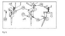
- a cantilever (27) is retracted into a fixed opening (28) of the tool (26), the opening and the cantilever forming a fulcrum so that by changing the position of the tool (26) in the Z-axis ( 29) an angle of inclination is adjusted and the tool is locked in this position by a mutually moving surfaces coincident spring (30).
- a tool changer system with two pins 3 which serve as a coupling element and at the same time as electrical contacts between the attached to the Z-axis 5 tool holder 6 and the tool 4.
- the tool holder 6 is attached to the robot arm 1. Stopping tools are stored in the parking position 7.
- the tilting device for MTPs in Fig. 2a consists of a base plate 13 which has side 11 and rear 14 locking nipple, which fix and guide the MTPs.
- the lifter 8 is approached by the robot arm and by means of a Lifting tool 16 shifted in the vertical direction.
- the tilted MTP is held by frictionally supporting the lifter via a plastic plate 9, which experiences a constant force which is induced by a spring-loaded screw 10.
- the bottom plate also contains recesses with magnets 12, with corresponding counter magnets are embedded in the worktop of the robot.
- the tilting device, or any other elements such as pipette racks, tub holders, etc., locked and held.
- the robot arm can pick up the pipette tool 18 from the tool holder 7 and suck out media from the wells almost without residue (at the lowest point) due to the tilt angle.
- the worktop of the robot in Fig. 3 consists of an easy-to-clean sheet metal. Under the bottom plate, a grid of strong permanent magnets 19 is arranged. The magnets can be glued from below or fixed via a mask attached underneath.
- the applied on the robot platform applications such as MTP tilting stations, pipette racks, storage vessels contain in turn also fixed to the underside of permanent magnets with the same grid dimensions, such as the magnetron under the floor panel, so that they are exactly on top of each other. As a result, an automatic locking and fixing of the applications is achieved.
- the robotic arm is also used for refilling media tubes Fig. 4 used.
- Storage bottles are in a cooled environment and are, for example, subjected to pressure which causes medium to be forced into the medium tube connected to the supply bottles by a tube.
- a hose clamp 20 acts as a valve.
- the hose clamp is clamped on one side and presses on a bolt 19a due to a defined spring force.
- bolt 19a and hose clamp 20 the hose, in the closed state of the valve, disconnected and leaves no liquid through.
- the robot arm is moved to the opposite end of the clamping, so that the hose clamp lifts off due to the introduction of force at the nip at the pin and the hose 25 no longer squeezed together.
- the medium Due to the applied pressure in the storage vessels, the medium is now through the Hose pressed and introduced via a fixed tube 21 in the media tube 22, which sits in a tempering 23. If enough medium has been passed into the media tube, then the robot arm moves back so that the inlet hose 25 is disconnected again by the restoring force.
- Fig. 5 is located on the adjustable in at least one axis pipette holder 26, a boom 27, for example in the form of a rod.
- the cantilever is fixed at the forward end by retracting into a fixed aperture 28, this aperture forming, for example, with the rounded end of the rod, a ball and socket pivot which ensures a large range of movement (in this case up to 130 °) in all directions ,
- a ball and socket pivot which ensures a large range of movement (in this case up to 130 °) in all directions .
- the locked position is ensured by a mutually moving surfaces fauxpressenden spring 30, which prevents the induction of friction that the rotated pipette head by itself falls back into the starting position.
Landscapes
- Engineering & Computer Science (AREA)
- Robotics (AREA)
- Mechanical Engineering (AREA)
- Analytical Chemistry (AREA)
- Life Sciences & Earth Sciences (AREA)
- Chemical & Material Sciences (AREA)
- Health & Medical Sciences (AREA)
- Biochemistry (AREA)
- General Health & Medical Sciences (AREA)
- General Physics & Mathematics (AREA)
- Immunology (AREA)
- Pathology (AREA)
- Physics & Mathematics (AREA)
- Manipulator (AREA)
Applications Claiming Priority (1)
| Application Number | Priority Date | Filing Date | Title |
|---|---|---|---|
| DE102012105241A DE102012105241A1 (de) | 2012-06-15 | 2012-06-15 | Roboter mit Werkzeugwechsler |
Publications (2)
| Publication Number | Publication Date |
|---|---|
| EP2674264A2 true EP2674264A2 (fr) | 2013-12-18 |
| EP2674264A3 EP2674264A3 (fr) | 2017-01-04 |
Family
ID=48670395
Family Applications (1)
| Application Number | Title | Priority Date | Filing Date |
|---|---|---|---|
| EP13172056.7A Withdrawn EP2674264A3 (fr) | 2012-06-15 | 2013-06-14 | Robot doté d'un changeur d'outil |
Country Status (2)
| Country | Link |
|---|---|
| EP (1) | EP2674264A3 (fr) |
| DE (1) | DE102012105241A1 (fr) |
Cited By (12)
| Publication number | Priority date | Publication date | Assignee | Title |
|---|---|---|---|---|
| CN107433214A (zh) * | 2017-08-17 | 2017-12-05 | 成都润伯科技有限公司 | 一种全自动移液工作站及其移液控制方法 |
| CN108297122A (zh) * | 2018-01-31 | 2018-07-20 | 深圳市德富莱智能科技股份有限公司 | 快换保压夹爪 |
| US20210156851A1 (en) * | 2019-11-22 | 2021-05-27 | Western Digital Technologies, Inc. | Magnetic gradient concentrator/reluctance detector for molecule detection |
| US20220241871A1 (en) * | 2021-02-03 | 2022-08-04 | Smc Corporation | Chuck apparatus |
| WO2022256634A1 (fr) * | 2021-06-04 | 2022-12-08 | Advanced Solutions Life Sciences, Llc | Platines inclinables et leurs procédés d'utilisation |
| US11609208B2 (en) | 2019-04-12 | 2023-03-21 | Western Digital Technologies, Inc. | Devices and methods for molecule detection based on thermal stabilities of magnetic nanoparticles |
| CN116638546A (zh) * | 2023-04-04 | 2023-08-25 | 山东源顺智能科技有限公司 | 高精械架机械手及工作方法 |
| US11738336B2 (en) | 2019-04-12 | 2023-08-29 | Western Digital Technologies, Inc. | Spin torque oscillator (STO) sensors used in nucleic acid sequencing arrays and detection schemes for nucleic acid sequencing |
| US11932904B2 (en) | 2019-09-13 | 2024-03-19 | Western Digital Technologies, Inc. | Enhanced optical detection for nucleic acid sequencing using thermally-dependent fluorophore tags |
| US12121896B2 (en) | 2019-04-12 | 2024-10-22 | Roche Sequencing Solutions, Inc. | Nucleic acid sequencing by synthesis using magnetic sensor arrays |
| US12241950B2 (en) | 2019-04-12 | 2025-03-04 | Western Digital Technologies, Inc. | Magnetoresistive sensor array for molecule detection and related detection schemes |
| US12306179B2 (en) | 2019-04-12 | 2025-05-20 | Western Digital Technologies, Inc. | Thermal sensor array for molecule detection and related detection schemes |
Families Citing this family (1)
| Publication number | Priority date | Publication date | Assignee | Title |
|---|---|---|---|---|
| EP3441740B1 (fr) * | 2016-04-07 | 2020-09-23 | Tanabe Engineering Corporation | Collecteur de poudre, dispositif de collecte de poudre et système de collecte de poudre automatique |
Family Cites Families (5)
| Publication number | Priority date | Publication date | Assignee | Title |
|---|---|---|---|---|
| SE453168B (sv) * | 1982-04-19 | 1988-01-18 | Lennart Palmer | Anordning for att utbytbart anordna verktyg pa en industrirobot |
| US5145227A (en) * | 1990-12-31 | 1992-09-08 | The United States Of America As Represented By The Administrator Of The National Aeronautics And Space Administration | Electromagnetic attachment mechanism |
| DE4306586A1 (de) * | 1993-03-03 | 1994-09-08 | Deutsches Rotes Kreuz Blutspen | Verfahren zur photometrischen Erfassung einer Agglutinationsreaktion |
| SE512397C2 (sv) * | 1998-05-20 | 2000-03-13 | Alfa Laval Agri Ab | Dockningsanordning |
| WO2006075201A1 (fr) * | 2004-09-08 | 2006-07-20 | Pfizer Products Inc. | Systeme automatique pour manipuler et peser des quantites analytiques de substances a particules |
-
2012
- 2012-06-15 DE DE102012105241A patent/DE102012105241A1/de not_active Withdrawn
-
2013
- 2013-06-14 EP EP13172056.7A patent/EP2674264A3/fr not_active Withdrawn
Cited By (15)
| Publication number | Priority date | Publication date | Assignee | Title |
|---|---|---|---|---|
| CN107433214A (zh) * | 2017-08-17 | 2017-12-05 | 成都润伯科技有限公司 | 一种全自动移液工作站及其移液控制方法 |
| CN108297122A (zh) * | 2018-01-31 | 2018-07-20 | 深圳市德富莱智能科技股份有限公司 | 快换保压夹爪 |
| US12121896B2 (en) | 2019-04-12 | 2024-10-22 | Roche Sequencing Solutions, Inc. | Nucleic acid sequencing by synthesis using magnetic sensor arrays |
| US12306179B2 (en) | 2019-04-12 | 2025-05-20 | Western Digital Technologies, Inc. | Thermal sensor array for molecule detection and related detection schemes |
| US11609208B2 (en) | 2019-04-12 | 2023-03-21 | Western Digital Technologies, Inc. | Devices and methods for molecule detection based on thermal stabilities of magnetic nanoparticles |
| US12241950B2 (en) | 2019-04-12 | 2025-03-04 | Western Digital Technologies, Inc. | Magnetoresistive sensor array for molecule detection and related detection schemes |
| US11738336B2 (en) | 2019-04-12 | 2023-08-29 | Western Digital Technologies, Inc. | Spin torque oscillator (STO) sensors used in nucleic acid sequencing arrays and detection schemes for nucleic acid sequencing |
| US12163921B2 (en) | 2019-04-12 | 2024-12-10 | Western Digital Technologies, Inc. | Based on thermal stabilities of magnetic nanoparticles |
| US11932904B2 (en) | 2019-09-13 | 2024-03-19 | Western Digital Technologies, Inc. | Enhanced optical detection for nucleic acid sequencing using thermally-dependent fluorophore tags |
| US20210156851A1 (en) * | 2019-11-22 | 2021-05-27 | Western Digital Technologies, Inc. | Magnetic gradient concentrator/reluctance detector for molecule detection |
| US11747329B2 (en) * | 2019-11-22 | 2023-09-05 | Western Digital Technologies, Inc. | Magnetic gradient concentrator/reluctance detector for molecule detection |
| US20220241871A1 (en) * | 2021-02-03 | 2022-08-04 | Smc Corporation | Chuck apparatus |
| US12083523B2 (en) | 2021-06-04 | 2024-09-10 | Advanced Solutions Life Sciences, Llc | Tiltable stages and methods of using the same |
| WO2022256634A1 (fr) * | 2021-06-04 | 2022-12-08 | Advanced Solutions Life Sciences, Llc | Platines inclinables et leurs procédés d'utilisation |
| CN116638546A (zh) * | 2023-04-04 | 2023-08-25 | 山东源顺智能科技有限公司 | 高精械架机械手及工作方法 |
Also Published As
| Publication number | Publication date |
|---|---|
| DE102012105241A1 (de) | 2013-12-19 |
| EP2674264A3 (fr) | 2017-01-04 |
Similar Documents
| Publication | Publication Date | Title |
|---|---|---|
| EP2674264A2 (fr) | Robot doté d'un changeur d'outil | |
| EP3606689B1 (fr) | Procédé d'alimentation en rivets d'une riveuse | |
| EP2078961B1 (fr) | Dispositif de manipulation d'échantillons de laboratoire | |
| DE10247731A1 (de) | Greifwerkzeug, Dosierwerkzeug und Werkzeughalter für einen Laborautomaten | |
| EP0601213A1 (fr) | Dispositif de transport de matières | |
| EP2698234A2 (fr) | Dispositif de prélèvement automatisée de pièces agencées dans un récipient | |
| EP2607029A1 (fr) | Système de changement d'outils | |
| DE202013003510U1 (de) | Manipulatorvorrichtung | |
| DE102011108537A1 (de) | Positioniereinrichtung für eine Laborvorrichtung zum Verteilen fluider Proben, Laborvorrichtung mit Positioniereinrichtung und Verfahren zum Positionieren | |
| DE102014008444A1 (de) | Vorrichtung zum automatisierten Entnehmen von in einem Behälter angeordneten Werkstücken | |
| CH706811A1 (de) | Mikroplatten-Reader mit Deckelabheber für Mikroplatten. | |
| DE102008023093A1 (de) | Vorrichtung zum Blocken von Werkstücken, insbesondere Brillengläsern, für deren Bearbeitung und/oder Beschichtung | |
| EP2708335A1 (fr) | Système de changement de pince à grande vitesse | |
| DE102015210842B3 (de) | Vorrichtung und Verfahren zum Greifen, Vereinzeln, Transportieren und/oder Ablegen von verschlossenen und/oder unverschlossenen Petrischalen | |
| DE102016205612B4 (de) | Halteeinrichtung | |
| DE102017114971A1 (de) | Nietelementversorgungseinheit | |
| EP1570714A1 (fr) | Unite de prehension pour la mise en place de composants electriques sur des substrats | |
| DE102007018483B4 (de) | Träger zum Positionieren von Objekten gegenüber Laborartikeln | |
| EP1731452A2 (fr) | Moyen de prise de charge | |
| EP4281257A1 (fr) | Système de préparation de commandes | |
| DE102015100637B4 (de) | Vorrichtung zum automatischen Durchführen chemischer und biologischer Verfahren in Gefäßplatten | |
| EP1291648B1 (fr) | Boîtier à encombrement réduit pour un appareil à rayons x avec changeur d'échantillons | |
| AT524549B1 (de) | Industrieofenanlage | |
| DE102022200781B4 (de) | Roboterhand | |
| DE102015112566A1 (de) | Bauteilehandhabungsvorrichtung, Verfahren zum Fördern von Bauteilen und System |
Legal Events
| Date | Code | Title | Description |
|---|---|---|---|
| PUAI | Public reference made under article 153(3) epc to a published international application that has entered the european phase |
Free format text: ORIGINAL CODE: 0009012 |
|
| AK | Designated contracting states |
Kind code of ref document: A2 Designated state(s): AL AT BE BG CH CY CZ DE DK EE ES FI FR GB GR HR HU IE IS IT LI LT LU LV MC MK MT NL NO PL PT RO RS SE SI SK SM TR |
|
| AX | Request for extension of the european patent |
Extension state: BA ME |
|
| PUAL | Search report despatched |
Free format text: ORIGINAL CODE: 0009013 |
|
| AK | Designated contracting states |
Kind code of ref document: A3 Designated state(s): AL AT BE BG CH CY CZ DE DK EE ES FI FR GB GR HR HU IE IS IT LI LT LU LV MC MK MT NL NO PL PT RO RS SE SI SK SM TR |
|
| AX | Request for extension of the european patent |
Extension state: BA ME |
|
| RIC1 | Information provided on ipc code assigned before grant |
Ipc: B25J 15/04 20060101AFI20161128BHEP Ipc: G01N 35/00 20060101ALI20161128BHEP |
|
| 17P | Request for examination filed |
Effective date: 20170729 |
|
| RBV | Designated contracting states (corrected) |
Designated state(s): AL AT BE BG CH CY CZ DE DK EE ES FI FR GB GR HR HU IE IS IT LI LT LU LV MC MK MT NL NO PL PT RO RS SE SI SK SM TR |
|
| STAA | Information on the status of an ep patent application or granted ep patent |
Free format text: STATUS: THE APPLICATION IS DEEMED TO BE WITHDRAWN |
|
| 18D | Application deemed to be withdrawn |
Effective date: 20190103 |