EP2674285A1 - Procédé et outil de conformité pour la fabrication de pièces de matériau composite avec une haute précision dimensionnelle - Google Patents
Procédé et outil de conformité pour la fabrication de pièces de matériau composite avec une haute précision dimensionnelle Download PDFInfo
- Publication number
- EP2674285A1 EP2674285A1 EP12382241.3A EP12382241A EP2674285A1 EP 2674285 A1 EP2674285 A1 EP 2674285A1 EP 12382241 A EP12382241 A EP 12382241A EP 2674285 A1 EP2674285 A1 EP 2674285A1
- Authority
- EP
- European Patent Office
- Prior art keywords
- piece
- cradle
- composite material
- force applying
- conforming
- Prior art date
- Legal status (The legal status is an assumption and is not a legal conclusion. Google has not performed a legal analysis and makes no representation as to the accuracy of the status listed.)
- Withdrawn
Links
- 238000000034 method Methods 0.000 title claims abstract description 36
- 239000002131 composite material Substances 0.000 title claims abstract description 29
- 238000004519 manufacturing process Methods 0.000 title claims abstract description 24
- 238000010438 heat treatment Methods 0.000 claims abstract description 7
- 239000000463 material Substances 0.000 claims description 13
- 230000033001 locomotion Effects 0.000 claims description 10
- 229920005989 resin Polymers 0.000 claims description 9
- 239000011347 resin Substances 0.000 claims description 9
- 239000002952 polymeric resin Substances 0.000 claims description 6
- 229920003002 synthetic resin Polymers 0.000 claims description 6
- 229910001374 Invar Inorganic materials 0.000 claims description 5
- 230000002787 reinforcement Effects 0.000 claims description 5
- 239000004634 thermosetting polymer Substances 0.000 claims description 5
- 239000000835 fiber Substances 0.000 claims description 4
- 230000000694 effects Effects 0.000 abstract description 7
- 238000002347 injection Methods 0.000 description 3
- 239000007924 injection Substances 0.000 description 3
- 230000006835 compression Effects 0.000 description 2
- 238000007906 compression Methods 0.000 description 2
- 230000003071 parasitic effect Effects 0.000 description 2
- 239000000243 solution Substances 0.000 description 2
- 229910000831 Steel Inorganic materials 0.000 description 1
- 238000005452 bending Methods 0.000 description 1
- 230000005540 biological transmission Effects 0.000 description 1
- 230000000295 complement effect Effects 0.000 description 1
- 239000003822 epoxy resin Substances 0.000 description 1
- 229920000647 polyepoxide Polymers 0.000 description 1
- 229920005594 polymer fiber Polymers 0.000 description 1
- 238000011084 recovery Methods 0.000 description 1
- 230000002269 spontaneous effect Effects 0.000 description 1
- 239000010959 steel Substances 0.000 description 1
- 238000001721 transfer moulding Methods 0.000 description 1
Images




Classifications
-
- B—PERFORMING OPERATIONS; TRANSPORTING
- B29—WORKING OF PLASTICS; WORKING OF SUBSTANCES IN A PLASTIC STATE IN GENERAL
- B29C—SHAPING OR JOINING OF PLASTICS; SHAPING OF MATERIAL IN A PLASTIC STATE, NOT OTHERWISE PROVIDED FOR; AFTER-TREATMENT OF THE SHAPED PRODUCTS, e.g. REPAIRING
- B29C37/00—Component parts, details, accessories or auxiliary operations, not covered by group B29C33/00 or B29C35/00
- B29C37/005—Compensating volume or shape change during moulding, in general
-
- B—PERFORMING OPERATIONS; TRANSPORTING
- B29—WORKING OF PLASTICS; WORKING OF SUBSTANCES IN A PLASTIC STATE IN GENERAL
- B29C—SHAPING OR JOINING OF PLASTICS; SHAPING OF MATERIAL IN A PLASTIC STATE, NOT OTHERWISE PROVIDED FOR; AFTER-TREATMENT OF THE SHAPED PRODUCTS, e.g. REPAIRING
- B29C35/00—Heating, cooling or curing, e.g. crosslinking or vulcanising; Apparatus therefor
- B29C35/02—Heating or curing, e.g. crosslinking or vulcanizing during moulding, e.g. in a mould
-
- B—PERFORMING OPERATIONS; TRANSPORTING
- B29—WORKING OF PLASTICS; WORKING OF SUBSTANCES IN A PLASTIC STATE IN GENERAL
- B29C—SHAPING OR JOINING OF PLASTICS; SHAPING OF MATERIAL IN A PLASTIC STATE, NOT OTHERWISE PROVIDED FOR; AFTER-TREATMENT OF THE SHAPED PRODUCTS, e.g. REPAIRING
- B29C70/00—Shaping composites, i.e. plastics material comprising reinforcements, fillers or preformed parts, e.g. inserts
- B29C70/04—Shaping composites, i.e. plastics material comprising reinforcements, fillers or preformed parts, e.g. inserts comprising reinforcements only, e.g. self-reinforcing plastics
- B29C70/28—Shaping operations therefor
- B29C70/40—Shaping or impregnating by compression not applied
- B29C70/42—Shaping or impregnating by compression not applied for producing articles of definite length, i.e. discrete articles
- B29C70/44—Shaping or impregnating by compression not applied for producing articles of definite length, i.e. discrete articles using isostatic pressure, e.g. pressure difference-moulding, vacuum bag-moulding, autoclave-moulding or expanding rubber-moulding
- B29C70/446—Moulding structures having an axis of symmetry or at least one channel, e.g. tubular structures, frames
-
- B—PERFORMING OPERATIONS; TRANSPORTING
- B29—WORKING OF PLASTICS; WORKING OF SUBSTANCES IN A PLASTIC STATE IN GENERAL
- B29K—INDEXING SCHEME ASSOCIATED WITH SUBCLASSES B29B, B29C OR B29D, RELATING TO MOULDING MATERIALS OR TO MATERIALS FOR MOULDS, REINFORCEMENTS, FILLERS OR PREFORMED PARTS, e.g. INSERTS
- B29K2105/00—Condition, form or state of moulded material or of the material to be shaped
- B29K2105/24—Condition, form or state of moulded material or of the material to be shaped crosslinked or vulcanised
- B29K2105/243—Partially cured
-
- B—PERFORMING OPERATIONS; TRANSPORTING
- B29—WORKING OF PLASTICS; WORKING OF SUBSTANCES IN A PLASTIC STATE IN GENERAL
- B29L—INDEXING SCHEME ASSOCIATED WITH SUBCLASS B29C, RELATING TO PARTICULAR ARTICLES
- B29L2031/00—Other particular articles
- B29L2031/30—Vehicles, e.g. ships or aircraft, or body parts thereof
- B29L2031/3076—Aircrafts
- B29L2031/3082—Fuselages
Definitions
- the present invention relates to a method for manufacturing pieces made of composite material with demanding dimensional tolerances (HARTM) and a conforming tool for implementing this method.
- HARTM dimensional tolerances
- the main field of application of the present invention is the field of the manufacture of aeronautical structures.
- the method described in this invention is carried out in two main steps.
- the first main step of the manufacturing method is to pack the layers that constitute the piece and launch the curing process. Said curing process begins with a partial curing of the piece, obtaining as a result pieces which are apparently finished. As it also happens in the conventional full curing cycle, these pieces have the mentioned springback.
- the pieces are subjected at the same time to a combination of a high accuracy conforming process and the completion of the curing in order to achieve the final shape of them.
- document WO 2008/012378 A1 describes a method for producing a piece of composite material made with a polymeric resin and fiber reinforcement from at least two subcomponents which comprises two curing cycles.
- This document describes a manufacturing process to integrate several parts of composite material in two steps, however this is not the object of the present invention.
- the object of the present invention is to provide a manufacturing method of high accuracy aeronautical pieces made of composite material that eliminates the "springback" problem while represents an important saving in terms of manufacturing and assembly time and cost.
- the invention consists of a manufacturing method of pieces of composite material with high dimensional accuracy; a device to implement this method is also disclosed. These pieces will be preferably long pieces or thin panels and the composite material shall be preferably made of at least one polymer resin and one fiber reinforcement.
- a first object of the present invention is a manufacturing method of pieces of composite material that comprises at least the following stages:
- the piece obtained, with the final shape and completely cured has a high dimensional quality.
- Said conforming tool for carrying out the procedure described above it is also disclosed.
- Said conforming tool at least comprises:
- the present invention has foreseen another preferred embodiment that comprises a rigid frame of steel, which is cheaper than invar, a thinner cradle of, for example, invar, relative motion means between the frame and the cradle, and force applying means which compress the piece against the cradle.
- This hybrid solution reduces considerably the final cost of the conforming tool since the material used in the manufacture of the cradle is very expensive and this hybrid solution reduces the thickness of the cradle by using a frame which is made of a more conventional and cheaper material.
- the lower planar surface of the cradle is free to move on the upper planar surface of the frame.
- the relative motion means placed between the frame and the cradle avoid the generation and transmission of forces between the frame and the cradle.
- this relative motion means are rollers.
- the force applying means are either point force applying means which introduce the force generated in different points of the piece or distributed force applying means.
- the point force applying means are at least three force applying modules.
- each one of the force applying modules comprises:
- the distributed force applying means are a vacuum bag, inside which the piece is introduced. This vacuum bag, once the vacuum is created, pushes the piece against the cradle by applying the force generated in a distributed way.
- the distributed force applying means is a bladder placed between the piece and a confining element. This bladder, once inflated, pushes the piece against the cradle.
- the present invention has foreseen two different embodiments for linking the force applying modules to the tool.
- the first embodiment has foreseen that the linkage assembly attaches the force applying module directly to the cradle.
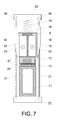
- the second embodiment has foreseen that, if the conforming tool comprises a frame, relative motion means and a cradle, the linkage assembly attaches the force applying modules to the frame by interposition of at least one isostatic link. These isostatic links do not transmit loads in the direction of the lower planar surface of the cradle. This second embodiment is shown in figures 5 to 7 of the present description.
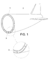
- Figure 1 shows in a simple and general way, how the springback (3) affects to the accuracy in the assembly of the different sections of a frame (1) in an aircraft (2).
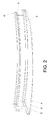
- figure 2 is shown in detail how the springback affects to a beam with asymmetrical profile being the desired beam free of springback drawn in continuous line (5) and the manufactured beams drawn in dotted line (4, 4').
- the beams drawn in dotted line (4,4') are affected, in both cases, by the springback effect since the manufactured beams have a curvature that it is not the desired.
- the mold (6,7) is heated and the resin is injected through the resin inlet port (8b) and the air is removed through the air outlet port (8a). Once the cycle has finished the piece cools down until it reaches the optimal temperature for its demolding.
- the obtained piece (9) is, as shown in figure 4 which is an example of the embodiment of the present invention, a curved beam of 3 or 4 meters in length and with an asymmetric profile.
- This beam (9) suffers the springback effect.
- the demolded partially cured beam (9) has the appearance of a cured piece but due to the partial curing process this beam (9) still allows a later small dimensional correction.
- the beam (9) is placed into a conforming tool (10) for giving it the final shape.
- the main body of the conforming tool (10) is formed by a frame (11) of a length similar to the length of the beam (9) to be conformed and much more rigid in flexion than said beam (9) and a cradle (12) made of a material with a coefficient of thermal expansion similar to the coefficient of thermal expansion of the composite material, as for example, invar.
- the cradle (12) must be made of this kind of material in order to not suffer deformations, especially in the longitudinal axis, during the heating process of the conforming tool (10).
- relative motion means (13) between the frame (11) and the cradle (12) have been placed.
- these relative motion means (13) which allow the free longitudinal movement of the lower planar surface (27) of the cradle (12) on the upper planar surface (28) of the frame (11), may be rollers.
- the present embodiment of the invention avoids the generation of undesired longitudinal loads between these two parts of the conforming tool.
- the beam (9) is fixed to the conforming tool (10) by the force applying modules (14) which in turn integrate clamping units that firmly attach the force applying modules to the beam (9). These clamping units also distribute the load generated during the conforming process along the surface in contact with the beam (9).
- the load is generated by a spring (19) which in turn controls the application of the load on the beam allowing it to maintain said load nearly constant during the conforming process.
- the force applying modules (14) are placed along the beam. In a preferred embodiment of the invention these force applying modules (14) are three, but their number will depend on the length and the desired geometry of the beam (9).
- These clamping units which are integrated in the force applying modules (14), comprise one bladder (15) placed at each side of the central portion of the beam (9).
- the bladders (15) have a metallic piece (16) on their outer surface that actuates as a mechanical boundary and an inlet pressure port (17) through which compressed air is introduced.
- An injector (23) is connected to inlet pressure port (17) through which pressure air is injected, the air coming through air ducts (24) (the air pressure generator is an external device not shown in the figures).
- the assembly formed by the beam (9) and the two bladders (15) is confined by a yoke (18).
- the objective of the bladders (15) is, once they are inflated, to confine firmly the beam (9) having, at the same time, a soft contact with the beam surface avoiding deformations and scratches generated by the loads applied on the beam (9).
- the force applying modules (14) also comprises the spring (19) which is placed between the yoke (18) and an upper fixing piece (20). At both ends of the upper fixing piece (20) is placed an isostatic link (21), as for example a rod, whose upper end is threaded. The lower end of the rods is fixed to a lower fixing piece (22). This lower fixing end is placed under the lower face of the frame (11).
- the spring (19) is loaded by means of a couple of nuts (26) which turn along the thread of the isostatic links (21). The load generated by the spring is transmitted to the beam (9) during the conforming process.
- the second curing stage is carried out in an oven. After forces are applied on the beam (9), the conforming tool (10) and the beam (9) are introduced into the oven.
- the mechanical loads transmitted by the compression elements such as the compression springs (19) of the force applying modules (14), deform the beam (9) in the perpendicular axis, with respect to the longitudinal axis of the beam (9), until the lower face of the beam (9) is completely adapted to the upper face of the cradle (12).
- FIG 8 it is shown a perspective view of a particular embodiment of the conforming tool object of the present invention.
- the beam (9) is confined by means of a confining element (29), which could be a bladder, placed at each side of the central portion of the beam (9).
- the confining elements (29) have a metallic piece (36) on their outer surface that actuates as a mechanical boundary.
- a bladder (30) Over the upper surface of the beam (9) is placed another bladder (30) which, once inflated with pressure air, is in charge of creating a pressure, perpendicular to the longitudinal axis of the beam (9), that pushes the beam against the cradle (31).
- the beam (9), the confining elements (29), the metallic pieces (36) and the bladder (30) are confined by means of a yoke (32) along the entire beam (9).
- the confining elements (29), the yoke (32), the metallic pieces (36) and the bladder (30) have at least the length of the beam (9) in such a way that the pressure generated by the bladder (30), once inflated, is transmitted to the beam (9).
- the yoke (32) comprises, at both ends, an upper fixing piece (33) that has threaded at both ends of it an isostatic link (34), as for example a rod.
- the lower end of the isostatic link (34) will be fixed directly to the cradle (31) or to any other part of the conforming tool.
- several secondary reinforcements (35) have been placed along the yoke.
- FIG 9 is shown in detail how the springback affects to a panel with a pair of swagged cutouts (39), being the desired panel free of springback drawn in continuous line (38) and the manufactured panel drawn in dotted line (37).
- the panel drawn in dotted line (37) is affected by the springback effect since the manufactured panel has a shape that it is not the desired.
- FIG 10 is shown the panel (37) that suffers deformation due to the springback effect, inside of a vacuum bag (40).
- This vacuum bag (40) is fixed to the cradle (41) and once the panel (37) is placed inside and the bag (40) is sealed, the air is removed trough an outlet port (42).
- the vacuum bag (40) generates a distributed force on the upper surface of the panel (37) that pushes the lower face of the panel (37) against the upper surface of the cradle (41), conforming in this way the panel.
- the obtained panel is the panel (38) drawn in continuous line in figure 9 free of springback effect.
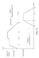
- FIG 11 is shown a particular curing cycle of a piece made with a thermoset resin.
- the first curing cycle of the piece disclosed in the present invention is shown.
- T injection temperature of injection
- T first curing first curing temperature
- T demoulding suitable temperature to be demolded
- the lower part of the graph of figure 11 shows the second curing cycle of the piece, once demolded from the RTM mold, during which the mentioned piece is conformed.
- the described method entails a significant saving of time in the manufacture and assembly processes of pieces.
Landscapes
- Physics & Mathematics (AREA)
- Health & Medical Sciences (AREA)
- Oral & Maxillofacial Surgery (AREA)
- Thermal Sciences (AREA)
- Chemical & Material Sciences (AREA)
- Engineering & Computer Science (AREA)
- Composite Materials (AREA)
- Mechanical Engineering (AREA)
- Moulding By Coating Moulds (AREA)
Priority Applications (1)
| Application Number | Priority Date | Filing Date | Title |
|---|---|---|---|
| EP12382241.3A EP2674285A1 (fr) | 2012-06-15 | 2012-06-15 | Procédé et outil de conformité pour la fabrication de pièces de matériau composite avec une haute précision dimensionnelle |
Applications Claiming Priority (1)
| Application Number | Priority Date | Filing Date | Title |
|---|---|---|---|
| EP12382241.3A EP2674285A1 (fr) | 2012-06-15 | 2012-06-15 | Procédé et outil de conformité pour la fabrication de pièces de matériau composite avec une haute précision dimensionnelle |
Publications (1)
| Publication Number | Publication Date |
|---|---|
| EP2674285A1 true EP2674285A1 (fr) | 2013-12-18 |
Family
ID=46319672
Family Applications (1)
| Application Number | Title | Priority Date | Filing Date |
|---|---|---|---|
| EP12382241.3A Withdrawn EP2674285A1 (fr) | 2012-06-15 | 2012-06-15 | Procédé et outil de conformité pour la fabrication de pièces de matériau composite avec une haute précision dimensionnelle |
Country Status (1)
| Country | Link |
|---|---|
| EP (1) | EP2674285A1 (fr) |
Cited By (1)
| Publication number | Priority date | Publication date | Assignee | Title |
|---|---|---|---|---|
| CN111531387A (zh) * | 2020-06-10 | 2020-08-14 | 哈尔滨新科锐工艺装备制造有限公司 | 航空用复合材料部件胶接与铆接工装及制造方法 |
Citations (6)
| Publication number | Priority date | Publication date | Assignee | Title |
|---|---|---|---|---|
| US20040247882A1 (en) * | 2001-11-07 | 2004-12-09 | Shinji Kouchi | Epoxy resin compositions for fiber-reinforced composite materials, process for production of the materials and fiber-reinforced composite materials |
| WO2008012378A1 (fr) | 2006-07-28 | 2008-01-31 | Airbus España, S.L. | Procédé de fabrication de pièces de matériaux composés en deux cycles de cuisson |
| US20100295210A1 (en) * | 2007-10-31 | 2010-11-25 | Airbus Operations Sas | Method of producing a structural part made from a thermosetting resin by drawing |
| US20110143100A1 (en) * | 2008-09-04 | 2011-06-16 | Airbus Operations Limited | Assembling and shaping laminate panel |
| DE102010010802A1 (de) * | 2010-03-09 | 2011-09-15 | Fraunhofer-Gesellschaft zur Förderung der angewandten Forschung e.V. | Verfahren zur Herstellung von faserverstärkten Polymer-Formteilen |
| US20110259508A1 (en) * | 2007-09-20 | 2011-10-27 | Alenia Aeronautica S.P.A. | method of manufcturing a curved structural element made of composite material and having a complex, open cross-section |
-
2012
- 2012-06-15 EP EP12382241.3A patent/EP2674285A1/fr not_active Withdrawn
Patent Citations (6)
| Publication number | Priority date | Publication date | Assignee | Title |
|---|---|---|---|---|
| US20040247882A1 (en) * | 2001-11-07 | 2004-12-09 | Shinji Kouchi | Epoxy resin compositions for fiber-reinforced composite materials, process for production of the materials and fiber-reinforced composite materials |
| WO2008012378A1 (fr) | 2006-07-28 | 2008-01-31 | Airbus España, S.L. | Procédé de fabrication de pièces de matériaux composés en deux cycles de cuisson |
| US20110259508A1 (en) * | 2007-09-20 | 2011-10-27 | Alenia Aeronautica S.P.A. | method of manufcturing a curved structural element made of composite material and having a complex, open cross-section |
| US20100295210A1 (en) * | 2007-10-31 | 2010-11-25 | Airbus Operations Sas | Method of producing a structural part made from a thermosetting resin by drawing |
| US20110143100A1 (en) * | 2008-09-04 | 2011-06-16 | Airbus Operations Limited | Assembling and shaping laminate panel |
| DE102010010802A1 (de) * | 2010-03-09 | 2011-09-15 | Fraunhofer-Gesellschaft zur Förderung der angewandten Forschung e.V. | Verfahren zur Herstellung von faserverstärkten Polymer-Formteilen |
Non-Patent Citations (1)
| Title |
|---|
| DUGMORE A ET AL: "Behind every good part is a great tool", REINFORCED PLASTICS, ELSEVIER ADVANCED TECHNOLOGY, NEW YORK, NY, US, vol. 53, no. 2, 1 March 2009 (2009-03-01), pages 22 - 25, XP026266234, ISSN: 0034-3617, [retrieved on 20090301], DOI: 10.1016/S0034-3617(09)70079-7 * |
Cited By (1)
| Publication number | Priority date | Publication date | Assignee | Title |
|---|---|---|---|---|
| CN111531387A (zh) * | 2020-06-10 | 2020-08-14 | 哈尔滨新科锐工艺装备制造有限公司 | 航空用复合材料部件胶接与铆接工装及制造方法 |
Similar Documents
| Publication | Publication Date | Title |
|---|---|---|
| US9238335B2 (en) | Mandrel for autoclave curing applications | |
| US9573355B2 (en) | Method and apparatus for contouring composite pre-preg articles | |
| EP3006180B1 (fr) | Procédé et dispositif pour la fabrication d'un plastique renforcé par des fibres | |
| JP6563284B2 (ja) | 繊維強化プラスチック成型品の製造装置及びその製造方法 | |
| CN102015261B (zh) | 用于模制由复合材料制成的弯曲部件的方法和设备以及相应的部件 | |
| US8758664B2 (en) | Method for forming composite components and tool for use therein | |
| US20100006739A1 (en) | Composite Mandrel For Autoclave Curing Applications | |
| CN111993682B (zh) | 一种复合材料角条结构件的成型工装及制备方法 | |
| EP2835252A1 (fr) | Outillage et procédé de consolidation de structures composites hautement intégrées | |
| CN112536946B (zh) | 一种使用软模加压的复合材料锥段成型模 | |
| JPH10291258A (ja) | 複合材料でできた精密中空部品の製造方法 | |
| TWI610801B (zh) | 樹脂成形品的製造裝置及製造方法 | |
| CN118789845A (zh) | 基于记忆芯模的复合材料无人机机体成型工装及方法 | |
| JP2954836B2 (ja) | 繊維強化樹脂系型材の成形方法 | |
| EP2674285A1 (fr) | Procédé et outil de conformité pour la fabrication de pièces de matériau composite avec une haute précision dimensionnelle | |
| CN112537435A (zh) | 具有高精度曲面大长径比的复合材料翼梁及其制备方法 | |
| CN110884161A (zh) | 弯曲欧米伽桁条和z形复合材料桁条的制造方法以及具有曲率的复合材料加筋板的制造方法 | |
| CN101171121B (zh) | 将树脂注入到要制造的纤维增强产品的至少一个纤维层内的装置 | |
| CN117799191A (zh) | 一种曲率可设计的混杂对称双稳态结构及其制备方法和应用 | |
| CN109822933A (zh) | 一种用于复合材料结构成型的磁场辅助加压方法 | |
| CN218948194U (zh) | 一种基于记忆芯模的复材进气道产品成型工装 | |
| US11046020B2 (en) | System and method for producing structural thermoplastic parts | |
| RU2829526C2 (ru) | Коробчатая монолитная конструкция из композиционного материала для фюзеляжей и крыльев летательного аппарата и способ изготовления указанной конструкции | |
| CN115052736B (zh) | 原材料成型装置及原材料成型方法 | |
| JP2025506300A (ja) | 湾曲パネルのための鋳型 |
Legal Events
| Date | Code | Title | Description |
|---|---|---|---|
| PUAI | Public reference made under article 153(3) epc to a published international application that has entered the european phase |
Free format text: ORIGINAL CODE: 0009012 |
|
| AK | Designated contracting states |
Kind code of ref document: A1 Designated state(s): AL AT BE BG CH CY CZ DE DK EE ES FI FR GB GR HR HU IE IS IT LI LT LU LV MC MK MT NL NO PL PT RO RS SE SI SK SM TR |
|
| AX | Request for extension of the european patent |
Extension state: BA ME |
|
| STAA | Information on the status of an ep patent application or granted ep patent |
Free format text: STATUS: THE APPLICATION IS DEEMED TO BE WITHDRAWN |
|
| 18D | Application deemed to be withdrawn |
Effective date: 20140619 |