EP2674589B1 - Dispositif de commande pour moteur à combustion interne équipé d'un compresseur volumétrique - Google Patents
Dispositif de commande pour moteur à combustion interne équipé d'un compresseur volumétrique Download PDFInfo
- Publication number
- EP2674589B1 EP2674589B1 EP12744951.0A EP12744951A EP2674589B1 EP 2674589 B1 EP2674589 B1 EP 2674589B1 EP 12744951 A EP12744951 A EP 12744951A EP 2674589 B1 EP2674589 B1 EP 2674589B1
- Authority
- EP
- European Patent Office
- Prior art keywords
- exhaust gas
- pressure
- amount
- intake air
- exhaust
- Prior art date
- Legal status (The legal status is an assumption and is not a legal conclusion. Google has not performed a legal analysis and makes no representation as to the accuracy of the status listed.)
- Not-in-force
Links
- 238000002485 combustion reaction Methods 0.000 title claims description 28
- 230000002000 scavenging effect Effects 0.000 claims description 55
- 230000008859 change Effects 0.000 claims description 34
- 230000001052 transient effect Effects 0.000 claims description 32
- 238000011144 upstream manufacturing Methods 0.000 claims description 5
- 238000001514 detection method Methods 0.000 claims 5
- 238000004364 calculation method Methods 0.000 description 46
- 239000000446 fuel Substances 0.000 description 40
- 239000003054 catalyst Substances 0.000 description 22
- 238000010586 diagram Methods 0.000 description 16
- 238000002347 injection Methods 0.000 description 13
- 239000007924 injection Substances 0.000 description 13
- 230000007246 mechanism Effects 0.000 description 7
- 239000000203 mixture Substances 0.000 description 7
- 230000009471 action Effects 0.000 description 6
- 230000001965 increasing effect Effects 0.000 description 6
- 238000006243 chemical reaction Methods 0.000 description 5
- 230000000694 effects Effects 0.000 description 4
- 229930195733 hydrocarbon Natural products 0.000 description 4
- 150000002430 hydrocarbons Chemical class 0.000 description 4
- 230000000979 retarding effect Effects 0.000 description 4
- OKTJSMMVPCPJKN-UHFFFAOYSA-N Carbon Chemical group [C] OKTJSMMVPCPJKN-UHFFFAOYSA-N 0.000 description 2
- 239000004215 Carbon black (E152) Substances 0.000 description 2
- 230000007423 decrease Effects 0.000 description 2
- 238000000034 method Methods 0.000 description 2
- 230000004913 activation Effects 0.000 description 1
- 238000004891 communication Methods 0.000 description 1
- 230000006835 compression Effects 0.000 description 1
- 238000007906 compression Methods 0.000 description 1
- 230000001934 delay Effects 0.000 description 1
- 238000005516 engineering process Methods 0.000 description 1
- 230000002708 enhancing effect Effects 0.000 description 1
- 230000020169 heat generation Effects 0.000 description 1
- 230000008569 process Effects 0.000 description 1
- 238000000746 purification Methods 0.000 description 1
- 238000009834 vaporization Methods 0.000 description 1
- 230000008016 vaporization Effects 0.000 description 1
Images




Classifications
-
- F—MECHANICAL ENGINEERING; LIGHTING; HEATING; WEAPONS; BLASTING
- F02—COMBUSTION ENGINES; HOT-GAS OR COMBUSTION-PRODUCT ENGINE PLANTS
- F02B—INTERNAL-COMBUSTION PISTON ENGINES; COMBUSTION ENGINES IN GENERAL
- F02B39/00—Component parts, details, or accessories relating to, driven charging or scavenging pumps, not provided for in groups F02B33/00 - F02B37/00
- F02B39/16—Other safety measures for, or other control of, pumps
-
- F—MECHANICAL ENGINEERING; LIGHTING; HEATING; WEAPONS; BLASTING
- F02—COMBUSTION ENGINES; HOT-GAS OR COMBUSTION-PRODUCT ENGINE PLANTS
- F02B—INTERNAL-COMBUSTION PISTON ENGINES; COMBUSTION ENGINES IN GENERAL
- F02B33/00—Engines characterised by provision of pumps for charging or scavenging
-
- F—MECHANICAL ENGINEERING; LIGHTING; HEATING; WEAPONS; BLASTING
- F02—COMBUSTION ENGINES; HOT-GAS OR COMBUSTION-PRODUCT ENGINE PLANTS
- F02D—CONTROLLING COMBUSTION ENGINES
- F02D23/00—Controlling engines characterised by their being supercharged
-
- F—MECHANICAL ENGINEERING; LIGHTING; HEATING; WEAPONS; BLASTING
- F02—COMBUSTION ENGINES; HOT-GAS OR COMBUSTION-PRODUCT ENGINE PLANTS
- F02D—CONTROLLING COMBUSTION ENGINES
- F02D41/00—Electrical control of supply of combustible mixture or its constituents
- F02D41/0002—Controlling intake air
-
- F—MECHANICAL ENGINEERING; LIGHTING; HEATING; WEAPONS; BLASTING
- F02—COMBUSTION ENGINES; HOT-GAS OR COMBUSTION-PRODUCT ENGINE PLANTS
- F02D—CONTROLLING COMBUSTION ENGINES
- F02D45/00—Electrical control not provided for in groups F02D41/00 - F02D43/00
-
- F—MECHANICAL ENGINEERING; LIGHTING; HEATING; WEAPONS; BLASTING
- F02—COMBUSTION ENGINES; HOT-GAS OR COMBUSTION-PRODUCT ENGINE PLANTS
- F02B—INTERNAL-COMBUSTION PISTON ENGINES; COMBUSTION ENGINES IN GENERAL
- F02B37/00—Engines characterised by provision of pumps driven at least for part of the time by exhaust
-
- F—MECHANICAL ENGINEERING; LIGHTING; HEATING; WEAPONS; BLASTING
- F02—COMBUSTION ENGINES; HOT-GAS OR COMBUSTION-PRODUCT ENGINE PLANTS
- F02D—CONTROLLING COMBUSTION ENGINES
- F02D2200/00—Input parameters for engine control
- F02D2200/02—Input parameters for engine control the parameters being related to the engine
- F02D2200/04—Engine intake system parameters
- F02D2200/0406—Intake manifold pressure
-
- F—MECHANICAL ENGINEERING; LIGHTING; HEATING; WEAPONS; BLASTING
- F02—COMBUSTION ENGINES; HOT-GAS OR COMBUSTION-PRODUCT ENGINE PLANTS
- F02D—CONTROLLING COMBUSTION ENGINES
- F02D41/00—Electrical control of supply of combustible mixture or its constituents
- F02D41/02—Circuit arrangements for generating control signals
- F02D41/14—Introducing closed-loop corrections
- F02D41/1438—Introducing closed-loop corrections using means for determining characteristics of the combustion gases; Sensors therefor
- F02D41/1444—Introducing closed-loop corrections using means for determining characteristics of the combustion gases; Sensors therefor characterised by the characteristics of the combustion gases
- F02D41/1448—Introducing closed-loop corrections using means for determining characteristics of the combustion gases; Sensors therefor characterised by the characteristics of the combustion gases the characteristics being an exhaust gas pressure
- F02D41/145—Introducing closed-loop corrections using means for determining characteristics of the combustion gases; Sensors therefor characterised by the characteristics of the combustion gases the characteristics being an exhaust gas pressure with determination means using an estimation
-
- Y—GENERAL TAGGING OF NEW TECHNOLOGICAL DEVELOPMENTS; GENERAL TAGGING OF CROSS-SECTIONAL TECHNOLOGIES SPANNING OVER SEVERAL SECTIONS OF THE IPC; TECHNICAL SUBJECTS COVERED BY FORMER USPC CROSS-REFERENCE ART COLLECTIONS [XRACs] AND DIGESTS
- Y02—TECHNOLOGIES OR APPLICATIONS FOR MITIGATION OR ADAPTATION AGAINST CLIMATE CHANGE
- Y02T—CLIMATE CHANGE MITIGATION TECHNOLOGIES RELATED TO TRANSPORTATION
- Y02T10/00—Road transport of goods or passengers
- Y02T10/10—Internal combustion engine [ICE] based vehicles
- Y02T10/12—Improving ICE efficiencies
-
- Y—GENERAL TAGGING OF NEW TECHNOLOGICAL DEVELOPMENTS; GENERAL TAGGING OF CROSS-SECTIONAL TECHNOLOGIES SPANNING OVER SEVERAL SECTIONS OF THE IPC; TECHNICAL SUBJECTS COVERED BY FORMER USPC CROSS-REFERENCE ART COLLECTIONS [XRACs] AND DIGESTS
- Y02—TECHNOLOGIES OR APPLICATIONS FOR MITIGATION OR ADAPTATION AGAINST CLIMATE CHANGE
- Y02T—CLIMATE CHANGE MITIGATION TECHNOLOGIES RELATED TO TRANSPORTATION
- Y02T10/00—Road transport of goods or passengers
- Y02T10/10—Internal combustion engine [ICE] based vehicles
- Y02T10/40—Engine management systems
Definitions
- This invention relates to calculation for estimating a scavenging amount of an internal combustion engine.
- a fuel injection amount of an internal combustion engine is set based on an intake air amount.
- a part of the intake air which has passed through an intake passage may pass through a cylinder, and flows out to an exhaust passage.
- the fuel injection amount is set based only on the intake air amount passing through the intake passage, the air/fuel ratio in the cylinder shifts toward a rich side by an amount corresponding to a scavenging amount, which is an amount of the air flowing out to the exhaust passage.
- the accuracy of air/fuel ratio control and the like decreases.
- an exhaust gas pressure needs to be considered in addition to the supercharged pressure.
- the exhaust gas pressure before the turbine varies depending on whether or not the turbine rotation speed of the supercharger has reached an equilibrium state in terms of a gas flow amount flowing through the exhaust passage.
- the turbine becomes a resistance in a process of an increase in gas flow amount, and the exhaust gas pressure is thus higher than the exhaust gas pressure with the same intake air amount and the same engine rotation speed as those in the steady state.
- JP 2006-299992 A does not mention the exhaust gas pressure.
- the pressure of the intake air can be generally acquired based on a detected value obtained by an intake air pressure sensor, or air flow sensor, but an exhaust gas pressure sensor is rarely used, and there poses a problem in that addition of the exhaust gas pressure sensor increases the cost.
- FIG. 1 is a system configuration diagram of an internal combustion engine to which an embodiment of this invention is applied.
- a throttle valve 4 for adjusting an air amount flowing into the internal combustion engine 1 is provided, and an intake passage 6 is connected upstream thereof.
- a compressor 5a of a supercharger 5 is provided, and an air flow meter 8 for detecting an intake air amount is provided further upstream thereof.
- a fuel injection valve 15 for directly injecting a fuel into the cylinder is provided in each of the cylinders of the internal combustion engine 1.
- a turbine 5b of the supercharger 5 is provided in the exhaust passage 7, a turbine 5b of the supercharger 5 is provided.
- the supercharger 5 is a so-called turbocharger, and the compressor 5a and the turbine 5b are connected through an intermediation of a shaft 5c. As a result, when the turbine 5b is rotated by exhaust energy of the internal combustion engine 1, the compressor 5a also rotates, thereby pressure-feeding the intake air to the downstream side.
- an exhaust gas catalyst 18 for purifying the exhaust gas is provided on the downstream side of the turbine 5b.
- the exhaust gas catalyst 18 a three-way catalyst or the like is used.
- a recirculation passage 10 is a passage for connecting an intake passage 6a and an intake passage (hereinafter referred to as intake passage 6b) which is on a downstream side of the air flow meter 8 and on an upstream side of the compressor 5a, and when a recirculation valve 9 provided on the way opens, both the intake passages 6a and 6b communicate to each other, and when the recirculation valve 9 closes, the communication is shut off.
- the recirculation valve 9 opens when a differential pressure between a supercharged pressure and a pressure (hereinafter referred to as intake pipe pressure) in the intake manifold 2 reaches a value equal to or more than a predetermined value.
- intake pipe pressure a pressure
- a reaction force of a built-in spring is biased toward a valve closing direction and further, the supercharged pressure acts in a valve opening direction and the intake pipe pressure acts in the valve closing direction. Then, when the differential pressure between the supercharged pressure and the intake pipe pressure exceeds the reaction force of the spring, the valve opens.
- the differential pressure between the supercharged pressure and the intake pipe pressure when the recirculation valve 9 opens may be set to an arbitrary value by a spring constant of the spring.
- a valve timing control mechanism 14 only needs to change an intake valve closing (IVC) timing so that the overlap period in which both the exhaust valve and the intake valve are opened is generated.
- IVC intake valve closing
- a generally known valve timing control mechanism such as one which changes a rotation phase of an intake cam shaft with respect to a crankshaft or one which changes an operation angle of an intake valve can be used.
- a similar valve timing control mechanism 14 may be provided on the exhaust valve side, thereby variably controlling the valve timings of the intake valve and the exhaust valve.
- a control unit 12 reads parameters relating to operation states such as the intake air amount detected by the air flow meter 8, an accelerator opening detected by an accelerator opening degree sensor 13, and the engine rotation speed detected by a crank angle sensor 20, and controls an ignition timing, a valve timing, an air/fuel ratio, and the like based on those parameters.
- control unit 12 activates the valve timing control mechanism 14 so as to provide a valve timing for generating a valve overlap period in which the intake valve and the exhaust valve are opened.
- the activation is carried out so as to use a so-called scavenging effect in which new air flowing into the intake manifold 2 serves as scavenging gas and directly flows to the exhaust manifold 3 during the valve overlap period to increase the rotation speed of the turbine 5b, thereby enhancing a charging efficiency in the cylinder
- FIG. 9 illustrates a stroke sequence of an inline four-cylinder internal combustion engine having an ignition sequence of a first cylinder, a third cylinder, a fourth cylinder, and a second cylinder. Hatched portions in the figure represent the valve overlap periods.
- the exhaust gas exhausted from a cylinder in the exhaust stroke and the scavenging gas in another cylinder in the intake stroke on this occasion merge.
- the exhaust gas exhausted in an exhaust stroke #3ex of the third cylinder of FIG. 9 and the scavenging gas scavenged in a valve overlap period #1sc of the first cylinder in the intake stroke on this occasion merge.
- the scavenging is not carried out, the gas amount introduced into the turbine 5b increases. As a result, the rotation speed of the turbine 5b increases, and the supercharged pressure provided by the compressor 5a increases. Moreover, the scavenging discharges a residual gas in the cylinder along with the new air gas, and as a result, the charging efficiency of the new air in the cylinder is enhanced.
- air/fuel ratio control which is described later, combusts the mixture of the exhaust gas and the scavenging gas merging in the exhaust manifold 3 before the mixture flows into the turbine 5b, thereby further increasing the energy for rotating the turbine 5b.
- the fuel injection amount is set so that the mixture of the exhaust gas exhausted during the exhaust stroke from a certain cylinder and the scavenging gas scavenged during the valve overlap period from a cylinder which is in the intake stroke in the same period provides an air/fuel ratio facilitating the combustion before the mixture flows into the turbine 5b.
- the fuel injection amount is set so that the air/fuel ratio in the cylinder is set to an air/fuel ratio richer than the theoretical air fuel ratio, the exhaust gas containing unburnt hydrocarbon is exhausted, and the exhaust gas and the scavenging gas are mixed, which results in an air/fuel ratio facilitating the combustion, for example, the theoretical air/fuel ratio.
- a fuel injection amount corresponding to an air amount taken in in an intake stroke #3in of the third cylinder of FIG. 9 is set so that an air/fuel ratio facilitates the combustion of a mixture of an exhaust gas exhausted in an exhaust stroke #3ex of the third cylinder and an scavenging gas exhausted in a valve overlap period #1sc of the first cylinder.
- the air/fuel ratio in the third cylinder is focused on, the air/fuel ratio is richer than the theoretical air/fuel ratio, and the exhaust gas containing the unburnt fuel is exhausted in the exhaust stroke.
- the fuel injection amount set as described above is entirely injected by a single fuel injection per stroke.
- the fuel injection period is set after the end of the valve overlap period in the intake stroke, namely, after the exhaust valve is closed, or in the compression stroke. It should be noted that the air/fuel ratio control is described in detail later.
- the fuel which serves as the unburnt hydrocarbon in the exhaust gas receives combustion heat in the expansion stroke, and changes from higher hydrocarbons long in carbon chain to lower hydrocarbons shorter in carbon chain, which results in a higher combustion property.
- the air/fuel ratio in the cylinder becomes richer than the theoretical air/fuel ratio so that the air/fuel ratio comes closer to the power air/fuel ratio, and hence the output can increase compared with the case of the operation at the theoretical air/fuel ratio.
- the inside of the cylinder is cooled by the latent heat of vaporization when the fuel vaporizes in the cylinder, which contributes to an enhancement of the charging efficiency.
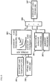
- FIG. 2 is a block diagram illustrating details of calculation for acquiring a scavenging rate.
- the scavenging rate is determined based on the engine rotation speed, a heat generation amount determined by the intake air amount, and a gas amount passing through the exhaust manifold 3.
- an increase in the rotation speed of the turbine 5b delays with respect to an increased speed of the gas amount flowing through the exhaust manifold 3 during a transient operation, which results in a pressure loss.
- the exhaust gas pressure during the transient operation is higher than an exhaust gas pressure during the steady operation with the same intake air amount and the same engine rotation speed.
- transient-exhaust-gas-pressure-variation amount an exhaust gas pressure variation amount
- a collector pressure read module 201 reads the pressure in the intake manifold 2, namely, the detected value obtained by the intake air pressure sensor 19 as a collector pressure.
- An exhaust gas pressure read module 202 reads an exhaust gas pressure acquired by calculation to be described later.
- a transient-exhaust-gas-pressure-variation read module 203 reads a transient-exhaust-gas-pressure-variation amount acquired by calculation to be described later.
- a differential-pressure-before/after-exhaust-valve calculation module 204 subtracts the exhaust gas pressure from the collector pressure, and adds the transient exhaust gas pressure variation thereto, thereby calculating a differential pressure before/after exhaust valve. As a result, the differential pressure before/after exhaust valve containing the transient-exhaust-gas-pressure-variation amount is calculated.
- an engine rotation speed read module 205 reads the engine rotation speed based on a detected value obtained by the crank angle sensor 20, and an overlap amount read module 206 reads a valve overlap amount acquired by calculation to be described later.
- a scavenging rate calculation module 207 acquires the scavenging rate by using a map set in advance based on the engine rotation speed, the valve overlap amount, and the differential pressure before/after exhaust valve, and a scavenging rate setting module 208 reads the calculation result as the scavenging rate.
- the map used on this occasion has a vertical axis representing the differential pressure before/after exhaust valve, and a horizontal axis representing the valve overlap amount, and the control unit 12 stores a plurality of the maps for respective engine rotation speeds.
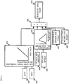
- FIG. 3 is a block diagram illustrating details of calculation for acquiring the exhaust gas pressure read by the exhaust gas pressure read module 202.
- the exhaust gas pressure is greatly influenced by the ambient pressure and the exhaust gas temperature, and hence, by carrying out a correction based thereon, an estimation accuracy of the exhaust gas pressure can be enhanced, and further, the estimation accuracy of the scavenging rate can also be enhanced.
- an exhaust gas pressure sensor does not need to be provided, thereby eliminating an increase in cost for adding the sensor. Specifically, the following calculation is carried out.
- An exhaust gas temperature read module 301 reads the detected value obtained by the exhaust gas temperature sensor 17, and an intake air amount read module 302 reads the detected value obtained by the air flow meter 8.
- a reference exhaust gas pressure calculation module 303 calculates, based on the read values, an exhaust gas pressure serving as a reference by using a map generated in advance. As a result, the exhaust gas pressure based on the intake air amount and the exhaust gas temperature can be used as the reference value.
- a reference ambient pressure read module 304 reads a detected value obtained by the ambient pressure sensor 16 when the reference exhaust gas pressure is calculated. Further, an ambient pressure read module 305 reads a current detected value obtained by the ambient pressure sensor 16. Then, an ambient pressure correction module 306 calculates a sum of a value acquired by subtracting the reference ambient pressure from the reference exhaust gas pressure and the ambient pressure, and an exhaust gas pressure calculation module 307 reads the calculation result as the exhaust gas pressure. As a result, the exhaust gas pressure based on the ambient pressure can be estimated.
- FIG. 4 is a block diagram illustrating details of calculation for calculating the exhaust gas temperature read by the exhaust gas temperature read module 301 of FIG. 3 .
- An ignition timing read module 401 and an optimal ignition timing read module 402 respectively read an ignition timing ADV and an optimal ignition timing MBT. Then, an exhaust-gas-temperature-increase-by-retarding calculation module 403 calculates a retarded amount which is a difference between the optimal ignition timing MBT and the ignition timing ADV, and uses a map generated in advance to calculate an exhaust gas temperature increase amount by retarding which is an increased amount of the exhaust gas temperature caused by an ignition timing retarding.
- an intake air read module 404 and an engine rotation speed read module 405 respectively read the intake air amount and the engine rotation speed
- a reference exhaust gas temperature calculation module 406 searches a map generated in advance for each engine rotation speed by using the intake air amount, thereby calculating a reference exhaust gas temperature.
- the reference exhaust gas temperature is an exhaust gas temperature determined only from the relationship between the intake air amount and the engine rotation speed, without including an influence from the ignition timing retarding, the temperature of the intake air, and the like.
- a reference intake air temperature read module 407 reads a reference intake air temperature which is a temperature of intake air while passing through the air flow meter 8 and a collector intake air read module 408 reads a collector intake air temperature which is a temperature in the intake manifold 2.
- the collector intake air temperature may be detected by providing a temperature sensor, or may be estimated by calculation from the intake air amount, the supercharged pressure, and the like.
- An exhaust gas temperature correction module 409 corrects the reference exhaust gas temperature by using a difference between the reference intake air temperature and the collector intake air temperature, and by further using the exhaust gas temperature increase amount by retarding. Then, the result is stored as the exhaust gas temperature in an exhaust gas temperature setting module 410.
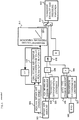
- FIG. 5 is a block diagram for calculating the transient-exhaust-gas-pressure-variation amount read by the transient-exhaust-gas-pressure-variation read module.
- the transient-exhaust-gas-pressure-variation amount is calculated.
- An intake air amount read module 501 reads a detected value obtained by the air flow meter 8.
- a throttle valve opening read module 502 reads the throttle opening.
- the throttle valve opening may be detected by a throttle position sensor, or, for an electronically controlled throttle, an instruction value directed to an actuator for driving the throttle valve may be read.
- An intake air change speed calculation module 503 calculates, based on the intake air amount read by the intake air amount read module 501, an intake air change speed ⁇ QA/ms which is a change speed of the intake air amount per millisecond. Whether the supercharger 5 is in the transient state or the steady state is determined by the change amount of the intake air amount, and, by using the intake air change speed ⁇ QA/ms calculated by using the measured intake air amount, the transient exhaust gas pressure variation can be accurately estimated.
- An intake air change speed correction value calculation module 514 calculates a value obtained by imparting a first order delay to the intake air change speed ⁇ QA/ms by using the following equation (1) as an intake air change speed correction value QMv.
- QMv ⁇ QA / ms ⁇ k + 1 ⁇ k ⁇ QMvz
- a transient-exhaust-gas-pressure-variation amount estimation module 511 calculates, based on the intake air change speed correction value QMv acquired as described above, a transient-exhaust-gas-pressure-variation amount serving as a reference by using a map generated in advance, and inputs the calculation result to a switch module 512.
- An intake-air-amount change amount calculation module 504 calculates a change amount of the intake air amount, and a first determination module 508 compares a first transient determination criterion stored in advance in a first transient determination criterion setting module 505 and the intake-air-amount change amount with each other.
- a throttle-valve-opening change amount calculation module 506 calculates a change amount of the throttle valve opening, and a second determination module 509 compares a second transient determination criterion stored in advance in a second transient determination criterion setting module 507 and the throttle-valve-opening change amount with each other.
- a third determination module 510 reads determination results of the first determination module 508 and the second determination module 509. Then, when at least one of a determination that the intake-air-amount change amount is larger than the first transient determination criterion in the first determination module 508 and a determination that the throttle-valve-opening change amount is larger than the second transient determination criterion in the second determination module 509 is made, the third determination module 510 determines that the operation state is a transient operation state.
- the determination result is input to the switch module 512, and when the operation state is a transient operation state, the switch module 512 switches to a side of adding the transient exhaust gas pressure variation, and when the operation state is not a transient operation state, the switch module 512 switches to a side of not adding the transient-exhaust-gas-pressure-variation amount.
- a transient-exhaust-gas-pressure-variation determination module 513 sets the value output from the switch module 512 as the transient-exhaust-gas-pressure-variation amount.
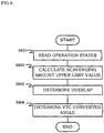
- FIG. 6 is a flowchart illustrating a control routine for determining a converted angle for the valve timing control mechanism 14 carried out by the control unit 12. In the course of the control, the valve overlap period is calculated.
- Step S601 the control unit 12 reads operation states of the internal combustion engine 1 such as the collector pressure, the engine rotation speed, the intake air temperature, the ambient pressure, and a basic injection pulse.
- Step S602 the control unit 12 calculates a scavenging amount upper limit value determined from the operation states. A description is now given of an example of how to acquire the scavenging amount upper limit value.
- FIG. 7 is a block diagram for calculating the scavenging amount upper limit value based on a catalyst temperature.
- the temperature of the exhaust gas catalyst 18 by the combustion can increase more as the scavenging amount increases.
- the exhaust gas catalyst 18 degrades in an exhaust gas purification capability when the temperature excessively increases, and hence the upper limit for the scavenging amount is set to restrain the temperature increase of the exhaust gas catalyst 18.
- the collector pressure Boost the engine rotation speed NE
- a basic injection pulse TP the intake air temperature TAN
- the ambient pressure PAMB the ambient pressure
- a catalyst upper limit temperature calculation module 701 calculates a catalyst upper limit temperature which is an upper limit temperature of the exhaust gas catalyst 18 determined by the operation states.
- a scavenging-less catalyst upper limit temperature calculation module 702 calculates a scavenging-less catalyst estimated temperature which is an estimated temperature of the exhaust gas catalyst 18 in an operation state without the scavenging, namely, an operation state where the mixture of the scavenging gas and the exhaust gas is not combusted.
- a permissible-catalyst-temperature-increase-value-upon-scavenging calculation module 703 calculates a permissible catalyst temperature increase value upon scavenging, which is a difference between the catalyst upper limit temperature and the scavenging-less catalyst estimated temperature.
- An increase in temperature of the exhaust gas catalyst 18 upon the scavenging can be permitted by an amount corresponding to the permissible catalyst temperature increase value upon scavenging.
- a catalyst-temperature-permitting scavenging amount calculation module 705 calculates, based on the permissible catalyst temperature increase value upon scavenging and the air/fuel ratio in the cylinder of the internal combustion engine 1 acquired by a cylinder internal air/fuel ratio calculation module 704, by using a map generated in advance, a catalyst-temperature-permitting scavenging amount which is a scavenging amount upper limit value determined by the temperature of the exhaust gas catalyst 18.
- the map used on this occasion is a map representing a relationship between the scavenging amount and a catalyst temperature increase amount for each cylinder internal air/fuel ratio.
- a catalyst-temperature-permitting scavenging amount determination module 706 sets the calculated result as a catalyst-temperature-permitting scavenging amount.
- Step S603 of FIG. 6 the control unit 12 determines a valve overlap period based on the scavenging amount acquired in Step S602.
- the valve overlap period can be easily set based on the scavenging amount.
- the control unit 12 determines, in order to realize the valve overlap period determined in Step S603, the converted angle of the valve timing control mechanism 14.
- the converted angle can be easily determined based on the valve overlap period.
- the overlap amount read module 206 of FIG. 2 reads this value.
- the scavenging rate to which the influence of the exhaust gas pressure is added is acquired.
- this embodiment provides the following effects.
- the control unit 12 estimates the scavenging amount based on the engine rotation speed, the valve overlap period, the collector pressure, and the exhaust gas pressure, and hence regardless of whether the turbine rotation speed is in the equilibrium state in terms of the gas flow amount or the turbine rotation speed is increasing, the scavenging rate can be accurately estimated.
- the control unit 12 estimates the exhaust gas pressure in the steady operation state based on the operation states of the internal combustion engine 1, thereby estimating the exhaust-gas-pressure-change amount in the transient operation state based on the action state of the supercharger 5. Then, by correcting the estimated exhaust gas pressure value in the steady operation state by the estimated exhaust-gas-pressure-change amount value in the transient operation state, the exhaust gas pressure is estimated.
- the exhaust gas pressure in the steady operation state determined by the operation states such as the engine rotation speed is corrected by the exhaust gas pressure incremental/decremental amount in the transient operation state determined by the action state of the supercharger 5 such as the intake air change speed, and hence the scavenging rate can be highly accurately estimated.
- the control unit 12 uses, as the action state of the supercharger 5, the change speed of the air amount passing through the intake manifold 2. Whether the supercharger 5 is in the equilibrium state or the transient state is determined by the air amount passing through the compressor 5a of the supercharger 5. Therefore, by using the change speed of the air amount passing through the intake manifold 2, which is the above-mentioned air amount itself, the action state of the supercharger 5 can be properly recognized.
- the control unit 12 uses, as parameters for estimating the exhaust gas pressure in the steady state, at least the exhaust gas temperature and the ambient pressure, and hence the control unit 12 can estimate the exhaust gas pressure without using the exhaust gas pressure sensor.
- the control unit 12 estimates the exhaust gas temperature based on the operation states of the internal combustion engine 1, and estimates the exhaust gas pressure in the steady operation state based on the estimated exhaust gas temperature value, and hence the control unit 12 can accurately estimate the exhaust gas temperature determined by the operation states of the internal combustion engine 1.
- the control unit 12 uses an ignition timing retarded amount as one of the parameters representing the operation states in order to estimate the exhaust gas temperature.
- the exhaust gas temperature is determined by the operation states such as the engine rotation speed, even if the engine rotation speed and the like are the same, the exhaust gas temperature also changes when the ignition timing changes.
- the ignition timing is included into the parameters for estimating the exhaust gas temperature, the estimation accuracy of the exhaust gas temperature can be enhanced.
- a system to which this embodiment is applied is the same as that of the first embodiment and the calculation for acquiring the scavenging rate is basically the same as that of FIG. 2 , but how to acquire the transient exhaust air pressure variation read by the transient-exhaust-gas-pressure-variation read module 203 of FIG. 2 is different.
- FIG. 8 is a block diagram illustrating details of calculating the transient exhaust gas pressure variation according to this embodiment. A different point from the calculation of FIG. 5 is how to calculate the intake air change speed ⁇ QA/ms, and hence a description is given of only this point.
- the intake air change speed calculation module 503 calculates the intake air change speed based on the intake air amount, but in FIG. 8 , the intake air change speed is calculated as described below.
- a throttle opening read module 815 reads the opening of the throttle valve 4 determined based on the detected value obtained by the accelerator opening degree sensor 13. Then, an opening area conversion module 817 calculates a throttle opening area corresponding to the opening of the throttle valve 4, namely, an opening area of the intake passage of the throttle valve 4 installed portion. On this occasion, a table which assigns the throttle opening area with the throttle opening as illustrated in FIG. 8 is used.
- the engine rotation speed read module 816 reads the engine rotation speed.
- the intake air amount calculation module 819 calculates an intake air amount per cycle by using the throttle opening area and the engine rotation speed, and further using an intake air conversion coefficient read by an intake air conversion coefficient read module 818.
- the intake air change speed calculation module 820 calculates the intake air change speed ⁇ QA/ms. Specifically, the intake air change speed calculation module 820 calculates a difference between the intake air amount calculated upon the previous calculation, and the intake air amount calculated this time.
- the change speed of the intake air amount may be calculated based on the opening of the throttle valve 4 and the engine rotation speed.
- the control unit 12 uses the change speed of the throttle valve opening area as the action state of the supercharger 5. Whether the supercharger 5 is in the equilibrium state or the transient state is determined by the air amount passing through the compressor 5a of the supercharger 5. Thus, by using the change speed of the throttle valve opening area controlling the air amount, the action state of the supercharger 5 can be properly recognized.
Landscapes
- Engineering & Computer Science (AREA)
- Chemical & Material Sciences (AREA)
- Combustion & Propulsion (AREA)
- Mechanical Engineering (AREA)
- General Engineering & Computer Science (AREA)
- Combined Controls Of Internal Combustion Engines (AREA)
- Output Control And Ontrol Of Special Type Engine (AREA)
- Supercharger (AREA)
Claims (3)
- Dispositif de commande pour un moteur à combustion interne (1) équipé d'un compresseur d'alimentation (5), comprenant :un moyen de détection de quantité d'air d'admission (8) pour détecter une quantité d'air d'admission ;un moyen de détection d'ouverture d'accélérateur (13) pour détecter un degré d'ouverture d'accélérateur ;un moyen de détection de vitesse de rotation de moteur (20) pour détecter une vitesse de rotation de moteur ;un moyen de lecture de pression ambiante (16) pour lire une pression ambiante ;un moyen de lecture de chevauchement (12) pour lire une période de chevauchement de soupape ;un moyen de détection de pression de collecteur (19) pour détecter une pression de collecteur ;un moyen d'estimation de pression de gaz d'échappement (12) pour estimer une pression de gaz d'échappement sur un côté amont du compresseur d'alimentation (5) ; etun moyen d'estimation de quantité de balayage (12) pour estimer une quantité de balayage sur la base de la vitesse de rotation de moteur, de la période de chevauchement de soupape, de la pression de collecteur et de la pression de gaz d'échappement,dans lequel le moyen d'estimation de pression de gaz d'échappement (12) comprend :un module d'estimation de pression de gaz d'échappement stable pour estimer une pression de gaz d'échappement dans un état de fonctionnement stable sur la base d'au moins une température de gaz d'échappement, la quantité d'air d'admission et la pression ambiante ; etun module d'estimation de quantité de variation de pression de gaz d'échappement transitoire pour estimer une quantité de changement de pression de gaz d'échappement dans un état de fonctionnement transitoire sur la base d'au moins la quantité d'air d'admission et le degré d'ouverture d'accélérateur,dans lequel le moyen d'estimation de pression de gaz d'échappement (12) estime la pression de gaz d'échappement en corrigeant une valeur estimée de la pression de gaz d'échappement dans l'état de fonctionnement stable par une valeur estimée de la quantité de changement de pression de gaz d'échappement dans l'état de fonctionnement transitoire, etdans lequel le module d'estimation de quantité de variation de pression de gaz d'échappement transitoire estime la quantité de changement de pression de gaz d'échappement dans l'état de fonctionnement transitoire en considérant une perte de pression du compresseur d'alimentation sur la base d'une vitesse de changement d'une quantité d'air d'admission ou d'une vitesse de changement d'une surface d'ouverture de papillon.
- Dispositif de commande pour un moteur à combustion interne (1) équipé d'un compresseur d'alimentation (5) selon la revendication 1, comprenant en outre :un moyen de détection de température d'air d'admission de collecteur pour détecter une température d'air d'admission de collecteur ;dans lequel le module d'estimation de pression de gaz d'échappement stable estime la température de gaz d'échappement sur la base de la quantité d'air d'admission, du degré d'ouverture d'accélérateur, de la vitesse de rotation de moteur et de la température d'air d'admission de collecteur, et estime la pression de gaz d'échappement dans l'état de fonctionnement stable sur la base d'une valeur estimée de la température de gaz d'échappement.
- Dispositif de commande pour un moteur à combustion interne (1) équipé d'un compresseur d'alimentation (5) selon la revendication 2, comprenant en outre :un moyen de lecture de quantité retardée de calage d'allumage pour lire une quantité retardée de calage d'allumage ;dans lequel le module d'estimation de pression de gaz d'échappement stable utilise la quantité retardée de calage d'allumage comme l'un des paramètres pour estimer la température de gaz d'échappement.
Applications Claiming Priority (2)
| Application Number | Priority Date | Filing Date | Title |
|---|---|---|---|
| JP2011024144A JP5786348B2 (ja) | 2011-02-07 | 2011-02-07 | 過給機付き内燃機関の制御装置 |
| PCT/JP2012/052023 WO2012108287A1 (fr) | 2011-02-07 | 2012-01-30 | Dispositif de commande pour moteur à combustion interne équipé d'un compresseur volumétrique |
Publications (3)
| Publication Number | Publication Date |
|---|---|
| EP2674589A1 EP2674589A1 (fr) | 2013-12-18 |
| EP2674589A4 EP2674589A4 (fr) | 2016-12-21 |
| EP2674589B1 true EP2674589B1 (fr) | 2018-03-14 |
Family
ID=46638503
Family Applications (1)
| Application Number | Title | Priority Date | Filing Date |
|---|---|---|---|
| EP12744951.0A Not-in-force EP2674589B1 (fr) | 2011-02-07 | 2012-01-30 | Dispositif de commande pour moteur à combustion interne équipé d'un compresseur volumétrique |
Country Status (6)
| Country | Link |
|---|---|
| US (1) | US9002625B2 (fr) |
| EP (1) | EP2674589B1 (fr) |
| JP (1) | JP5786348B2 (fr) |
| KR (1) | KR101448415B1 (fr) |
| CN (1) | CN103384759B (fr) |
| WO (1) | WO2012108287A1 (fr) |
Families Citing this family (8)
| Publication number | Priority date | Publication date | Assignee | Title |
|---|---|---|---|---|
| WO2012108362A1 (fr) * | 2011-02-07 | 2012-08-16 | 日産自動車株式会社 | Dispositif de commande pour moteur à combustion interne multicylindres |
| US9476365B2 (en) * | 2012-05-17 | 2016-10-25 | Ford Global Technologies, Llc | Coordination of cam timing and blow-through air delivery |
| DE102014214438B3 (de) * | 2014-07-23 | 2015-08-13 | Continental Automotive Gmbh | Verfahren zur Steuerung der Kraftstoffzufuhr zur Einstellung eines gewünschten Luft-Kraftstoff-Verhältnisses in einem Zylinder eines Verbrennungsmotors |
| US9657670B2 (en) * | 2015-10-02 | 2017-05-23 | GM Global Technology Operations LLC | Exhaust system temperature estimation systems and methods |
| US10683817B2 (en) * | 2016-12-16 | 2020-06-16 | Ford Global Technologies, Llc | Systems and methods for a split exhaust engine system |
| JP6825931B2 (ja) * | 2017-02-15 | 2021-02-03 | 三菱重工業株式会社 | 可変型ターボチャージャ装置 |
| CN108798917B (zh) * | 2017-04-28 | 2021-12-10 | 长城汽车股份有限公司 | 一种发动机扫气控制方法及装置 |
| US10221794B1 (en) * | 2017-11-07 | 2019-03-05 | Fca Us Llc | Measurement, modeling, and estimation of scavenging airflow in an internal combustion engine |
Family Cites Families (15)
| Publication number | Priority date | Publication date | Assignee | Title |
|---|---|---|---|---|
| JP3161288B2 (ja) | 1995-06-23 | 2001-04-25 | 三菱自動車工業株式会社 | ターボ過給機付エンジンの排気圧力検出装置および空気過剰率検出装置 |
| DE19723210B4 (de) * | 1996-06-03 | 2005-04-28 | Nissan Motor | Steuervorrichtung für eine Brennkraftmaschine mit Abgasrückführung |
| GB2313927B (en) * | 1996-06-03 | 1999-06-23 | Nissan Motor | EGR control apparatus for internal combustion engine |
| JP3395782B2 (ja) * | 2002-04-26 | 2003-04-14 | 日産自動車株式会社 | 内燃機関の吸気系圧力推定装置 |
| JP4232636B2 (ja) | 2004-01-13 | 2009-03-04 | トヨタ自動車株式会社 | 内燃機関の制御装置 |
| US7610757B2 (en) * | 2004-07-30 | 2009-11-03 | Komatsu Ltd. | Intake controller of internal combustion engine |
| JP2006132351A (ja) * | 2004-11-02 | 2006-05-25 | Toyota Motor Corp | 内燃機関の制御装置および排気温度推定装置 |
| JP2006299992A (ja) * | 2005-04-22 | 2006-11-02 | Toyota Motor Corp | 内燃機関の制御システム |
| US7281529B2 (en) * | 2005-10-17 | 2007-10-16 | International Engine Intellectual Property Company, Llc | EGR cooler purging apparatus and method |
| DE102006041518A1 (de) * | 2006-09-05 | 2008-03-06 | Ford Global Technologies, LLC, Dearborn | Verfahren zur Bestimmung eines Abgasdrucks einer Brennkraftmaschine und Brennkraftmaschine mit Abgasdruckbestimmung |
| JP4253339B2 (ja) * | 2006-09-21 | 2009-04-08 | 株式会社日立製作所 | 内燃機関の制御装置 |
| JP4877200B2 (ja) * | 2007-11-06 | 2012-02-15 | トヨタ自動車株式会社 | 内燃機関の制御装置 |
| WO2010092678A1 (fr) * | 2009-02-13 | 2010-08-19 | トヨタ自動車株式会社 | Dispositif de commande de moteur à combustion interne |
| JP4952848B2 (ja) * | 2010-02-26 | 2012-06-13 | トヨタ自動車株式会社 | 内燃機関の制御装置 |
| US9103293B2 (en) * | 2011-12-15 | 2015-08-11 | Ford Global Technologies, Llc | Method for reducing sensitivity for engine scavenging |
-
2011
- 2011-02-07 JP JP2011024144A patent/JP5786348B2/ja not_active Expired - Fee Related
-
2012
- 2012-01-30 KR KR1020137021218A patent/KR101448415B1/ko not_active Expired - Fee Related
- 2012-01-30 WO PCT/JP2012/052023 patent/WO2012108287A1/fr not_active Ceased
- 2012-01-30 CN CN201280007971.8A patent/CN103384759B/zh not_active Expired - Fee Related
- 2012-01-30 EP EP12744951.0A patent/EP2674589B1/fr not_active Not-in-force
- 2012-01-30 US US13/983,903 patent/US9002625B2/en not_active Expired - Fee Related
Also Published As
| Publication number | Publication date |
|---|---|
| EP2674589A4 (fr) | 2016-12-21 |
| JP5786348B2 (ja) | 2015-09-30 |
| US9002625B2 (en) | 2015-04-07 |
| WO2012108287A1 (fr) | 2012-08-16 |
| KR101448415B1 (ko) | 2014-10-07 |
| CN103384759A (zh) | 2013-11-06 |
| EP2674589A1 (fr) | 2013-12-18 |
| CN103384759B (zh) | 2016-01-13 |
| JP2012163048A (ja) | 2012-08-30 |
| US20130312714A1 (en) | 2013-11-28 |
| KR20130113518A (ko) | 2013-10-15 |
Similar Documents
| Publication | Publication Date | Title |
|---|---|---|
| EP2674602B1 (fr) | Dispositif de commande pour moteur à combustion interne multicylindres | |
| EP2674589B1 (fr) | Dispositif de commande pour moteur à combustion interne équipé d'un compresseur volumétrique | |
| US9890718B2 (en) | Control apparatus for internal combustion engine | |
| EP2674595B1 (fr) | Dispositif de commande pour moteur à combustion interne équipé de turbocompresseur | |
| US8326516B2 (en) | Engine control device | |
| EP2787203A1 (fr) | Dispositif de commande pour moteur à combustion interne | |
| EP2444641A2 (fr) | Dispositif de commande pour moteur à essence avec injection directe | |
| JP2005307847A (ja) | 内燃機関の空気量算出装置 | |
| JP2012172653A (ja) | 内燃機関の制御装置 | |
| US20130245916A1 (en) | Engine Control Unit and Atmospheric Pressure Estimation Method | |
| US8938960B2 (en) | Control apparatus for internal combustion engine | |
| EP2570644A1 (fr) | Dispositif de commande pour moteur à combustion interne | |
| EP2584178B1 (fr) | Dispositif de commande pour moteur à combustion interne | |
| JP4956473B2 (ja) | 燃料噴射制御装置 | |
| JP2016028204A (ja) | ターボ式過給機付き内燃機関の制御装置 | |
| JP5857678B2 (ja) | 内燃機関の制御装置及び内燃機関の制御方法 | |
| JP2014020252A (ja) | 内燃機関の制御装置 |
Legal Events
| Date | Code | Title | Description |
|---|---|---|---|
| PUAI | Public reference made under article 153(3) epc to a published international application that has entered the european phase |
Free format text: ORIGINAL CODE: 0009012 |
|
| 17P | Request for examination filed |
Effective date: 20130705 |
|
| AK | Designated contracting states |
Kind code of ref document: A1 Designated state(s): AL AT BE BG CH CY CZ DE DK EE ES FI FR GB GR HR HU IE IS IT LI LT LU LV MC MK MT NL NO PL PT RO RS SE SI SK SM TR |
|
| DAX | Request for extension of the european patent (deleted) | ||
| RA4 | Supplementary search report drawn up and despatched (corrected) |
Effective date: 20161118 |
|
| RIC1 | Information provided on ipc code assigned before grant |
Ipc: F02D 45/00 20060101ALI20161114BHEP Ipc: F02B 39/16 20060101AFI20161114BHEP Ipc: F02B 37/00 20060101ALI20161114BHEP Ipc: F02D 23/00 20060101ALI20161114BHEP |
|
| GRAP | Despatch of communication of intention to grant a patent |
Free format text: ORIGINAL CODE: EPIDOSNIGR1 |
|
| STAA | Information on the status of an ep patent application or granted ep patent |
Free format text: STATUS: GRANT OF PATENT IS INTENDED |
|
| INTG | Intention to grant announced |
Effective date: 20171109 |
|
| GRAS | Grant fee paid |
Free format text: ORIGINAL CODE: EPIDOSNIGR3 |
|
| GRAA | (expected) grant |
Free format text: ORIGINAL CODE: 0009210 |
|
| STAA | Information on the status of an ep patent application or granted ep patent |
Free format text: STATUS: THE PATENT HAS BEEN GRANTED |
|
| RIN1 | Information on inventor provided before grant (corrected) |
Inventor name: TAKAKI, DAISUKE Inventor name: TSUYUKI, TAKESHI Inventor name: KATOU, NAOZUMI |
|
| AK | Designated contracting states |
Kind code of ref document: B1 Designated state(s): AL AT BE BG CH CY CZ DE DK EE ES FI FR GB GR HR HU IE IS IT LI LT LU LV MC MK MT NL NO PL PT RO RS SE SI SK SM TR |
|
| REG | Reference to a national code |
Ref country code: GB Ref legal event code: FG4D |
|
| REG | Reference to a national code |
Ref country code: AT Ref legal event code: REF Ref document number: 979116 Country of ref document: AT Kind code of ref document: T Effective date: 20180315 Ref country code: CH Ref legal event code: EP |
|
| REG | Reference to a national code |
Ref country code: IE Ref legal event code: FG4D |
|
| REG | Reference to a national code |
Ref country code: DE Ref legal event code: R096 Ref document number: 602012043982 Country of ref document: DE |
|
| REG | Reference to a national code |
Ref country code: NL Ref legal event code: MP Effective date: 20180314 |
|
| REG | Reference to a national code |
Ref country code: LT Ref legal event code: MG4D |
|
| PG25 | Lapsed in a contracting state [announced via postgrant information from national office to epo] |
Ref country code: LT Free format text: LAPSE BECAUSE OF FAILURE TO SUBMIT A TRANSLATION OF THE DESCRIPTION OR TO PAY THE FEE WITHIN THE PRESCRIBED TIME-LIMIT Effective date: 20180314 Ref country code: CY Free format text: LAPSE BECAUSE OF FAILURE TO SUBMIT A TRANSLATION OF THE DESCRIPTION OR TO PAY THE FEE WITHIN THE PRESCRIBED TIME-LIMIT Effective date: 20180314 Ref country code: ES Free format text: LAPSE BECAUSE OF FAILURE TO SUBMIT A TRANSLATION OF THE DESCRIPTION OR TO PAY THE FEE WITHIN THE PRESCRIBED TIME-LIMIT Effective date: 20180314 Ref country code: NO Free format text: LAPSE BECAUSE OF FAILURE TO SUBMIT A TRANSLATION OF THE DESCRIPTION OR TO PAY THE FEE WITHIN THE PRESCRIBED TIME-LIMIT Effective date: 20180614 Ref country code: HR Free format text: LAPSE BECAUSE OF FAILURE TO SUBMIT A TRANSLATION OF THE DESCRIPTION OR TO PAY THE FEE WITHIN THE PRESCRIBED TIME-LIMIT Effective date: 20180314 Ref country code: FI Free format text: LAPSE BECAUSE OF FAILURE TO SUBMIT A TRANSLATION OF THE DESCRIPTION OR TO PAY THE FEE WITHIN THE PRESCRIBED TIME-LIMIT Effective date: 20180314 |
|
| REG | Reference to a national code |
Ref country code: AT Ref legal event code: MK05 Ref document number: 979116 Country of ref document: AT Kind code of ref document: T Effective date: 20180314 |
|
| PG25 | Lapsed in a contracting state [announced via postgrant information from national office to epo] |
Ref country code: LV Free format text: LAPSE BECAUSE OF FAILURE TO SUBMIT A TRANSLATION OF THE DESCRIPTION OR TO PAY THE FEE WITHIN THE PRESCRIBED TIME-LIMIT Effective date: 20180314 Ref country code: SE Free format text: LAPSE BECAUSE OF FAILURE TO SUBMIT A TRANSLATION OF THE DESCRIPTION OR TO PAY THE FEE WITHIN THE PRESCRIBED TIME-LIMIT Effective date: 20180314 Ref country code: RS Free format text: LAPSE BECAUSE OF FAILURE TO SUBMIT A TRANSLATION OF THE DESCRIPTION OR TO PAY THE FEE WITHIN THE PRESCRIBED TIME-LIMIT Effective date: 20180314 Ref country code: BG Free format text: LAPSE BECAUSE OF FAILURE TO SUBMIT A TRANSLATION OF THE DESCRIPTION OR TO PAY THE FEE WITHIN THE PRESCRIBED TIME-LIMIT Effective date: 20180614 Ref country code: GR Free format text: LAPSE BECAUSE OF FAILURE TO SUBMIT A TRANSLATION OF THE DESCRIPTION OR TO PAY THE FEE WITHIN THE PRESCRIBED TIME-LIMIT Effective date: 20180615 |
|
| PG25 | Lapsed in a contracting state [announced via postgrant information from national office to epo] |
Ref country code: PL Free format text: LAPSE BECAUSE OF FAILURE TO SUBMIT A TRANSLATION OF THE DESCRIPTION OR TO PAY THE FEE WITHIN THE PRESCRIBED TIME-LIMIT Effective date: 20180314 Ref country code: RO Free format text: LAPSE BECAUSE OF FAILURE TO SUBMIT A TRANSLATION OF THE DESCRIPTION OR TO PAY THE FEE WITHIN THE PRESCRIBED TIME-LIMIT Effective date: 20180314 Ref country code: AL Free format text: LAPSE BECAUSE OF FAILURE TO SUBMIT A TRANSLATION OF THE DESCRIPTION OR TO PAY THE FEE WITHIN THE PRESCRIBED TIME-LIMIT Effective date: 20180314 Ref country code: EE Free format text: LAPSE BECAUSE OF FAILURE TO SUBMIT A TRANSLATION OF THE DESCRIPTION OR TO PAY THE FEE WITHIN THE PRESCRIBED TIME-LIMIT Effective date: 20180314 Ref country code: NL Free format text: LAPSE BECAUSE OF FAILURE TO SUBMIT A TRANSLATION OF THE DESCRIPTION OR TO PAY THE FEE WITHIN THE PRESCRIBED TIME-LIMIT Effective date: 20180314 |
|
| PG25 | Lapsed in a contracting state [announced via postgrant information from national office to epo] |
Ref country code: SM Free format text: LAPSE BECAUSE OF FAILURE TO SUBMIT A TRANSLATION OF THE DESCRIPTION OR TO PAY THE FEE WITHIN THE PRESCRIBED TIME-LIMIT Effective date: 20180314 Ref country code: AT Free format text: LAPSE BECAUSE OF FAILURE TO SUBMIT A TRANSLATION OF THE DESCRIPTION OR TO PAY THE FEE WITHIN THE PRESCRIBED TIME-LIMIT Effective date: 20180314 Ref country code: SK Free format text: LAPSE BECAUSE OF FAILURE TO SUBMIT A TRANSLATION OF THE DESCRIPTION OR TO PAY THE FEE WITHIN THE PRESCRIBED TIME-LIMIT Effective date: 20180314 Ref country code: CZ Free format text: LAPSE BECAUSE OF FAILURE TO SUBMIT A TRANSLATION OF THE DESCRIPTION OR TO PAY THE FEE WITHIN THE PRESCRIBED TIME-LIMIT Effective date: 20180314 |
|
| REG | Reference to a national code |
Ref country code: DE Ref legal event code: R097 Ref document number: 602012043982 Country of ref document: DE |
|
| PG25 | Lapsed in a contracting state [announced via postgrant information from national office to epo] |
Ref country code: PT Free format text: LAPSE BECAUSE OF FAILURE TO SUBMIT A TRANSLATION OF THE DESCRIPTION OR TO PAY THE FEE WITHIN THE PRESCRIBED TIME-LIMIT Effective date: 20180716 |
|
| PLBE | No opposition filed within time limit |
Free format text: ORIGINAL CODE: 0009261 |
|
| STAA | Information on the status of an ep patent application or granted ep patent |
Free format text: STATUS: NO OPPOSITION FILED WITHIN TIME LIMIT |
|
| PG25 | Lapsed in a contracting state [announced via postgrant information from national office to epo] |
Ref country code: DK Free format text: LAPSE BECAUSE OF FAILURE TO SUBMIT A TRANSLATION OF THE DESCRIPTION OR TO PAY THE FEE WITHIN THE PRESCRIBED TIME-LIMIT Effective date: 20180314 |
|
| 26N | No opposition filed |
Effective date: 20181217 |
|
| PG25 | Lapsed in a contracting state [announced via postgrant information from national office to epo] |
Ref country code: IT Free format text: LAPSE BECAUSE OF FAILURE TO SUBMIT A TRANSLATION OF THE DESCRIPTION OR TO PAY THE FEE WITHIN THE PRESCRIBED TIME-LIMIT Effective date: 20180314 Ref country code: SI Free format text: LAPSE BECAUSE OF FAILURE TO SUBMIT A TRANSLATION OF THE DESCRIPTION OR TO PAY THE FEE WITHIN THE PRESCRIBED TIME-LIMIT Effective date: 20180314 |
|
| PG25 | Lapsed in a contracting state [announced via postgrant information from national office to epo] |
Ref country code: MC Free format text: LAPSE BECAUSE OF FAILURE TO SUBMIT A TRANSLATION OF THE DESCRIPTION OR TO PAY THE FEE WITHIN THE PRESCRIBED TIME-LIMIT Effective date: 20180314 |
|
| REG | Reference to a national code |
Ref country code: CH Ref legal event code: PL |
|
| PG25 | Lapsed in a contracting state [announced via postgrant information from national office to epo] |
Ref country code: LU Free format text: LAPSE BECAUSE OF NON-PAYMENT OF DUE FEES Effective date: 20190130 |
|
| REG | Reference to a national code |
Ref country code: BE Ref legal event code: MM Effective date: 20190131 |
|
| REG | Reference to a national code |
Ref country code: IE Ref legal event code: MM4A |
|
| PG25 | Lapsed in a contracting state [announced via postgrant information from national office to epo] |
Ref country code: BE Free format text: LAPSE BECAUSE OF NON-PAYMENT OF DUE FEES Effective date: 20190131 |
|
| PG25 | Lapsed in a contracting state [announced via postgrant information from national office to epo] |
Ref country code: CH Free format text: LAPSE BECAUSE OF NON-PAYMENT OF DUE FEES Effective date: 20190131 Ref country code: LI Free format text: LAPSE BECAUSE OF NON-PAYMENT OF DUE FEES Effective date: 20190131 |
|
| PG25 | Lapsed in a contracting state [announced via postgrant information from national office to epo] |
Ref country code: IE Free format text: LAPSE BECAUSE OF NON-PAYMENT OF DUE FEES Effective date: 20190130 |
|
| PGFP | Annual fee paid to national office [announced via postgrant information from national office to epo] |
Ref country code: FR Payment date: 20191216 Year of fee payment: 9 |
|
| PG25 | Lapsed in a contracting state [announced via postgrant information from national office to epo] |
Ref country code: TR Free format text: LAPSE BECAUSE OF FAILURE TO SUBMIT A TRANSLATION OF THE DESCRIPTION OR TO PAY THE FEE WITHIN THE PRESCRIBED TIME-LIMIT Effective date: 20180314 |
|
| PGFP | Annual fee paid to national office [announced via postgrant information from national office to epo] |
Ref country code: DE Payment date: 20200114 Year of fee payment: 9 Ref country code: GB Payment date: 20200122 Year of fee payment: 9 |
|
| PG25 | Lapsed in a contracting state [announced via postgrant information from national office to epo] |
Ref country code: MT Free format text: LAPSE BECAUSE OF NON-PAYMENT OF DUE FEES Effective date: 20190130 |
|
| PG25 | Lapsed in a contracting state [announced via postgrant information from national office to epo] |
Ref country code: IS Free format text: LAPSE BECAUSE OF FAILURE TO SUBMIT A TRANSLATION OF THE DESCRIPTION OR TO PAY THE FEE WITHIN THE PRESCRIBED TIME-LIMIT Effective date: 20180714 |
|
| PG25 | Lapsed in a contracting state [announced via postgrant information from national office to epo] |
Ref country code: HU Free format text: LAPSE BECAUSE OF FAILURE TO SUBMIT A TRANSLATION OF THE DESCRIPTION OR TO PAY THE FEE WITHIN THE PRESCRIBED TIME-LIMIT; INVALID AB INITIO Effective date: 20120130 |
|
| REG | Reference to a national code |
Ref country code: DE Ref legal event code: R119 Ref document number: 602012043982 Country of ref document: DE |
|
| GBPC | Gb: european patent ceased through non-payment of renewal fee |
Effective date: 20210130 |
|
| PG25 | Lapsed in a contracting state [announced via postgrant information from national office to epo] |
Ref country code: FR Free format text: LAPSE BECAUSE OF NON-PAYMENT OF DUE FEES Effective date: 20210131 |
|
| PG25 | Lapsed in a contracting state [announced via postgrant information from national office to epo] |
Ref country code: DE Free format text: LAPSE BECAUSE OF NON-PAYMENT OF DUE FEES Effective date: 20210803 Ref country code: GB Free format text: LAPSE BECAUSE OF NON-PAYMENT OF DUE FEES Effective date: 20210130 |
|
| PG25 | Lapsed in a contracting state [announced via postgrant information from national office to epo] |
Ref country code: MK Free format text: LAPSE BECAUSE OF FAILURE TO SUBMIT A TRANSLATION OF THE DESCRIPTION OR TO PAY THE FEE WITHIN THE PRESCRIBED TIME-LIMIT Effective date: 20180314 |