EP2674664B1 - Lampe pour un véhicule automobile - Google Patents
Lampe pour un véhicule automobile Download PDFInfo
- Publication number
- EP2674664B1 EP2674664B1 EP13171213.5A EP13171213A EP2674664B1 EP 2674664 B1 EP2674664 B1 EP 2674664B1 EP 13171213 A EP13171213 A EP 13171213A EP 2674664 B1 EP2674664 B1 EP 2674664B1
- Authority
- EP
- European Patent Office
- Prior art keywords
- lamp fixture
- circuit board
- reflector
- front cover
- vehicle
- Prior art date
- Legal status (The legal status is an assumption and is not a legal conclusion. Google has not performed a legal analysis and makes no representation as to the accuracy of the status listed.)
- Not-in-force
Links
Images


Classifications
-
- F—MECHANICAL ENGINEERING; LIGHTING; HEATING; WEAPONS; BLASTING
- F21—LIGHTING
- F21S—NON-PORTABLE LIGHTING DEVICES; SYSTEMS THEREOF; VEHICLE LIGHTING DEVICES SPECIALLY ADAPTED FOR VEHICLE EXTERIORS
- F21S41/00—Illuminating devices specially adapted for vehicle exteriors, e.g. headlamps
- F21S41/10—Illuminating devices specially adapted for vehicle exteriors, e.g. headlamps characterised by the light source
- F21S41/14—Illuminating devices specially adapted for vehicle exteriors, e.g. headlamps characterised by the light source characterised by the type of light source
- F21S41/141—Light emitting diodes [LED]
- F21S41/147—Light emitting diodes [LED] the main emission direction of the LED being angled to the optical axis of the illuminating device
-
- F—MECHANICAL ENGINEERING; LIGHTING; HEATING; WEAPONS; BLASTING
- F21—LIGHTING
- F21S—NON-PORTABLE LIGHTING DEVICES; SYSTEMS THEREOF; VEHICLE LIGHTING DEVICES SPECIALLY ADAPTED FOR VEHICLE EXTERIORS
- F21S41/00—Illuminating devices specially adapted for vehicle exteriors, e.g. headlamps
-
- F—MECHANICAL ENGINEERING; LIGHTING; HEATING; WEAPONS; BLASTING
- F21—LIGHTING
- F21S—NON-PORTABLE LIGHTING DEVICES; SYSTEMS THEREOF; VEHICLE LIGHTING DEVICES SPECIALLY ADAPTED FOR VEHICLE EXTERIORS
- F21S41/00—Illuminating devices specially adapted for vehicle exteriors, e.g. headlamps
- F21S41/10—Illuminating devices specially adapted for vehicle exteriors, e.g. headlamps characterised by the light source
- F21S41/19—Attachment of light sources or lamp holders
-
- F—MECHANICAL ENGINEERING; LIGHTING; HEATING; WEAPONS; BLASTING
- F21—LIGHTING
- F21S—NON-PORTABLE LIGHTING DEVICES; SYSTEMS THEREOF; VEHICLE LIGHTING DEVICES SPECIALLY ADAPTED FOR VEHICLE EXTERIORS
- F21S41/00—Illuminating devices specially adapted for vehicle exteriors, e.g. headlamps
- F21S41/20—Illuminating devices specially adapted for vehicle exteriors, e.g. headlamps characterised by refractors, transparent cover plates, light guides or filters
- F21S41/28—Cover glass
-
- F—MECHANICAL ENGINEERING; LIGHTING; HEATING; WEAPONS; BLASTING
- F21—LIGHTING
- F21S—NON-PORTABLE LIGHTING DEVICES; SYSTEMS THEREOF; VEHICLE LIGHTING DEVICES SPECIALLY ADAPTED FOR VEHICLE EXTERIORS
- F21S41/00—Illuminating devices specially adapted for vehicle exteriors, e.g. headlamps
- F21S41/30—Illuminating devices specially adapted for vehicle exteriors, e.g. headlamps characterised by reflectors
- F21S41/39—Attachment thereof
-
- F—MECHANICAL ENGINEERING; LIGHTING; HEATING; WEAPONS; BLASTING
- F21—LIGHTING
- F21S—NON-PORTABLE LIGHTING DEVICES; SYSTEMS THEREOF; VEHICLE LIGHTING DEVICES SPECIALLY ADAPTED FOR VEHICLE EXTERIORS
- F21S43/00—Signalling devices specially adapted for vehicle exteriors, e.g. brake lamps, direction indicator lights or reversing lights
- F21S43/10—Signalling devices specially adapted for vehicle exteriors, e.g. brake lamps, direction indicator lights or reversing lights characterised by the light source
- F21S43/13—Signalling devices specially adapted for vehicle exteriors, e.g. brake lamps, direction indicator lights or reversing lights characterised by the light source characterised by the type of light source
- F21S43/14—Light emitting diodes [LED]
-
- F—MECHANICAL ENGINEERING; LIGHTING; HEATING; WEAPONS; BLASTING
- F21—LIGHTING
- F21S—NON-PORTABLE LIGHTING DEVICES; SYSTEMS THEREOF; VEHICLE LIGHTING DEVICES SPECIALLY ADAPTED FOR VEHICLE EXTERIORS
- F21S43/00—Signalling devices specially adapted for vehicle exteriors, e.g. brake lamps, direction indicator lights or reversing lights
- F21S43/30—Signalling devices specially adapted for vehicle exteriors, e.g. brake lamps, direction indicator lights or reversing lights characterised by reflectors
- F21S43/37—Attachment thereof
-
- F—MECHANICAL ENGINEERING; LIGHTING; HEATING; WEAPONS; BLASTING
- F21—LIGHTING
- F21S—NON-PORTABLE LIGHTING DEVICES; SYSTEMS THEREOF; VEHICLE LIGHTING DEVICES SPECIALLY ADAPTED FOR VEHICLE EXTERIORS
- F21S45/00—Arrangements within vehicle lighting devices specially adapted for vehicle exteriors, for purposes other than emission or distribution of light
- F21S45/40—Cooling of lighting devices
- F21S45/47—Passive cooling, e.g. using fins, thermal conductive elements or openings
- F21S45/48—Passive cooling, e.g. using fins, thermal conductive elements or openings with means for conducting heat from the inside to the outside of the lighting devices, e.g. with fins on the outer surface of the lighting device
-
- F—MECHANICAL ENGINEERING; LIGHTING; HEATING; WEAPONS; BLASTING
- F21—LIGHTING
- F21S—NON-PORTABLE LIGHTING DEVICES; SYSTEMS THEREOF; VEHICLE LIGHTING DEVICES SPECIALLY ADAPTED FOR VEHICLE EXTERIORS
- F21S45/00—Arrangements within vehicle lighting devices specially adapted for vehicle exteriors, for purposes other than emission or distribution of light
- F21S45/40—Cooling of lighting devices
- F21S45/49—Attachment of the cooling means
Definitions
- the invention relates to a transportation device lamp fixture, and more particularly, to a transportation device lamp fixture that uses a semiconductor light-emitting device.
- a personal mobility vehicle is designed to be a mode of transportation that is between walking and existing vehicles, and is proposed as a vehicle that differs from existing vehicles, based on the concept of reducing the amount of energy consumed for personal transportation.
- a personal mobility vehicle is small compared to an existing vehicle, so the position in which a lamp fixture is able to be mounted is limited. Therefore, a lamp fixture having a simpler structure than an existing vehicle lamp structure is required.
- Document JP 2005-063754 A discloses a head lamp provided with a concave mirror and a surface light source comprising a plurality of LEDs disposed outside the optical axis of the concave mirror.
- the invention provides a transportation device lamp fixture having a simplified structure.
- One aspect of the invention relates to a transportation device lamp fixture that includes a semiconductor light-emitting device, a circuit board to which the semiconductor light-emitting device is mounted, a lamp body, and a front cover that covers an opening of the lamp body.
- the semiconductor light-emitting device and the circuit board are housed inside of a lamp chamber formed by the lamp body and the front cover.
- the circuit board is attached to an inside surface of an upper portion of the front cover.
- the circuit board is provided on the inside surface of the upper portion of the front cover, which obviates the need to provide a separate member for supporting the circuit board.
- the structure of the lamp fixture is able to be simplified.
- the transportation device lamp fixture according to the aspect described above may also include a reflector that reflects light emitted from the semiconductor light-emitting device in front of the lamp fixture.
- the reflector may be attached to the front cover.
- the reflector may include a reflective portion for reflecting the light from the semiconductor light-emitting device, and an attaching portion for attaching the reflector to the front cover.
- the circuit board may be attached to the front cover or the lamp body via the attaching portion of the reflector.
- a heat sink may be formed on a portion of the upper portion of the front cover, and the circuit board may be attached to the heat sink.
- the transportation device lamp fixture described above may be mounted to a transportation device that does not have another heat source that is different from the transportation device lamp fixture, and that is located around a predetermined position where the lamp fixture is attached.
- a transportation device lamp fixture having a simplified structure is able to be provided.
- FIG. 1 is a front view of a transportation device lamp fixture 10 according to one example embodiment of the invention.
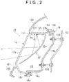
- FIG. 2 is a sectional view (a vertical sectional view) taken along line X - X of the transportation device lamp fixture 10 shown in FIG. 1 .
- the transportation device lamp fixture 10 shown in FIGS. 1 and 2 is a headlamp provided at the front of a transportation device such as a personal mobility vehicle, for example. Therefore, in the example embodiments below, the term “vehicle” will be used instead of the term “transportation device” for simplicity.
- the vehicle lamp fixture 10 includes a lamp body 14 that has a recessed portion that is open toward the front of the lamp fixture, and a transparent front cover 12 that covers the open portion of the lamp body 14.
- the lamp body 14 and the front cover 12 together form a lamp chamber 16.
- the front cover 12 is a member having a sectional recessed shape that is formed by injection molding transparent resin such as acrylic or polycarbonate, and mainly includes a front portion 12a that faces forward of the vehicle, an upper portion 12b that extends horizontally rearward from an upper end portion of the front portion 12a, a bottom portion 12c that extends rearward from a lower end portion of the front portion 12a, a left side portion 12d that extends rearward from a left end portion of the front portion 12a, and a right side portion 12e that extends rearward from a right end portion of the front portion 12a.
- the front portion 12a or only a portion of the front portion 12a of the front cover 12 is exposed on the outside of the vehicle. That is, the front portion 12a or only a portion thereof is exposed to the outside through a hole 101 provided in a hood member 100 that is positioned at the front of the vehicle.
- the upper portion 12b and the bottom portion 12c are covered by the hood member 100, so the upper portion 12b, the bottom portion 12c, the left side portion 12d, and the right side portion 12e are not easily visually recognizable from the outside.
- the hood member 100 may be a front cowl, a bumper, or a bonnet (hood) or the like of the vehicle.
- the lamp body 14 is formed in a container shape that is open at the front.
- the lamp body 14 mainly includes a back portion 14a that faces the front portion 12a of the front cover 12, an upper portion 14b that extends forward from an upper end portion of the back portion 14a, a bottom portion 14c that extends forward from a lower end portion of the back portion 14a, a left side portion, not shown, that extends forward from a right end portion of the back portion 14a, and a right side portion, also not shown, that extends forward from a right end portion of the back portion 14a.
- the lamp body 14 may be formed using polypropylene resin, for example.
- a joining portion 14d for joining and fixing the front cover 12 to the lamp body 14 is provided on tip end portions of ⁇ the upper portion 14b, the bottom portion 14c, the left side portion, and the right side portion of the lamp body 14.
- the vehicle lamp fixture 10 is supported on the vehicle via a first aiming screw 103 and a second aiming screw 104.
- One end portion of the first aiming screw 103 and the second aiming screw 104 is attached to the back portion 14a of the lamp body 14, and the other end portion of the first aiming screw 103 and the second aiming screw 104 is attached to a lamp supporting portion 102 of the vehicle.
- the posture of the vehicle lamp fixture 10 is able to be changed by turning the first aiming screw 103 and the second aiming screw 104, which enables the aim of the vehicle lamp fixture 10 to be adjusted when the vehicle is shipped or inspected, for example.
- Each lamp fixture unit 11 includes an LED 18, a circuit board 20 to which the LED is mounted and that supplies power to the LED 18, and a reflector 22 that reflects light emitted from the LED 18 in front of the lamp fixture.
- the circuit board 20 to which the LED 18 is mounted is directly mounted onto an inside surface 12f of the upper portion 12b of the front cover 12.
- the circuit board 20 is arranged such that a light-emitting surface of the LED 18 faces vertically downward.
- the LED 18 that is mounted on the circuit board 20 may be a white LED with a wattage of approximately 1 W, for example. Also, a plurality of LEDs 18 may be mounted on the circuit board 20.
- the method by which the circuit board 20 is fixed to the upper portion 12b is not particularly limited. That is, the circuit board 20 may be fastened by a screw or fixed by adhesive or the like. Alternatively, a pin may be provided on the inside surface 12f of the upper portion 12b, and the circuit board 20 may be fixed to the upper portion 12b by fitting the pin into a hole provided in the circuit board 20, and then thermally caulking the pin. In this case, a fixing member such as a screw is not necessary, so the number of parts, as well as the assembly time, can be reduced.
- the reflector 22 has a reflective portion 22a for reflecting the light that is emitted from the LED 18, and an attaching portion 22b for attaching the reflector 22 to the front cover 12.
- the attaching portion 22b of the reflector 22 is directly attached onto the inside surface 12f of the upper portion 12b of the front cover 12, similar to the circuit board 20.
- the method by which the reflector 22 is fixed to the upper portion 12b is not particularly limited. That is, the reflector 22 may be fastened by a screw, fixed by adhesive, or thermally caulked, or the like.
- the reflective portion 22a of the reflector 22 reflects the light emitted downward from the LED 18 so that it is irradiated in front of the lamp fixture, as shown in FIG. 2 .
- the shape of the reflective portion 22a is suitably designed according to the vehicle in which it is mounted, such that the reflected light creates a desired light distribution pattern.
- the structure of the vehicle lamp fixture 10 is described.
- the circuit board 20 to which the LED 18 is mounted is directly attached onto the inside surface 12f of the upper portion 12b of the front cover 12.
- Employing this kind of structure obviates the need to provide a separate member for supporting the circuit board 20, so the structure of the lamp fixture is able to be simplified. As a result, it is possible to reduce the number of parts and lower the cost, as well as make the lamp fixture lighter and smaller.
- a small vehicle such as a personal mobility vehicle on which the vehicle lamp fixture 10 according to this example embodiment is mounted is very energy efficient, so the amount of exhaust heat from the radiator is small.
- there is usually no air-conditioner so there is also no air-conditioner exhaust heat. That is, in a small vehicle such as a personal mobility vehicle, there is no other large heat source in the position where the vehicle lamp fixture 10 is mounted. Therefore, the environment temperature of the lamp fixture is equal to the outside air temperature plus approximately several degrees.
- the required light distribution is not as high as it is with an existing vehicle, so several LEDs of low wattage, such as approximately 1 W, for example, are sufficient, Therefore, the upper temperature limit of the LED 18 is able to be sufficiently satisfied even if the circuit board 20 is attached to the upper portion 12b of the front cover 12 without a heat sink.
- the circuit board 20 to which the LED 18 is mounted, and the reflector 22 are both attached to the upper portion 12b of the front cover 12. Attaching the circuit board 20 and the reflector 22 to a common member in this way makes it easier to position the LED 18 and the reflector 22, so the assembly time can be reduced and the optical precision can be improved.
- the circuit board 20 is provided on the inside surface 12f of the upper portion 12b of the front cover 12, and the light-emitting surface of the LED 18 faces vertically downward. If the circuit board 20 were provided on the inside surface of the bottom portion 14c of the front cover 12, the light-emitting surface of the LED 18 would face vertically upward, but in this case, direct light from the LED 18 might become glare light. The production of such glare light is able to be avoided with the vehicle lamp fixture 10 according to this example embodiment.
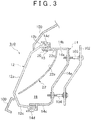
- FIG. 3 is a sectional view of a vehicle lamp fixture 310 according to another example embodiment not forming part of the invention. Constituent elements of this vehicle lamp fixture 310 that are similar or correspond to constituent elements of the vehicle lamp fixture 10 shown in FIGS. 1 and 2 will be denoted by like reference characters and redundant descriptions of those elements will be appropriately omitted.
- circuit board 20 and the reflector 22 are attached directly onto an inside surface 14e of the upper portion 14b of the lamp body 14.
- the method by which circuit board 20 and the reflector 22 are fixed to the upper portion 14b is not particularly limited. That is, the circuit board 20 and the reflector 22 may be fastened by a screw, fixed by adhesive, or thermally caulked, or the like.
- circuit board 20 to which the LED 18 is mounted, and the reflector 22 are both attached to the upper portion 14b of the lamp body 14, which makes it easier to position the LED 18 and the reflector 22, so the assembly time can be reduced and the optical precision can be improved.
- FIG. 4 is a sectional view of a vehicle lamp fixture 410 according to yet another example embodiment of the invention. Constituent elements of this vehicle lamp fixture 410 that are similar or correspond to constituent elements of the vehicle lamp fixture 10 shown in FIGS. 1 and 2 will also be denoted by like reference characters and redundant descriptions of those elements will be appropriately omitted.
- the circuit board 20 to which the LED 18 is mounted is attached to the inside surface 12f of the upper portion 12b of the front cover 12 via the attaching portion 22b of the reflector 22. That is, the circuit board 20 is attached to the inside surface 12f of the upper portion 12b of the front cover 12, with the attaching portion 22b of the reflector 22 sandwiched in between.
- the method by which the circuit board 20 and the reflector 22 are fixed to the upper portion 14b is not particularly limited. That is, the circuit board 20 and the reflector 22 may be fastened by a screw, fixed by adhesive, or thermally caulked, or the like.
- the structure of the lamp fixture is able to be simplified.
- the circuit board 20 on which the LED 18 is mounted, and the reflector 22 are both attached to the upper portion 12b of the front cover 12, which makes it easier to position the LED 18 and the reflector 22, so the assembly time can be reduced and the optical precision can be improved.
- the attaching portion 22b of the reflector 22 functions as a heat sink by being sandwiched between the circuit board 20 and the upper portion 12b of the front cover 12, so the heat generated by the LED 18 is able to be better dissipated.
- the reflector 22 or at least the attaching portion 22b of the reflector 22 is preferably made of material having a good heat dissipation quality such as metal.
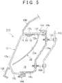
- FIG 5 is a sectional view of a vehicle lamp fixture 510 according to still another example embodiment of the invention.
- Constituent elements of this vehicle lamp fixture 510 that are similar or correspond to constituent elements of the vehicle lamp fixture 10 shown in FIGS. 1 and 2 will also be denoted by like reference characters and redundant descriptions of those elements will be appropriately omitted.
- the circuit board 20 on which the LED 18 is mounted is attached to the inside surface 12f of the upper portion 12b of the front cover 12 via a metal plate 19. That is, the circuit board 20 is attached to the inside surface 12f of the upper portion 12b of the front cover 12, with the metal plate 19 sandwiched in between.
- the method by which the circuit board 20 and the metal plate 19 are fixed to the upper portion 14b is not particularly limited. That is, the circuit board 20 and the metal plate 19 may be fastened by a screw, fixed by adhesive, or thermally caulked, or the like.
- the structure of the lamp fixture is able to be simplified.
- the circuit board 20 to which the LED 18 is mounted, and the reflector 22 are both attached to the upper portion 12b of the front cover 12, which makes it easier to position the LED 18 and the reflector 22, so the assembly time can be reduced and the optical precision can be improved.
- the metal plate 19 functions as a heat sink by being sandwiched between the circuit board 20 and the upper portion 12b of the front cover 12, so the heat generated by the LED 18 is able to be better dissipated.
- the metal plate 19 may also be a member having a function to conduct electricity to the LED 18, such as a bus bar.
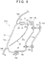
- FIG. 6 is a sectional view of a vehicle lamp fixture 610 according to yet another example embodiment of the invention. Constituent elements of this vehicle lamp fixture 610 that are similar or correspond to constituent elements of the vehicle lamp fixture 10 shown in FIGS. 1 and 2 will also be denoted by like reference characters and redundant descriptions of those elements will be appropriately omitted.
- a metal heat sink 21 is integrally formed on a portion of the upper portion 12b of the front cover 12, and the circuit board 20 to which the LED 18 is mounted is attached to this heat sink 21.
- the heat sink 21 may be integrally formed with the upper portion 12b of the front cover 12 using insert molding, for example.
- the method by which the circuit board 20 is fixed to the heat sink 21 is not particularly limited. That is, the circuit board 20 may be fastened by a screw, fixed by adhesive, or thermally caulked, or the like.
- the structure of the lamp fixture is able to be simplified.
- the circuit board 20 to which the LED 18 is mounted, and the reflector 22 are both attached to the upper portion 12b of the front cover 12, which makes it easier to position the LED 18 and the reflector 22, so the assembly time can be reduced and the optical precision can be improved.
- the circuit board 20 is attached to the heat sink 21 formed on the upper portion 12b of the front cover 12, so heat generated by the LED 18 is able to be even better dissipated. As a result, an LED 18 of even higher power can be used.
- FIG. 7 is a sectional view of a vehicle lamp fixture 710 according to still yet another example embodiment of the invention. Constituent elements of this vehicle lamp fixture 710 that are similar or correspond to constituent elements of the vehicle lamp fixture 10 shown in FIGS. 1 and 2 will also be denoted by like reference characters and redundant descriptions of those elements will be appropriately omitted.
- the circuit board 20 to which the LED 18 is mounted is attached to the inside surface 12f of the upper portion 12b of the front cover 12.
- the method by which the circuit board 20 is fixed to the upper portion 14b is not particularly limited. That is, the circuit board 20 may be fastened by a screw, fixed by adhesive, or thermally caulked, or the like.
- the attaching portion 22b of the reflector 22 is fixed on the circuit board 20.
- a positioning protrusion 22c is formed on the attaching portion 22b. Inserting this positioning protrusion 22c into a positioning recessed portion 20a provided on the circuit board 20 enables the reflector 22 to be properly positioned with respect to the circuit board 20.
- the method by which the attaching portion 22b is fixed to the circuit board 20 is not particularly limited. That is, the attaching portion 22b may be fastened by a screw, fixed by adhesive, or thermally caulked, or the like.
- the LED 18 and the reflector 22 are attached onto the circuit board 20, so the positioning accuracy of the LED 18 and the reflector 22 can be increased, and the optical precision can be improved.
- FIG. 8 is a sectional view of a vehicle lamp fixture 810 according to another example embodiment not forming part of the invention. Constituent elements of this vehicle lamp fixture 810 that are similar or correspond to constituent elements of the vehicle lamp fixture 10 shown in FIGS. 1 and 2 will also be denoted by like reference characters and redundant descriptions of those elements will be appropriately omitted.
- a front surface of the back portion 14a of the lamp body 14 is formed as the reflective portion 22a. That is, the back portion 14a of the lamp body 14 also serves as the reflector.
- the upper portion 14b extends rearward from the upper end portion of the back portion 14a of the lamp body 14, and the circuit board 20 is fixed to the upper portion 14b by a screw 812.
- the method by which the circuit board 20 is fixed to the upper portion 14b is not particularly limited. That is, the circuit board 20 may be fastened by a screw, fixed by adhesive, or thermally caulked, or the like. The circuit board 20 is brought close to the upper portion 12b of the front cover 12, but not so close as to interfere with the upper portion 12b.
- the back portion 14a of the lamp body 14 also serves as the reflector, so the number of parts can be further reduced, and in addition, the positioning accuracy of the LED 18 and the reflective portion 22a can be increased, and the optical precision can be improved.
- the vehicle lamp fixture 810 according to this example embodiment is also advantageous in that heat is able to be exhausted outside of the lamp chamber 16 well.
- an LED is used as the light source, but a semiconductor light-emitting device such as a semiconductor laser, for example, may also be used.
- the vehicle lamp fixture of the invention is applied to a small transportation device such as a personal mobility vehicle, but the vehicle lamp fixture of the invention may also be applied to a transportation device, such as a two-wheeled vehicle or an electric vehicle, for example, in which there is no other large heat source in the position where the vehicle lamp fixture is attached.
Landscapes
- Engineering & Computer Science (AREA)
- General Engineering & Computer Science (AREA)
- Physics & Mathematics (AREA)
- Microelectronics & Electronic Packaging (AREA)
- Optics & Photonics (AREA)
- Non-Portable Lighting Devices Or Systems Thereof (AREA)
- Fastening Of Light Sources Or Lamp Holders (AREA)
Claims (5)
- Appareil d'éclairage de dispositif de transport comprenant :un dispositif d'émission de lumière à semi-conducteurs (18) ;une carte de circuit (20) sur laquelle le dispositif d'émission de lumière à semi-conducteur (18) est monté ;un corps de lampe (14) ; etun couvercle avant (12) qui couvre une ouverture du corps de lampe (14),dans lequel le dispositif d'émission de lumière à semi-conducteur (18) et la carte de circuit (20) sont logées à l'intérieur d'une chambre de lampe (16) formée par le corps de lampe (14) et le couvercle avant (12),caractérisé en ce quela carte de circuit (20) est fixée sur une surface intérieure (12f) d'une partie supérieure (12b) du couvercle avant (12).
- Appareil d'éclairage de dispositif de transport (10) selon la revendication 1, caractérisé en ce qu'il comprend en outre un réflecteur (22) qui réfléchit la lumière émise depuis le dispositif d'émission de lumière à semi-conducteur (18) devant l'appareil d'éclairage, dans lequel le réflecteur (22) est fixé sur le couvercle avant (12).
- Appareil d'éclairage de dispositif de transport (10) selon la revendication 2, dans lequel
le réflecteur (22) inclut une partie réflective pour réfléchir la lumière venant du dispositif d'émission de lumière à semi-conducteur (18), et une partie de fixation (22b) pour fixer le réflecteur (22) sur le couvercle avant (12) ; et
la carte de circuit (20) est fixée sur le couvercle avant (12) via la partie de fixation (22b) du réflecteur (22). - Appareil d'éclairage de dispositif de transport (10) selon la revendication 1 ou 2, dans lequel un dissipateur thermique (21) est formé sur une partie de la partie supérieure (12b) du couvercle avant (12), et la carte de circuit (20) est fixée sur le dissipateur thermique (21).
- Appareil d'éclairage de dispositif de transport (10) selon l'une quelconque des revendications 1 à 4, dans lequel l'appareil d'éclairage de dispositif de transport (10) peut être monté sur un dispositif de transport qui n'a pas une autre source de chaleur qui est différente de l'appareil d'éclairage de dispositif de transport (10), et qui est située autour d'une position déterminée où l'appareil d'éclairage est fixé.
Applications Claiming Priority (1)
| Application Number | Priority Date | Filing Date | Title |
|---|---|---|---|
| JP2012131536A JP5990410B2 (ja) | 2012-06-11 | 2012-06-11 | 移動体用灯具 |
Publications (3)
| Publication Number | Publication Date |
|---|---|
| EP2674664A2 EP2674664A2 (fr) | 2013-12-18 |
| EP2674664A3 EP2674664A3 (fr) | 2016-04-27 |
| EP2674664B1 true EP2674664B1 (fr) | 2018-02-21 |
Family
ID=48625814
Family Applications (1)
| Application Number | Title | Priority Date | Filing Date |
|---|---|---|---|
| EP13171213.5A Not-in-force EP2674664B1 (fr) | 2012-06-11 | 2013-06-10 | Lampe pour un véhicule automobile |
Country Status (4)
| Country | Link |
|---|---|
| US (1) | US9255680B2 (fr) |
| EP (1) | EP2674664B1 (fr) |
| JP (1) | JP5990410B2 (fr) |
| CN (1) | CN103486510A (fr) |
Families Citing this family (11)
| Publication number | Priority date | Publication date | Assignee | Title |
|---|---|---|---|---|
| DE102013104190A1 (de) * | 2013-04-25 | 2014-10-30 | Hella Kgaa Hueck & Co. | Modulbaugruppe zur Anordnung in einem Scheinwerfer |
| DE102014109114B4 (de) * | 2014-06-30 | 2024-04-25 | HELLA GmbH & Co. KGaA | Anordnung eines Kühlkörpers in einem Scheinwerfer |
| FR3032516B1 (fr) * | 2015-02-06 | 2021-04-16 | Valeo Vision | Dispositif reflecteur d'un module lumineux avec blindage electromagnetique |
| US10337717B2 (en) * | 2015-03-31 | 2019-07-02 | Koito Manufacturing Co., Ltd. | Light source unit, method of manufacturing the same, and vehicle lamp |
| CN105570792B (zh) * | 2016-02-16 | 2018-03-23 | 上海小糸车灯有限公司 | 一种汽车照明灯具的led近光模组 |
| JP6695165B2 (ja) * | 2016-02-23 | 2020-05-20 | 株式会社小糸製作所 | 車両用灯具ユニット |
| JP6747886B2 (ja) * | 2016-06-23 | 2020-08-26 | スタンレー電気株式会社 | 車両用灯具 |
| DE102017124227B4 (de) * | 2017-10-18 | 2019-09-05 | Dr. Ing. H.C. F. Porsche Aktiengesellschaft | Fahrzeugteilstruktur und Kraftfahrzeug |
| DE102018105753A1 (de) * | 2018-03-13 | 2019-09-19 | Automotive Lighting Reutlingen Gmbh | Fahrzeugscheinwerfer |
| WO2020236894A1 (fr) | 2019-05-20 | 2020-11-26 | The Regents Of The University Of California | Compositions et procédés d'administration cellulaire |
| DE102023136305A1 (de) * | 2023-12-21 | 2025-06-26 | HELLA GmbH & Co. KGaA | Lichtmodul für eine Kraftfahrzeug-Beleuchtungseinrichtung |
Family Cites Families (20)
| Publication number | Priority date | Publication date | Assignee | Title |
|---|---|---|---|---|
| US4929866A (en) * | 1987-11-17 | 1990-05-29 | Mitsubishi Cable Industries, Ltd. | Light emitting diode lamp |
| JP4339028B2 (ja) | 2003-06-19 | 2009-10-07 | 株式会社小糸製作所 | 灯具ユニットおよび車両用前照灯 |
| JP4468662B2 (ja) * | 2003-07-30 | 2010-05-26 | サカエ理研工業株式会社 | ターンシグナルランプ付きドアミラー装置 |
| JP4251941B2 (ja) * | 2003-08-08 | 2009-04-08 | 三菱電機株式会社 | ヘッドランプ |
| US7329033B2 (en) * | 2005-10-25 | 2008-02-12 | Visteon Global Technologies, Inc. | Convectively cooled headlamp assembly |
| US7513665B2 (en) * | 2006-05-16 | 2009-04-07 | Visteon Global Technologies, Inc. | Headlamp module and headlamp assembly with internally reflecting translucent member |
| TWM333518U (en) * | 2007-10-12 | 2008-06-01 | Dosun Solar Technology Co Ltd | The LED lamps and lanterns with two illumination areas |
| DE102007050924B4 (de) * | 2007-10-23 | 2009-11-26 | Oechsler Ag | LED-bestückter Leuchtenmodul, insbesondere für Kraftfahrzeuge |
| JP5115146B2 (ja) * | 2007-10-24 | 2013-01-09 | 株式会社デンソー | 車両制御装置 |
| CN201143906Y (zh) * | 2007-11-16 | 2008-11-05 | 上海干巷汽车镜(集团)有限公司 | 一种采用导光板转向灯的汽车外后视镜 |
| JP5405043B2 (ja) | 2008-04-22 | 2014-02-05 | 株式会社小糸製作所 | 車両用灯具 |
| CN101592303B (zh) | 2008-05-28 | 2012-12-26 | 奥斯兰姆施尔凡尼亚公司 | 用于机动车后组合灯的后载式发光二极管模块 |
| JP5349933B2 (ja) * | 2008-12-05 | 2013-11-20 | 株式会社小糸製作所 | 車両用灯具 |
| JP2011028906A (ja) * | 2009-07-22 | 2011-02-10 | Stanley Electric Co Ltd | 車両用led灯具 |
| JP2011040247A (ja) * | 2009-08-10 | 2011-02-24 | Koito Mfg Co Ltd | 車両用前照灯の灯具ユニット |
| JP5390372B2 (ja) * | 2009-12-25 | 2014-01-15 | 株式会社小糸製作所 | 光源ユニット及び車輌用灯具 |
| JP2011198757A (ja) * | 2010-02-26 | 2011-10-06 | Panasonic Electric Works Co Ltd | 照明装置 |
| JP5526966B2 (ja) * | 2010-04-16 | 2014-06-18 | 日産自動車株式会社 | 車両用灯具 |
| JP5514666B2 (ja) * | 2010-08-09 | 2014-06-04 | 株式会社小糸製作所 | 車両用前照灯 |
| JP5622524B2 (ja) * | 2010-10-27 | 2014-11-12 | 株式会社小糸製作所 | 車両用灯具 |
-
2012
- 2012-06-11 JP JP2012131536A patent/JP5990410B2/ja active Active
-
2013
- 2013-06-07 CN CN201310225010.0A patent/CN103486510A/zh active Pending
- 2013-06-07 US US13/912,685 patent/US9255680B2/en active Active
- 2013-06-10 EP EP13171213.5A patent/EP2674664B1/fr not_active Not-in-force
Non-Patent Citations (1)
| Title |
|---|
| None * |
Also Published As
| Publication number | Publication date |
|---|---|
| EP2674664A2 (fr) | 2013-12-18 |
| EP2674664A3 (fr) | 2016-04-27 |
| JP2013257950A (ja) | 2013-12-26 |
| US20130329443A1 (en) | 2013-12-12 |
| US9255680B2 (en) | 2016-02-09 |
| CN103486510A (zh) | 2014-01-01 |
| JP5990410B2 (ja) | 2016-09-14 |
Similar Documents
| Publication | Publication Date | Title |
|---|---|---|
| EP2674664B1 (fr) | Lampe pour un véhicule automobile | |
| US7798690B2 (en) | Vehicle headlamp | |
| CN102954420B (zh) | 车辆用灯具 | |
| KR100910054B1 (ko) | Led방열 장치 | |
| US9739438B2 (en) | Vehicle lamp | |
| US20130265793A1 (en) | Lighting apparatus | |
| US9829176B2 (en) | Lamp | |
| CN104165315B (zh) | 车辆用灯具 | |
| EP2518393B1 (fr) | Lampe véhiculaire | |
| CN103486554A (zh) | 光源单元 | |
| HUE029602T2 (en) | Illuminating device | |
| US20130141930A1 (en) | Vehicular headlamp | |
| JP6791684B2 (ja) | 車輌用灯具 | |
| US20090279318A1 (en) | Vehicle headlight assembly | |
| JP5614001B2 (ja) | 車両用灯具 | |
| JP2008195284A (ja) | 車両用灯具 | |
| US8439538B2 (en) | Vehicle light | |
| JPWO2020085044A1 (ja) | 車両用灯具 | |
| JP5854703B2 (ja) | 車両用灯具のカプラ固定構造 | |
| JP6150106B2 (ja) | 車両用灯具 | |
| EP2998646B1 (fr) | Phare pour véhicule | |
| CN111556945A (zh) | 车辆用前照灯 | |
| JP2013229131A (ja) | 車両用灯具のセパレータ固定構造 | |
| CN103867988A (zh) | 用于机动车前照灯的发光装置和配备有所述装置的前照灯 | |
| JP6349689B2 (ja) | 車両用灯具 |
Legal Events
| Date | Code | Title | Description |
|---|---|---|---|
| PUAI | Public reference made under article 153(3) epc to a published international application that has entered the european phase |
Free format text: ORIGINAL CODE: 0009012 |
|
| 17P | Request for examination filed |
Effective date: 20130610 |
|
| AK | Designated contracting states |
Kind code of ref document: A2 Designated state(s): AL AT BE BG CH CY CZ DE DK EE ES FI FR GB GR HR HU IE IS IT LI LT LU LV MC MK MT NL NO PL PT RO RS SE SI SK SM TR |
|
| AX | Request for extension of the european patent |
Extension state: BA ME |
|
| PUAL | Search report despatched |
Free format text: ORIGINAL CODE: 0009013 |
|
| AK | Designated contracting states |
Kind code of ref document: A3 Designated state(s): AL AT BE BG CH CY CZ DE DK EE ES FI FR GB GR HR HU IE IS IT LI LT LU LV MC MK MT NL NO PL PT RO RS SE SI SK SM TR |
|
| AX | Request for extension of the european patent |
Extension state: BA ME |
|
| RIC1 | Information provided on ipc code assigned before grant |
Ipc: F21S 8/10 20060101AFI20160322BHEP |
|
| GRAP | Despatch of communication of intention to grant a patent |
Free format text: ORIGINAL CODE: EPIDOSNIGR1 |
|
| INTG | Intention to grant announced |
Effective date: 20171009 |
|
| GRAS | Grant fee paid |
Free format text: ORIGINAL CODE: EPIDOSNIGR3 |
|
| GRAA | (expected) grant |
Free format text: ORIGINAL CODE: 0009210 |
|
| RAP1 | Party data changed (applicant data changed or rights of an application transferred) |
Owner name: KOITO MANUFACTURING CO., LTD. |
|
| AK | Designated contracting states |
Kind code of ref document: B1 Designated state(s): AL AT BE BG CH CY CZ DE DK EE ES FI FR GB GR HR HU IE IS IT LI LT LU LV MC MK MT NL NO PL PT RO RS SE SI SK SM TR |
|
| REG | Reference to a national code |
Ref country code: GB Ref legal event code: FG4D |
|
| REG | Reference to a national code |
Ref country code: CH Ref legal event code: EP |
|
| REG | Reference to a national code |
Ref country code: DE Ref legal event code: R096 Ref document number: 602013033257 Country of ref document: DE Ref country code: AT Ref legal event code: REF Ref document number: 972143 Country of ref document: AT Kind code of ref document: T Effective date: 20180315 |
|
| REG | Reference to a national code |
Ref country code: IE Ref legal event code: FG4D |
|
| REG | Reference to a national code |
Ref country code: FR Ref legal event code: PLFP Year of fee payment: 6 |
|
| REG | Reference to a national code |
Ref country code: NL Ref legal event code: MP Effective date: 20180221 |
|
| REG | Reference to a national code |
Ref country code: LT Ref legal event code: MG4D |
|
| REG | Reference to a national code |
Ref country code: AT Ref legal event code: MK05 Ref document number: 972143 Country of ref document: AT Kind code of ref document: T Effective date: 20180221 |
|
| PG25 | Lapsed in a contracting state [announced via postgrant information from national office to epo] |
Ref country code: NL Free format text: LAPSE BECAUSE OF FAILURE TO SUBMIT A TRANSLATION OF THE DESCRIPTION OR TO PAY THE FEE WITHIN THE PRESCRIBED TIME-LIMIT Effective date: 20180221 Ref country code: LT Free format text: LAPSE BECAUSE OF FAILURE TO SUBMIT A TRANSLATION OF THE DESCRIPTION OR TO PAY THE FEE WITHIN THE PRESCRIBED TIME-LIMIT Effective date: 20180221 Ref country code: ES Free format text: LAPSE BECAUSE OF FAILURE TO SUBMIT A TRANSLATION OF THE DESCRIPTION OR TO PAY THE FEE WITHIN THE PRESCRIBED TIME-LIMIT Effective date: 20180221 Ref country code: HR Free format text: LAPSE BECAUSE OF FAILURE TO SUBMIT A TRANSLATION OF THE DESCRIPTION OR TO PAY THE FEE WITHIN THE PRESCRIBED TIME-LIMIT Effective date: 20180221 Ref country code: NO Free format text: LAPSE BECAUSE OF FAILURE TO SUBMIT A TRANSLATION OF THE DESCRIPTION OR TO PAY THE FEE WITHIN THE PRESCRIBED TIME-LIMIT Effective date: 20180521 Ref country code: CY Free format text: LAPSE BECAUSE OF FAILURE TO SUBMIT A TRANSLATION OF THE DESCRIPTION OR TO PAY THE FEE WITHIN THE PRESCRIBED TIME-LIMIT Effective date: 20180221 Ref country code: FI Free format text: LAPSE BECAUSE OF FAILURE TO SUBMIT A TRANSLATION OF THE DESCRIPTION OR TO PAY THE FEE WITHIN THE PRESCRIBED TIME-LIMIT Effective date: 20180221 |
|
| PG25 | Lapsed in a contracting state [announced via postgrant information from national office to epo] |
Ref country code: AT Free format text: LAPSE BECAUSE OF FAILURE TO SUBMIT A TRANSLATION OF THE DESCRIPTION OR TO PAY THE FEE WITHIN THE PRESCRIBED TIME-LIMIT Effective date: 20180221 Ref country code: GR Free format text: LAPSE BECAUSE OF FAILURE TO SUBMIT A TRANSLATION OF THE DESCRIPTION OR TO PAY THE FEE WITHIN THE PRESCRIBED TIME-LIMIT Effective date: 20180522 Ref country code: SE Free format text: LAPSE BECAUSE OF FAILURE TO SUBMIT A TRANSLATION OF THE DESCRIPTION OR TO PAY THE FEE WITHIN THE PRESCRIBED TIME-LIMIT Effective date: 20180221 Ref country code: LV Free format text: LAPSE BECAUSE OF FAILURE TO SUBMIT A TRANSLATION OF THE DESCRIPTION OR TO PAY THE FEE WITHIN THE PRESCRIBED TIME-LIMIT Effective date: 20180221 Ref country code: BG Free format text: LAPSE BECAUSE OF FAILURE TO SUBMIT A TRANSLATION OF THE DESCRIPTION OR TO PAY THE FEE WITHIN THE PRESCRIBED TIME-LIMIT Effective date: 20180521 Ref country code: RS Free format text: LAPSE BECAUSE OF FAILURE TO SUBMIT A TRANSLATION OF THE DESCRIPTION OR TO PAY THE FEE WITHIN THE PRESCRIBED TIME-LIMIT Effective date: 20180221 |
|
| PG25 | Lapsed in a contracting state [announced via postgrant information from national office to epo] |
Ref country code: RO Free format text: LAPSE BECAUSE OF FAILURE TO SUBMIT A TRANSLATION OF THE DESCRIPTION OR TO PAY THE FEE WITHIN THE PRESCRIBED TIME-LIMIT Effective date: 20180221 Ref country code: IT Free format text: LAPSE BECAUSE OF FAILURE TO SUBMIT A TRANSLATION OF THE DESCRIPTION OR TO PAY THE FEE WITHIN THE PRESCRIBED TIME-LIMIT Effective date: 20180221 Ref country code: PL Free format text: LAPSE BECAUSE OF FAILURE TO SUBMIT A TRANSLATION OF THE DESCRIPTION OR TO PAY THE FEE WITHIN THE PRESCRIBED TIME-LIMIT Effective date: 20180221 Ref country code: AL Free format text: LAPSE BECAUSE OF FAILURE TO SUBMIT A TRANSLATION OF THE DESCRIPTION OR TO PAY THE FEE WITHIN THE PRESCRIBED TIME-LIMIT Effective date: 20180221 Ref country code: EE Free format text: LAPSE BECAUSE OF FAILURE TO SUBMIT A TRANSLATION OF THE DESCRIPTION OR TO PAY THE FEE WITHIN THE PRESCRIBED TIME-LIMIT Effective date: 20180221 |
|
| PGFP | Annual fee paid to national office [announced via postgrant information from national office to epo] |
Ref country code: GB Payment date: 20180606 Year of fee payment: 6 |
|
| REG | Reference to a national code |
Ref country code: DE Ref legal event code: R097 Ref document number: 602013033257 Country of ref document: DE |
|
| PG25 | Lapsed in a contracting state [announced via postgrant information from national office to epo] |
Ref country code: DK Free format text: LAPSE BECAUSE OF FAILURE TO SUBMIT A TRANSLATION OF THE DESCRIPTION OR TO PAY THE FEE WITHIN THE PRESCRIBED TIME-LIMIT Effective date: 20180221 Ref country code: SM Free format text: LAPSE BECAUSE OF FAILURE TO SUBMIT A TRANSLATION OF THE DESCRIPTION OR TO PAY THE FEE WITHIN THE PRESCRIBED TIME-LIMIT Effective date: 20180221 Ref country code: CZ Free format text: LAPSE BECAUSE OF FAILURE TO SUBMIT A TRANSLATION OF THE DESCRIPTION OR TO PAY THE FEE WITHIN THE PRESCRIBED TIME-LIMIT Effective date: 20180221 Ref country code: SK Free format text: LAPSE BECAUSE OF FAILURE TO SUBMIT A TRANSLATION OF THE DESCRIPTION OR TO PAY THE FEE WITHIN THE PRESCRIBED TIME-LIMIT Effective date: 20180221 |
|
| PLBE | No opposition filed within time limit |
Free format text: ORIGINAL CODE: 0009261 |
|
| STAA | Information on the status of an ep patent application or granted ep patent |
Free format text: STATUS: NO OPPOSITION FILED WITHIN TIME LIMIT |
|
| RIC2 | Information provided on ipc code assigned after grant |
Ipc: F21S 8/10 20181130AFI20160322BHEP |
|
| REG | Reference to a national code |
Ref country code: CH Ref legal event code: PK Free format text: BERICHTIGUNGEN |
|
| 26N | No opposition filed |
Effective date: 20181122 |
|
| REG | Reference to a national code |
Ref country code: CH Ref legal event code: PK Free format text: BERICHTIGUNGEN Ref country code: CH Ref legal event code: PL |
|
| RIC2 | Information provided on ipc code assigned after grant |
Ipc: F21S 8/10 20060101AFI20160322BHEP |
|
| PG25 | Lapsed in a contracting state [announced via postgrant information from national office to epo] |
Ref country code: SI Free format text: LAPSE BECAUSE OF FAILURE TO SUBMIT A TRANSLATION OF THE DESCRIPTION OR TO PAY THE FEE WITHIN THE PRESCRIBED TIME-LIMIT Effective date: 20180221 |
|
| REG | Reference to a national code |
Ref country code: BE Ref legal event code: MM Effective date: 20180630 |
|
| REG | Reference to a national code |
Ref country code: IE Ref legal event code: MM4A |
|
| PG25 | Lapsed in a contracting state [announced via postgrant information from national office to epo] |
Ref country code: LU Free format text: LAPSE BECAUSE OF NON-PAYMENT OF DUE FEES Effective date: 20180610 Ref country code: MC Free format text: LAPSE BECAUSE OF FAILURE TO SUBMIT A TRANSLATION OF THE DESCRIPTION OR TO PAY THE FEE WITHIN THE PRESCRIBED TIME-LIMIT Effective date: 20180221 |
|
| PG25 | Lapsed in a contracting state [announced via postgrant information from national office to epo] |
Ref country code: LI Free format text: LAPSE BECAUSE OF NON-PAYMENT OF DUE FEES Effective date: 20180630 Ref country code: CH Free format text: LAPSE BECAUSE OF NON-PAYMENT OF DUE FEES Effective date: 20180630 Ref country code: IE Free format text: LAPSE BECAUSE OF NON-PAYMENT OF DUE FEES Effective date: 20180610 |
|
| PG25 | Lapsed in a contracting state [announced via postgrant information from national office to epo] |
Ref country code: BE Free format text: LAPSE BECAUSE OF NON-PAYMENT OF DUE FEES Effective date: 20180630 |
|
| PGFP | Annual fee paid to national office [announced via postgrant information from national office to epo] |
Ref country code: DE Payment date: 20190528 Year of fee payment: 7 |
|
| PGFP | Annual fee paid to national office [announced via postgrant information from national office to epo] |
Ref country code: FR Payment date: 20190510 Year of fee payment: 7 |
|
| PG25 | Lapsed in a contracting state [announced via postgrant information from national office to epo] |
Ref country code: MT Free format text: LAPSE BECAUSE OF NON-PAYMENT OF DUE FEES Effective date: 20180610 |
|
| GBPC | Gb: european patent ceased through non-payment of renewal fee |
Effective date: 20190610 |
|
| PG25 | Lapsed in a contracting state [announced via postgrant information from national office to epo] |
Ref country code: TR Free format text: LAPSE BECAUSE OF FAILURE TO SUBMIT A TRANSLATION OF THE DESCRIPTION OR TO PAY THE FEE WITHIN THE PRESCRIBED TIME-LIMIT Effective date: 20180221 |
|
| PG25 | Lapsed in a contracting state [announced via postgrant information from national office to epo] |
Ref country code: GB Free format text: LAPSE BECAUSE OF NON-PAYMENT OF DUE FEES Effective date: 20190610 |
|
| PG25 | Lapsed in a contracting state [announced via postgrant information from national office to epo] |
Ref country code: HU Free format text: LAPSE BECAUSE OF FAILURE TO SUBMIT A TRANSLATION OF THE DESCRIPTION OR TO PAY THE FEE WITHIN THE PRESCRIBED TIME-LIMIT; INVALID AB INITIO Effective date: 20130610 Ref country code: PT Free format text: LAPSE BECAUSE OF FAILURE TO SUBMIT A TRANSLATION OF THE DESCRIPTION OR TO PAY THE FEE WITHIN THE PRESCRIBED TIME-LIMIT Effective date: 20180221 |
|
| PG25 | Lapsed in a contracting state [announced via postgrant information from national office to epo] |
Ref country code: MK Free format text: LAPSE BECAUSE OF NON-PAYMENT OF DUE FEES Effective date: 20180221 |
|
| PG25 | Lapsed in a contracting state [announced via postgrant information from national office to epo] |
Ref country code: IS Free format text: LAPSE BECAUSE OF FAILURE TO SUBMIT A TRANSLATION OF THE DESCRIPTION OR TO PAY THE FEE WITHIN THE PRESCRIBED TIME-LIMIT Effective date: 20180621 |
|
| REG | Reference to a national code |
Ref country code: DE Ref legal event code: R119 Ref document number: 602013033257 Country of ref document: DE |
|
| PG25 | Lapsed in a contracting state [announced via postgrant information from national office to epo] |
Ref country code: FR Free format text: LAPSE BECAUSE OF NON-PAYMENT OF DUE FEES Effective date: 20200630 |
|
| PG25 | Lapsed in a contracting state [announced via postgrant information from national office to epo] |
Ref country code: DE Free format text: LAPSE BECAUSE OF NON-PAYMENT OF DUE FEES Effective date: 20210101 |