EP2674775A1 - Système de localisation sans fil - Google Patents
Système de localisation sans fil Download PDFInfo
- Publication number
- EP2674775A1 EP2674775A1 EP13184123.1A EP13184123A EP2674775A1 EP 2674775 A1 EP2674775 A1 EP 2674775A1 EP 13184123 A EP13184123 A EP 13184123A EP 2674775 A1 EP2674775 A1 EP 2674775A1
- Authority
- EP
- European Patent Office
- Prior art keywords
- nodes
- node
- round trip
- location
- localisation
- Prior art date
- Legal status (The legal status is an assumption and is not a legal conclusion. Google has not performed a legal analysis and makes no representation as to the accuracy of the status listed.)
- Granted
Links
Images



Classifications
-
- G—PHYSICS
- G01—MEASURING; TESTING
- G01S—RADIO DIRECTION-FINDING; RADIO NAVIGATION; DETERMINING DISTANCE OR VELOCITY BY USE OF RADIO WAVES; LOCATING OR PRESENCE-DETECTING BY USE OF THE REFLECTION OR RERADIATION OF RADIO WAVES; ANALOGOUS ARRANGEMENTS USING OTHER WAVES
- G01S5/00—Position-fixing by co-ordinating two or more direction or position line determinations; Position-fixing by co-ordinating two or more distance determinations
- G01S5/02—Position-fixing by co-ordinating two or more direction or position line determinations; Position-fixing by co-ordinating two or more distance determinations using radio waves
- G01S5/14—Determining absolute distances from a plurality of spaced points of known location
-
- G—PHYSICS
- G01—MEASURING; TESTING
- G01S—RADIO DIRECTION-FINDING; RADIO NAVIGATION; DETERMINING DISTANCE OR VELOCITY BY USE OF RADIO WAVES; LOCATING OR PRESENCE-DETECTING BY USE OF THE REFLECTION OR RERADIATION OF RADIO WAVES; ANALOGOUS ARRANGEMENTS USING OTHER WAVES
- G01S13/00—Systems using the reflection or reradiation of radio waves, e.g. radar systems; Analogous systems using reflection or reradiation of waves whose nature or wavelength is irrelevant or unspecified
- G01S13/87—Combinations of radar systems, e.g. primary radar and secondary radar
- G01S13/876—Combination of several spaced transponders or reflectors of known location for determining the position of a receiver
-
- G—PHYSICS
- G01—MEASURING; TESTING
- G01S—RADIO DIRECTION-FINDING; RADIO NAVIGATION; DETERMINING DISTANCE OR VELOCITY BY USE OF RADIO WAVES; LOCATING OR PRESENCE-DETECTING BY USE OF THE REFLECTION OR RERADIATION OF RADIO WAVES; ANALOGOUS ARRANGEMENTS USING OTHER WAVES
- G01S13/00—Systems using the reflection or reradiation of radio waves, e.g. radar systems; Analogous systems using reflection or reradiation of waves whose nature or wavelength is irrelevant or unspecified
- G01S13/87—Combinations of radar systems, e.g. primary radar and secondary radar
- G01S13/878—Combination of several spaced transmitters or receivers of known location for determining the position of a transponder or a reflector
-
- G—PHYSICS
- G01—MEASURING; TESTING
- G01S—RADIO DIRECTION-FINDING; RADIO NAVIGATION; DETERMINING DISTANCE OR VELOCITY BY USE OF RADIO WAVES; LOCATING OR PRESENCE-DETECTING BY USE OF THE REFLECTION OR RERADIATION OF RADIO WAVES; ANALOGOUS ARRANGEMENTS USING OTHER WAVES
- G01S5/00—Position-fixing by co-ordinating two or more direction or position line determinations; Position-fixing by co-ordinating two or more distance determinations
- G01S5/01—Determining conditions which influence positioning, e.g. radio environment, state of motion or energy consumption
- G01S5/017—Detecting state or type of motion
-
- G—PHYSICS
- G01—MEASURING; TESTING
- G01S—RADIO DIRECTION-FINDING; RADIO NAVIGATION; DETERMINING DISTANCE OR VELOCITY BY USE OF RADIO WAVES; LOCATING OR PRESENCE-DETECTING BY USE OF THE REFLECTION OR RERADIATION OF RADIO WAVES; ANALOGOUS ARRANGEMENTS USING OTHER WAVES
- G01S5/00—Position-fixing by co-ordinating two or more direction or position line determinations; Position-fixing by co-ordinating two or more distance determinations
- G01S5/02—Position-fixing by co-ordinating two or more direction or position line determinations; Position-fixing by co-ordinating two or more distance determinations using radio waves
- G01S5/0205—Details
- G01S5/0218—Multipath in signal reception
-
- G—PHYSICS
- G01—MEASURING; TESTING
- G01S—RADIO DIRECTION-FINDING; RADIO NAVIGATION; DETERMINING DISTANCE OR VELOCITY BY USE OF RADIO WAVES; LOCATING OR PRESENCE-DETECTING BY USE OF THE REFLECTION OR RERADIATION OF RADIO WAVES; ANALOGOUS ARRANGEMENTS USING OTHER WAVES
- G01S5/00—Position-fixing by co-ordinating two or more direction or position line determinations; Position-fixing by co-ordinating two or more distance determinations
- G01S5/02—Position-fixing by co-ordinating two or more direction or position line determinations; Position-fixing by co-ordinating two or more distance determinations using radio waves
- G01S5/0205—Details
- G01S5/0226—Transmitters
-
- G—PHYSICS
- G01—MEASURING; TESTING
- G01S—RADIO DIRECTION-FINDING; RADIO NAVIGATION; DETERMINING DISTANCE OR VELOCITY BY USE OF RADIO WAVES; LOCATING OR PRESENCE-DETECTING BY USE OF THE REFLECTION OR RERADIATION OF RADIO WAVES; ANALOGOUS ARRANGEMENTS USING OTHER WAVES
- G01S5/00—Position-fixing by co-ordinating two or more direction or position line determinations; Position-fixing by co-ordinating two or more distance determinations
- G01S5/02—Position-fixing by co-ordinating two or more direction or position line determinations; Position-fixing by co-ordinating two or more distance determinations using radio waves
- G01S5/0284—Relative positioning
- G01S5/0289—Relative positioning of multiple transceivers, e.g. in ad hoc networks
Definitions
- the present invention relates generally to wireless localisation, and in particular to tracking objects using radio signals based on measurement of the time-of-arrival.
- the most common TOA-based localisation system uses receiving anchor nodes that are hard-wired (cabled) to the processing hardware (e.g. US Patent 6,831,603 ). This greatly simplifies the system as a common clock can be shared, eliminating the problem of frequency and time synchronisation. In some situations, such as where rapid installation is required or the region between receiving nodes is inaccessible or inappropriate for cable installation, cabled connections between anchor nodes are impractical.
- the location of the mobile nodes is estimated in a process known as 'multilateration'.
- the most common technique uses a minimum mean squared error (MMSE) approach. With this technique, 'bad' range data can severely affect the estimated locations of the mobile nodes.
- MMSE minimum mean squared error
- Another technique with a different assumption on the error distribution is based on Projections onto Convex Sets (POCS); however, conventional POCS algorithms do not handle well the case where there is a large intersection region. As with MMSE, the POCS approach is susceptible to bad data due to effects such as multipath reflections, radio interference and fading phenomena.
- a method of computing a round trip delay between a pair of nodes comprising:
- a method of estimating the location of a mobile object using a plurality of ranges between a node associated with said object and respective anchor nodes comprising:
- a method of estimating the location of a mobile object using a plurality of ranges between a node associated with said object and respective anchor nodes comprising:
- a method of estimating the location of a mobile object using a plurality of anchor nodes comprising:
- a system for estimating the location of one or more objects comprising:
- a system for estimating the location of an object comprising:
- the disclosed arrangements include a system for wireless localisation and tracking, and methods that can be used in the disclosed system or other systems.
- the disclosed arrangements estimate object location using multilateration based on measured time-of-arrival (TOA) of radio signals.
- TOA time-of-arrival
- the disclosed arrangements enable more robust processing and hence more accurate location estimation compared to existing systems and methods in the face of bad data due to typical sources of error such as TOA measurement errors (e.g. due to multipath interference or propagation effects), unsynchronised clocks in nodes, time varying propagation delay through the node electronics, and object motion.
- the disclosed system using only low-cost consumer electronic components, is capable of covering large areas (i.e. is not limited to direct radio communication links between all nodes) and is capable of rapid deployment as cabling is not required between any nodes.
- Appendix A contains pseudocode for a robust MMSE algorithm for estimating the location of a mobile node.
- FIG. 1 shows an example of a tracking system 100 within which the disclosed arrangements may be practised, comprising one soccer player 110, several fixed anchor nodes, e.g. 120, surrounding the field, and a location server 130.
- a tracking system 100 within which the disclosed arrangements may be practised, comprising one soccer player 110, several fixed anchor nodes, e.g. 120, surrounding the field, and a location server 130.
- the anchor nodes 120 are wirelessly connected to the location server to simplify deployment (although where convenient a cable or fibre connection can be used and will usually improve system performance).
- the disclosed tracking system comprises:
- the wireless data communication is preferably performed using direct sequence spread spectrum signalling; however, it could be equally well performed using any radio communication protocol (e.g. the 802.11 family of standards).
- Fig. 2 is a flow diagram illustrating a general method 200 of localisation according to the preferred embodiment.
- step 210 certain nodes called beaconing nodes periodically transmit radio signals called beacons that are received by some other nodes called TOA reception nodes that are able to measure the TOA of the beacon.
- the beacons contain a localisation signal designed for accurate measurement of TOA and an optional data payload. While the localisation signal could be a data symbol, better results are obtained using a specially designed localisation signal.
- the mobile nodes may be beaconing nodes and/or TOA reception nodes, and likewise the anchor nodes may be beaconing nodes and/or TOA reception nodes. For example:
- TDMA time division multiple access
- CDMA code division multiple access
- FDMA frequency division multiple access
- the TOA reception nodes measure the TOA for each received beacon, and at step 230 the TOA reception nodes send the TOA data to the location server (preferably via the data payload in their own beacons, or alternatively via other means such as cable, particularly if a TOA reception node is not also a beaconing node).
- the transmit time of beacons is also required, and beaconing nodes can send this to the location server as a data field in the beacon or by other means. There may be other data such as that related to system operation, for protocols, or from sensors, that is also sent to the location server.
- the location server at step 240 applies a localisation algorithm to the received data to estimate the location of the mobile nodes.
- a beaconing node 400 according to the preferred embodiment is illustrated in Fig. 4a .
- the beaconing node 400 has digital electronics 430 to generate a beacon and a module 420 to convert the beacon to analog form for radio transmission using a radio transceiver 410 in step 210 of the method 200.
- the beaconing node 400 also receives data at least to allow synchronisation of TDMA slots, so the data flow in the beaconing node 400 is bidirectional.
- the beacons 450 are scheduled to minimise self-interference and hence maximise localisation accuracy.
- the update rate of a mobile node's location estimate is limited to the rate at which that node transmits beacons.
- the preferred TDMA scheme 500 is illustrated in Fig. 5 .
- Time is divided into slots, e.g. 510, with a beacon being sent in each slot by the node corresponding to the slot label (M1 is mobile node 1, A1 is anchor node 1, etc).
- a slot can be used by plural nodes, provided the minimum radio link hop count between the nodes using the same slot is greater than two (hence not all nodes have the same schedule).
- the slot size will generally be as small as possible, preferably adjustable between 1 ms and 10 ms.
- the update rate of the beacons is determined by the localisation algorithm category.
- all nodes should transmit at least at the minimum localisation update rate.
- the mobile nodes For mobile transmit localisation, the mobile nodes should transmit at the minimum localisation update rate; however the anchor nodes should transmit at the required rate to maintain time synchronisation, which is in turn dependent upon the stability of the local oscillators in each node.
- the slots are grouped in superframes, e.g. 520, as this simplifies the TDMA scheme; however, it is not necessary.
- the schedule of each superframe is generally the same, except for dynamic behaviour in the network (e.g. mobile nodes moving in and out of range).
- the scheduling of beacons into slots can be static or dynamic.
- Static allocation in which the schedule is known in advance by all nodes, is simpler but does not allow slot reuse in multi-hop networks.
- Dynamic allocation entails additional communication overhead, either mutually among the nodes according to a distributed algorithm, or between a scheduling controller (e.g. the location server) and the nodes.
- Coarse time synchronisation is required between all nodes for the TDMA scheme; however, this only needs to be within a fraction of the slot duration (e.g. one percent, or 10 ⁇ s for 1 ms slots), which is readily achieved in nodes designed to measure TOA with high accuracy (typically better than 1 ns).
- the synchronisation time reference is provided by one of the nodes either by fixed allocation or selection by the nodes themselves (the latter alternative providing robustness should the time reference node fail). This time synchronisation is too coarse to be of any assistance for localisation.
- the measurement of the TOA (step 220) is preferably carried out by a TOA reception node according to the method described in the PCT patent application no. PCT/AU2009/000647 .
- any technique for the measurement of TOA may alternatively be used.
- a location server 600 according to the preferred embodiment is illustrated in Fig. 6 .
- the location server 600 comprises an analog radio receiver 610, an analog to digital converter 620, and digital processing electronics 630.
- the location server 600 processes the received data from the TOA reception nodes and uses this information to estimate the location of mobile nodes (step 240).
- the location server 600 may also perform other functions such as performing and/or reporting system diagnostics and recording and formatting sensor data from the system.
- the digital processing electronics 630 on which the location estimation and any other processing are implemented, are therefore more powerful than the digital processing electronics 430 of either an anchor node or a beacon node.
- the digital processing electronics 630 comprises the digital processing electronics 430 of an anchor node connected via a USB interface to a general purpose computer system 300 such as that shown in Fig. 3 , wherein the processing of step 240 may be implemented as software, such as one or more application programs executable within the computer system 300.
- the processing of step 240 is effected by instructions in the software that are carried out within the computer system 300.
- the instructions may be formed as one or more code modules, each for performing one or more particular tasks.
- the software may also be divided into two separate parts, in which a first part and the corresponding code modules performs the location estimation processing and a second part and the corresponding code modules manage an interface between the first part and other systems.
- the computer module 301 also has a local network interface 311 which, via a connection 323, permits coupling of the computer system 300 to a local computer network 322, known as a Local Area Network (LAN).
- LAN Local Area Network
- the local network 322 may also couple to the wide network 320 via a connection 324, which would typically include a so-called "firewall” device or similar functionality.
- the interface 311 may be formed by an Ethernet TM circuit card, a wireless Bluetooth TM or an IEEE 802.11 wireless arrangement.
- the components 305, to 313 of the computer module 301 typically communicate via an interconnected bus 304 and in a manner which results in a conventional mode of operation of the computer system 300 known to those in the relevant art.
- Examples of computers on which the described arrangements can be practised include IBM-PC's and compatibles, Sun Sparcstations, Apple Mac TM or like computer systems evolved therefrom.
- Examples of such media include floppy disks, magnetic tape, CD-ROM, a hard disk drive, a ROM or integrated circuit, a magneto-optical disk, or a computer readable card such as a PCMCIA card and the like, whether or not such devices are internal or external of the computer module 301.
- Examples of computer readable transmission media that may also participate in the provision of instructions and/or data include radio or infra-red transmission channels as well as a network connection to another computer or networked device, and the Internet or Intranets including e-mail transmissions and information recorded on Websites and the like.
- the location server 600 can implement multiple localisation algorithms simultaneously, as in the following exemplary scenarios:
- the steps of the method 700 are mostly carried out by the location server 600, except for TOA measurement steps 715, 752, 735, 770, and 775 which are done by beaconing nodes and TOA reception nodes 400, and the results sent to the location server 600, as shown by the method 200.
- the method 700 starts at step 710 where it is determined whether the propagation delay of the anchor nodes is known from prior calibration. If not, the method 700 proceeds to step 715 at which the TOA at each anchor node from all other anchor nodes is measured. In step 720 the corrected round trip delay between each pair of anchor nodes is computed as described below. Step 725 follows, at which the propagation delay at each anchor node is computed as described below. Next, it is checked at step 730 whether round trip localisation is to be used.
- step 735 measures the TOA at each anchor node from each mobile node.
- Step 740 follows, at which the anchor nodes are time synchronised as described below.
- the Pseudo-Range (see below) between all anchor and mobile nodes is then computed at step 745 as described below, after which at step 750 a robust MMSE-based Time Difference of Arrival (TDOA) algorithm described below is used to estimate the location of each mobile node.
- TDOA Time Difference of Arrival
- step 752 measures the TOA at each anchor node from each mobile node, and vice versa. Then at step 754, the method 700 computes the Corrected Round Trip Delay between each anchor node and each mobile node as described below. Step 756 follows, at which the Pseudo-Range between all anchor and mobile nodes is computed as described below. Finally at step 758 a robust MMSE-based TOA algorithm, described below, is used to estimate the location of each mobile node.
- step 756 computes range rather than pseudo-range, and step 758 would use either a robust MMSE-based or a POCS-based TOA algorithm, to be described below, to estimate the location of each mobile node from the computed ranges.
- the propagation delay at the mobile nodes is unlikely to be known as the propagation delay of the anchor nodes was initially unknown. The method 700 then concludes at step 795.
- step 765 checks whether round trip localisation is to be used. If not, step 770 measures the TOA at each anchor node from all other anchor nodes and all mobile nodes. The method 700 then continues from step 740 as described above.
- step 775 measures the TOA at each anchor node from each mobile node, and vice versa. Then at step 780, the method 700 computes the Corrected Round Trip Delay between each anchor node and each mobile node as in step 754. Step 785 follows, at which the range between all anchor and mobile nodes is computed (assuming the propagation delay at the mobile nodes is known, which is likely since the propagation delay at the anchor nodes is known). Finally at step 790 the robust MMSE- or POCS-based TOA algorithm is used to estimate the location of each mobile node, as in step 758.
- step 785 computes Pseudo-Range rather than range, and step 790 can only use the robust MMSE-based TOA algorithm, as in step 758.
- the method 700 then concludes at step 795.
- the two nodes are labelled as M (typically, but not necessarily, a mobile node) and B (an anchor node).
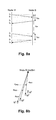
- Node M transmits a beacon first, followed by node B after a delay of ⁇ MB determined by the beacon schedule (see Fig. 5 ). After a delay of ⁇ SF (the superframe length), this sequence is repeated, as illustrated in Fig. 8a .
- the beacons are transmitted at times t 1 , t 3 , t 5 and t 7 , and received at times t 2 , t 4 , t 6 and t 8 .
- the difference between the transmit time and the receive time e.g.
- t 2 - t 1 is the sum of the propagation delay through the transmitter electronics ( ⁇ i tx where i can be M or B), the propagation time through the air ( d ij / c where d ij is distance between the two nodes, c is speed of light, and j can be B or M), and the propagation delay through the receiver electronics ⁇ j rx .
- ⁇ MB terms between a mobile node and multiple anchor nodes it is possible to estimate the velocity of the mobile node without determining range or location.
- the round trip delay measurement requires measurements in both directions between the pair of nodes.
- ⁇ i ⁇ i tx + ⁇ i rx .
- the quantity 2 ⁇ d BM ⁇ 1 c is the corrected round trip delay.
- the quantities T MB and D M (equation (1)) are directly determined from the measured data, and ⁇ MB is known from the beacon TDMA schedule; if not, it can be readily estimated from the TOA data as follows: ⁇ MB ⁇ t 4 M + t 3 B - t 2 B + t 1 M 2
- the location of the mobile node (hence d BM 1 ) is unknown, and the propagation delay ⁇ i for each node may be unknown.
- corrected round trip delay measurements are first made between anchor nodes and mobile nodes (steps 754 and 780).
- the use of round trip delay measurements for removing the requirement for time synchronisation is well known, but using the corrected round trip delay computed as below, the effects of frequency offset and relative motion can also be removed.
- An important feature of this correction for motion and frequency offset is that it is applied locally to each node pair, and no global processing is required. Note that the motion is corrected to the time at which the mobile node transmits, hence all ranges between this mobile node and multiple anchor nodes are corrected to the same time, compensating for the effect of constant velocity motion.
- the propagation delay ⁇ B of the anchor nodes is either known from prior calibration or computed at step 725 using corrected round trip delay measurements between anchor nodes as described below.
- round trip measurements between mobile nodes are not used, but these measurements may be used for other purposes, e.g. cooperative localisation.
- the corrected round trip delay 2 ⁇ d BM ⁇ 1 c (step 780 or 754) is T MB - ⁇ M - ⁇ B - ⁇ MB D M .
- the range between the pair of nodes is therefore computed (step 785 or 756) as: d BM ⁇ c ⁇ T MB - ⁇ M - ⁇ B - ⁇ MB ⁇ D M 2 .
- the location of the mobile node is estimated (step 790 or 758).
- the corrected round trip delay 2 ⁇ d BM ⁇ 1 c + ⁇ M (step 754 or 780) is T MB - ⁇ B - ⁇ MB D M .
- Pre-filtering of the range data improves localisation accuracy by eliminating bad measurements prior to the localisation steps 758 and 790.
- an improved estimate of the true range at any given time can be determined by a variety of filtering and interpolation operations. Applying these operations prior to estimation of the node location using either the POCS or MMSE approaches described below can result in improved estimation accuracy. Because these operations act on the range data before the localisation step, the result is quite different to applying a filter (such as a Kalman filter or non-linear filter) to the estimated locations.
- a filter such as a Kalman filter or non-linear filter
- any of a number of filtering operations can be applied to the range data, taking into account a priori information about the characteristics of the motion of the mobile node.
- filtering may include for example linear filters (e.g. low pass filter and Kalman filter) or non-linear filters (e.g. median filter).
- linear filters e.g. low pass filter and Kalman filter
- non-linear filters e.g. median filter
- a nonlinear filter which replaces infeasible measurements with a value extrapolated from past measurements can be used.
- One embodiment of such a filter limits the maximum difference in range between the minimum range from of any of the previous 5 superframes and the range from the current superframe.
- the same filtering operations can be applied to pseudo-range data between a given mobile node and anchor nodes, as the distance offset between the pseudo-range and the (unknown) true range is the same for each of these measurements.
- the locations x i of the anchor nodes are known.
- Finding the minimising argument of either cost function is a non-linear problem with many solution strategies.
- An initial linear solution followed by one or more non-linear iterations using a Taylor expansion (usually less than five iterations are required) is preferable.
- bad range measurements e.g. ones with a significant bias due to multipath
- An algorithm for doing this is given by the pseudocode in Appendix A.
- the location and the error in the location estimate are computed at line 5. If the error is less than a threshold, or the number of ranges is less than or equal to a minimum number, the "repeat" loop at line 4 terminates. Each range or pseudo-range measurement is then excluded in turn at line 9, which recomputes the location and the error in the location estimate with the remaining range or pseudo-range measurements.
- Equation (9) is based on the simplifying assumption that the noise in the range (or pseudo-range) measurements is independent and identically distributed, which while not strictly true has been found to work very well with real data.
- the GDOP is calculated as a Cramer-Rao lower bound (see e.g. Larsson, E.G., "Cramer-Rao bound analysis of distributed positioning in sensor networks," IEEE Signal Processing Letters, vol. 11, no. 3, pp. 334 - 337, March 2004 ). This calculation depends upon the location of the anchor nodes, and whether or not the mobile node propagation delay is being estimated.
- the other round-trip localisation approach is the Projection Onto Convex Sets (POCS) algorithm (step 758 or 790), where each constraint set is a circle centred on an anchor node with the radius given by the estimated range to that anchor node.
- the POCS algorithm may be extended to 3 dimensional locations by taking the constraint sets as spheres rather than circles.
- the POCS algorithm applies no penalty for the range to the mobile node being less than or equal to the estimated range.
- the POCS algorithm gives good results when large positive errors are likely, such as in indoor environments where the direct path may be severely attenuated by intervening walls.
- a point in the intersection of the constraint sets is found by an iterative process, illustrated in Fig. 9 .
- Constraints sets for three anchor nodes labelled B1, B2 and B3 are shown as circles centred at each anchor node, with radii equal to the respective ranges from each anchor node.
- a random starting point e.g. 900 or 910
- the end point of the path is recorded.
- the path 915 is taken by the starting point 910 as it is projected onto the constraint sets associated with B1, B2 and B3 in turn.
- a second path 905 is taken by a starting point 900 as it is projected onto the sets associated with B3, B1 and B2 in turn.
- the intersection of the constraint sets may be empty. This can be detected by determining whether the end point is not inside all the constraint sets after a substantial number of iterations (preferably 20). There are several possible ways of dealing with this case. In one approach, the ranges to one or more of the anchor nodes are increased by a small amount and the constraint set intersection is recomputed. This is repeated until the intersection of the constraint sets is non-empty. In an alternative approach, a number of different starting points are chosen, and the POCS algorithm is run for a fixed number of iterations for each starting point, and the resulting end points are averaged. In yet another approach, only a single starting point is used, and the solution point is given by the average of the end points over a number of steps of the iterative algorithm.
- intersection of the constraint sets may be empty, it may also be very large, indicated by determining whether multiple end points are widely dispersed. This can be dealt with using strategies similar to those for the case of an empty intersection discussed above.
- the range to at least one of the anchor nodes is decreased and the POCS algorithm run again. This is repeated until the intersection region shrinks to a small size.
- the end point for multiple different starting points may be averaged to estimate the centroid of the constraint set intersection region.
- Fig. 9 the end point for two different starting points is shown. Taking the median of several such end points gives a point near the centroid of the shaded intersection region. The median is the location estimate for the mobile node.
- step 750 the location of a mobile node is estimated based on a single beacon from the mobile node to each anchor node. This requires time synchronisation of the anchor nodes (step 740) at the time at which the beacon is sent. If the propagation delay of the mobile node is known, it is possible to time synchronise the mobile node to the other nodes and what is generally called a TOA localisation algorithm may be used.
- TDOA Time Difference Of Arrival
- a set of such measurements can be used as input for the robust MMSE algorithm based on range described above with reference to equation (7). Note that it is not usually convenient to calculate the separate transmit and receive delays, so this localisation algorithm is preferably not used.
- a set of such measurements can be used as input for the robust MMSE TDOA algorithm based on pseudo-range described above with reference to equation (8), except where above the unknown range offset was c ⁇ M / 2, in this case it is c ⁇ t M + ⁇ m tx .
- the propagation delay of anchor nodes at known locations can be readily computed (step 725) using the corrected round trip delay 2 ⁇ d ij c between anchor nodes calculated at step 720.
- the distance between the anchor nodes i and j is known, as are ⁇ ij and D i using equation (1), so the only unknowns are the propagation delays of the two anchor nodes.
- the time offset between anchor nodes is continually changing due to the offset in node clock frequencies (which themselves vary over time). Hence, for the calculation of mobile node location using TDOA, the time offset between the anchor nodes needs to be determined at the time that the mobile node transmitted its beacon (step 740). Assume that anchor node i transmits a beacon at t 1 that is received by anchor node j at t 2 .
- d ij is known as the anchor node locations are known, and ⁇ i tx and ⁇ j rx can be solved for, but are actually known from previous calibration or separate anchor node propagation delay calculation (step 725).
- the value ⁇ iM can be measured using the receive time of the beacon from the mobile node at node i , however a more robust measurement is to form a least squares estimate of all beacon transmit times over all measurements in a superframe.
Landscapes
- Engineering & Computer Science (AREA)
- Radar, Positioning & Navigation (AREA)
- Remote Sensing (AREA)
- Physics & Mathematics (AREA)
- General Physics & Mathematics (AREA)
- Computer Networks & Wireless Communication (AREA)
- Mobile Radio Communication Systems (AREA)
- Position Fixing By Use Of Radio Waves (AREA)
Applications Claiming Priority (2)
| Application Number | Priority Date | Filing Date | Title |
|---|---|---|---|
| AU2008903441A AU2008903441A0 (en) | 2008-07-04 | Wireless localisation system | |
| EP09771853.0A EP2307902B1 (fr) | 2008-07-04 | 2009-07-03 | Système de localisation sans fil |
Related Parent Applications (2)
| Application Number | Title | Priority Date | Filing Date |
|---|---|---|---|
| EP09771853.0 Division | 2009-07-03 | ||
| EP09771853.0A Division EP2307902B1 (fr) | 2008-07-04 | 2009-07-03 | Système de localisation sans fil |
Publications (2)
| Publication Number | Publication Date |
|---|---|
| EP2674775A1 true EP2674775A1 (fr) | 2013-12-18 |
| EP2674775B1 EP2674775B1 (fr) | 2017-01-11 |
Family
ID=41465420
Family Applications (2)
| Application Number | Title | Priority Date | Filing Date |
|---|---|---|---|
| EP09771853.0A Active EP2307902B1 (fr) | 2008-07-04 | 2009-07-03 | Système de localisation sans fil |
| EP13184123.1A Active EP2674775B1 (fr) | 2008-07-04 | 2009-07-03 | Système de localisation sans fil |
Family Applications Before (1)
| Application Number | Title | Priority Date | Filing Date |
|---|---|---|---|
| EP09771853.0A Active EP2307902B1 (fr) | 2008-07-04 | 2009-07-03 | Système de localisation sans fil |
Country Status (4)
| Country | Link |
|---|---|
| US (3) | US20110188389A1 (fr) |
| EP (2) | EP2307902B1 (fr) |
| AU (1) | AU2009266425B2 (fr) |
| WO (1) | WO2010000036A1 (fr) |
Cited By (1)
| Publication number | Priority date | Publication date | Assignee | Title |
|---|---|---|---|---|
| CN114584919A (zh) * | 2022-02-14 | 2022-06-03 | 华东师范大学 | 使用插值方法的uwb室内定位系统 |
Families Citing this family (55)
| Publication number | Priority date | Publication date | Assignee | Title |
|---|---|---|---|---|
| EP2307902B1 (fr) | 2008-07-04 | 2013-09-25 | Commonwealth Scientific and Industrial Research Organisation | Système de localisation sans fil |
| US8265011B2 (en) | 2010-11-02 | 2012-09-11 | Diani Systems, Inc. | High resolution wireless indoor positioning system for legacy standards-based narrowband mobile radios |
| US9014172B2 (en) | 2010-11-02 | 2015-04-21 | Diani Systems, Inc. | High resolution wireless indoor positioning system for legacy standards-based narrowband mobile radios |
| EP2681582B1 (fr) | 2011-03-04 | 2023-08-09 | Zebra Technologies Corporation | Procédé, appareil et produit programme d'ordinateur permettant le traitement de signaux reçus à des fins de localisation |
| US8577362B2 (en) * | 2011-03-09 | 2013-11-05 | Telcordia Technologies, Inc. | System and method for quantifying anchor placement impact placement on location accuracy |
| US8547870B2 (en) | 2011-06-07 | 2013-10-01 | Qualcomm Incorporated | Hybrid positioning mechanism for wireless communication devices |
| US8509809B2 (en) | 2011-06-10 | 2013-08-13 | Qualcomm Incorporated | Third party device location estimation in wireless communication networks |
| US8909244B2 (en) | 2011-06-28 | 2014-12-09 | Qualcomm Incorporated | Distributed positioning mechanism for wireless communication devices |
| US8489114B2 (en) | 2011-09-19 | 2013-07-16 | Qualcomm Incorporated | Time difference of arrival based positioning system |
| US8521181B2 (en) | 2011-09-19 | 2013-08-27 | Qualcomm Incorporated | Time of arrival based positioning system |
| US8457655B2 (en) | 2011-09-19 | 2013-06-04 | Qualcomm Incorporated | Hybrid time of arrival based positioning system |
| US8755304B2 (en) | 2011-10-21 | 2014-06-17 | Qualcomm Incorporated | Time of arrival based positioning for wireless communication systems |
| US8824325B2 (en) | 2011-12-08 | 2014-09-02 | Qualcomm Incorporated | Positioning technique for wireless communication system |
| US10598757B2 (en) * | 2013-03-15 | 2020-03-24 | Nextnav, Llc | Systems and methods for improving the performance of a timing-based radio positioning network using estimated range biases |
| US20140292568A1 (en) * | 2013-03-26 | 2014-10-02 | Peter Fleming | Radiobeacon stations, user devices, location determination systems, methods for controlling a radiobeacon station, methods for controlling a user device, and location determination methods |
| JP5968536B2 (ja) | 2013-05-26 | 2016-08-10 | インテル アイピー コーポレイション | モバイルデバイスの位置を推定する装置、システム及び方法 |
| US9810764B2 (en) | 2013-09-30 | 2017-11-07 | AT&T Intellectual Preoperty I, L.P. | Systems and methods for high precision indoor location tracking |
| CN106063317B (zh) * | 2014-03-27 | 2019-08-16 | 华为技术有限公司 | 业务热点的定位方法及装置 |
| US9736264B2 (en) | 2014-04-08 | 2017-08-15 | Doppler Labs, Inc. | Personal audio system using processing parameters learned from user feedback |
| US9524731B2 (en) * | 2014-04-08 | 2016-12-20 | Doppler Labs, Inc. | Active acoustic filter with location-based filter characteristics |
| US9648436B2 (en) | 2014-04-08 | 2017-05-09 | Doppler Labs, Inc. | Augmented reality sound system |
| US9557960B2 (en) | 2014-04-08 | 2017-01-31 | Doppler Labs, Inc. | Active acoustic filter with automatic selection of filter parameters based on ambient sound |
| US9560437B2 (en) | 2014-04-08 | 2017-01-31 | Doppler Labs, Inc. | Time heuristic audio control |
| US9825598B2 (en) | 2014-04-08 | 2017-11-21 | Doppler Labs, Inc. | Real-time combination of ambient audio and a secondary audio source |
| US10802108B2 (en) | 2014-07-31 | 2020-10-13 | Symbol Technologies, Llc | Two pass detection technique for non-echo pulsed ranging |
| US10989531B2 (en) | 2014-08-15 | 2021-04-27 | Commonwealth Scientific And Industrial Research Organisation | Method of setting-up a range-based tracking system utilizing a tracking coordinate system |
| US9572125B1 (en) * | 2014-09-03 | 2017-02-14 | Symantec Corporation | Systems and methods for locating unrecognized computing devices |
| US20170311125A1 (en) * | 2014-10-07 | 2017-10-26 | Commonwealth Scientific And Industrial Research Organisation | Method of setting up a tracking system |
| US9961486B2 (en) | 2014-11-20 | 2018-05-01 | At&T Intellectual Property I, L.P. | Smart machine to machine behavior tracking |
| US9678709B1 (en) | 2015-11-25 | 2017-06-13 | Doppler Labs, Inc. | Processing sound using collective feedforward |
| US9584899B1 (en) | 2015-11-25 | 2017-02-28 | Doppler Labs, Inc. | Sharing of custom audio processing parameters |
| US11145320B2 (en) | 2015-11-25 | 2021-10-12 | Dolby Laboratories Licensing Corporation | Privacy protection in collective feedforward |
| US10853025B2 (en) | 2015-11-25 | 2020-12-01 | Dolby Laboratories Licensing Corporation | Sharing of custom audio processing parameters |
| US9703524B2 (en) | 2015-11-25 | 2017-07-11 | Doppler Labs, Inc. | Privacy protection in collective feedforward |
| JP6702417B2 (ja) * | 2016-07-04 | 2020-06-03 | 株式会社村田製作所 | 位置検知システム及び受信機 |
| US11019457B2 (en) * | 2017-09-28 | 2021-05-25 | Lg Electronics Inc. | Method for reducing wireless positioning error in multi-node system and terminal therefor |
| JP7000576B2 (ja) * | 2017-12-21 | 2022-01-19 | オカド・イノベーション・リミテッド | 位置決めデバイス、通信システム及び方法 |
| CN108761388B (zh) * | 2018-06-06 | 2022-02-11 | 上海交通大学 | 基于uwb高精度测距定位系统的天线延迟校准方法 |
| CN110007268B (zh) * | 2019-02-01 | 2022-07-08 | 华东师范大学 | 一种基于锚节点差分时间同步和“Taylor”协同的定位系统 |
| CN110022526A (zh) * | 2019-04-01 | 2019-07-16 | 黑龙江省科学院自动化研究所 | 一种无线节点自组网的定位方法 |
| CN110067598B (zh) * | 2019-04-29 | 2024-05-17 | 中国矿业大学(北京) | 一种基于人员定位的矿井下灾害报警方法 |
| FR3096129B1 (fr) * | 2019-05-15 | 2021-04-23 | Thales Sa | procédé de géolocalisation de plateformes se déplaçant en formation, produit programme d'ordinateur et module de géolocalisation associés |
| US11255980B2 (en) * | 2019-06-28 | 2022-02-22 | Sony Corporation | Collaborative positioning |
| US10820170B1 (en) * | 2019-09-25 | 2020-10-27 | Mapsted Corp. | Time offset based synchronization in mobile device localization |
| CN110856104B (zh) * | 2019-11-18 | 2021-02-19 | 哈尔滨工业大学 | 一种联合最小二乘和三边定位的超宽带室内定位方法 |
| KR102293561B1 (ko) * | 2019-12-31 | 2021-08-24 | 재단법인대구경북과학기술원 | 이동형 측위 장치 및 위치 측정 방법 |
| CN111277968B (zh) * | 2020-01-20 | 2022-05-03 | 中山大学 | 一种基于堆栈自编码器的无线传感器网络非测距定位方法 |
| CN112285652B (zh) * | 2020-10-28 | 2022-06-07 | 浙江大学 | 利用单信标虚拟到达时刻差的水下滑翔机定位方法 |
| CN113406612B (zh) * | 2021-05-28 | 2023-08-11 | 西安空间无线电技术研究所 | 一种用于半双工系统的双向实时高精度测距方法和测距装置 |
| FR3125597B1 (fr) * | 2021-07-23 | 2023-09-22 | Paris Sciences Et Lettres | Dispositif et procédé de positionnement centimetrique d’un mobile |
| US20230394257A1 (en) * | 2022-06-02 | 2023-12-07 | X Development Llc | Wireless anchors for asset tracking |
| CN115442763A (zh) * | 2022-09-09 | 2022-12-06 | 南京华苏科技有限公司 | 一种无线传感网络DV-Hop定位方法 |
| FR3141581B1 (fr) * | 2022-10-27 | 2025-02-14 | Thales Sa | Procédé de radiodiffusion de temps précis par un réseau de balises de positions imprécises |
| US20240421916A1 (en) * | 2023-06-14 | 2024-12-19 | T-Mobile Innovations Llc | Out-of-band signaling for location-based user device triggers |
| US20260066988A1 (en) * | 2024-08-30 | 2026-03-05 | Qualcomm Incorporated | Trajectory-based line of sight path instructions and round trip time correction |
Citations (5)
| Publication number | Priority date | Publication date | Assignee | Title |
|---|---|---|---|---|
| US5912644A (en) * | 1997-08-05 | 1999-06-15 | Wang; James J. M. | Spread spectrum position determination, ranging and communication system |
| US20020196186A1 (en) * | 2001-06-25 | 2002-12-26 | Harris Corporation | Method and system for calibrating wireless location systems |
| US20030092448A1 (en) | 2001-08-16 | 2003-05-15 | Forstrom Howard Scott | System for determining position of an emitter |
| US6831603B2 (en) | 2002-03-12 | 2004-12-14 | Menache, Llc | Motion tracking system and method |
| US20050026563A1 (en) * | 2003-08-01 | 2005-02-03 | Leeper David G. | Apparatus and associated methods for precision ranging measurements in a wireless communication environment |
Family Cites Families (47)
| Publication number | Priority date | Publication date | Assignee | Title |
|---|---|---|---|---|
| GB1351185A (en) | 1970-05-07 | 1974-04-24 | Dynell Elec | Radio navigation receivers |
| US5422646A (en) | 1983-02-24 | 1995-06-06 | The United States Of America As Represented By The Secretary Of The Navy | High frequency MTI radar |
| JPS6217304A (ja) | 1985-07-15 | 1987-01-26 | Mitsubishi Heavy Ind Ltd | 蒸気タ−ビン |
| US4799062A (en) * | 1987-04-27 | 1989-01-17 | Axonn Corporation | Radio position determination method and apparatus |
| US5056106A (en) * | 1990-08-02 | 1991-10-08 | Wang James J | Golf course ranging and direction-finding system using spread-spectrum radiolocation techniques |
| CA2103504A1 (fr) * | 1991-10-11 | 1995-02-07 | Hermanus Adriaan Bernard | Systeme de reperage |
| US5600706A (en) * | 1992-04-08 | 1997-02-04 | U S West, Inc. | Method and system for determining the position of a mobile receiver |
| US5583517A (en) * | 1992-08-20 | 1996-12-10 | Nexus 1994 Limited | Multi-path resistant frequency-hopped spread spectrum mobile location system |
| WO1994023404A1 (fr) * | 1993-04-01 | 1994-10-13 | Bruno Robert | Systeme de localisation et de poursuite selectives d'un objet ou individu mobile |
| US5513854A (en) * | 1993-04-19 | 1996-05-07 | Daver; Gil J. G. | System used for real time acquistion of data pertaining to persons in motion |
| US5469409A (en) * | 1994-03-14 | 1995-11-21 | Motorola, Inc. | Method for clock calibration in a position determination system |
| FR2728415B1 (fr) * | 1994-12-19 | 1997-01-24 | Commissariat Energie Atomique | Procede de transmission a modulation et demodulation differentielle de phase a etalement de spectre utilisant des sequences pseudoaleatoires orthogonales |
| US5931889A (en) * | 1995-01-24 | 1999-08-03 | Massachusetts Institute Of Technology | Clock-aided satellite navigation receiver system for monitoring the integrity of satellite signals |
| AUPN733395A0 (en) * | 1995-12-22 | 1996-01-25 | University Of Technology, Sydney | Location and tracking system |
| US5859613A (en) * | 1996-08-30 | 1999-01-12 | Harris Corporation | System and method for geolocating plural remote transmitters |
| US5805108A (en) * | 1996-09-16 | 1998-09-08 | Trimble Navigation Limited | Apparatus and method for processing multiple frequencies in satellite navigation systems |
| US6215442B1 (en) * | 1997-02-03 | 2001-04-10 | Snaptrack, Inc. | Method and apparatus for determining time in a satellite positioning system |
| US6204813B1 (en) * | 1998-02-20 | 2001-03-20 | Trakus, Inc. | Local area multiple object tracking system |
| AU6442798A (en) | 1997-02-27 | 1998-09-18 | Trakus, Inc. | Local area multiple object tracking system |
| US6414634B1 (en) * | 1997-12-04 | 2002-07-02 | Lucent Technologies Inc. | Detecting the geographical location of wireless units |
| US6259894B1 (en) * | 1997-12-04 | 2001-07-10 | Lucent Technologies Inc. | Method for improved line-of-sight signal detection using RF model parameters |
| US6054950A (en) * | 1998-01-26 | 2000-04-25 | Multispectral Solutions, Inc. | Ultra wideband precision geolocation system |
| US6504483B1 (en) * | 1998-03-23 | 2003-01-07 | Time Domain Corporation | System and method for using impulse radio technology to track and monitor animals |
| GB9807540D0 (en) | 1998-04-09 | 1998-06-10 | Orad Hi Tec Systems Ltd | Tracking system for sports |
| US6185428B1 (en) * | 1998-10-07 | 2001-02-06 | Ericsson Inc | System and method for adaptively modifying base station transceiver resources for time of arrival measurements |
| US6795491B2 (en) * | 1999-07-22 | 2004-09-21 | Aether Wire & Location | Spread spectrum localizers |
| US6453168B1 (en) | 1999-08-02 | 2002-09-17 | Itt Manufacturing Enterprises, Inc | Method and apparatus for determining the position of a mobile communication device using low accuracy clocks |
| US20010030625A1 (en) * | 2000-01-12 | 2001-10-18 | Doles Daniel T. | Local clock-referenced DTOA geolocation system with wireless infrastructure |
| AU2001237430A1 (en) | 2000-03-06 | 2001-09-17 | Cairos Technologies Ag | Device for detecting the position and/or movement of objects and/or living things |
| GB0009830D0 (en) * | 2000-04-25 | 2000-06-07 | Koninkl Philips Electronics Nv | Time of arrival estimation for positioning systems |
| US6483461B1 (en) * | 2000-08-24 | 2002-11-19 | Time Domain Corporation | Apparatus and method for locating objects in a three-dimensional space |
| US6876326B2 (en) | 2001-04-23 | 2005-04-05 | Itt Manufacturing Enterprises, Inc. | Method and apparatus for high-accuracy position location using search mode ranging techniques |
| US6804494B2 (en) * | 2001-06-11 | 2004-10-12 | Qualcomm Inc. | System and method for the detection and compensation of radio signal time of arrival errors |
| US20040203870A1 (en) * | 2002-08-20 | 2004-10-14 | Daniel Aljadeff | Method and system for location finding in a wireless local area network |
| KR100483801B1 (ko) | 2002-10-30 | 2005-04-20 | 한국철도기술연구원 | 위상차를 이용한 이동체의 위치 추적 및 운행 관리 시스템 |
| US7110777B2 (en) | 2002-11-06 | 2006-09-19 | Charles Duncan | Apparatus and method for tracking the location and position of an individual using an accelerometer |
| US7009561B2 (en) * | 2003-03-11 | 2006-03-07 | Menache, Llp | Radio frequency motion tracking system and method |
| US7286624B2 (en) * | 2003-07-03 | 2007-10-23 | Navcom Technology Inc. | Two-way RF ranging system and method for local positioning |
| JP3762399B2 (ja) | 2003-08-28 | 2006-04-05 | 三菱電機株式会社 | 追跡システム及び発信機 |
| US20060066485A1 (en) * | 2004-09-24 | 2006-03-30 | Guohua Min | Wireless tracking system based upon phase differences |
| US7026992B1 (en) * | 2005-03-31 | 2006-04-11 | Deere & Company | Method for configuring a local positioning system |
| US7647177B2 (en) * | 2005-03-31 | 2010-01-12 | Deere & Company | System and method for determining a position of a vehicle |
| US7970574B2 (en) * | 2005-06-22 | 2011-06-28 | The Board Of Trustees Of The Leland Stanford Jr. University | Scalable sensor localization for wireless sensor networks |
| US8175613B2 (en) * | 2006-08-04 | 2012-05-08 | Misonimo Chi Acquisitions L.L.C. | Systems and methods for determining location of devices within a wireless network |
| US7899006B2 (en) * | 2006-12-05 | 2011-03-01 | Zebra Enterprise Solutions Corp. | Location system for wireless local area network (WLAN) using RSSI and time difference of arrival (TDOA) processing |
| KR101417737B1 (ko) * | 2007-11-13 | 2014-08-07 | 삼성전자주식회사 | 센서를 구비한 실내 측위 시스템 및 그 위치 확인 방법 |
| EP2307902B1 (fr) | 2008-07-04 | 2013-09-25 | Commonwealth Scientific and Industrial Research Organisation | Système de localisation sans fil |
-
2009
- 2009-07-03 EP EP09771853.0A patent/EP2307902B1/fr active Active
- 2009-07-03 EP EP13184123.1A patent/EP2674775B1/fr active Active
- 2009-07-03 AU AU2009266425A patent/AU2009266425B2/en active Active
- 2009-07-03 WO PCT/AU2009/000863 patent/WO2010000036A1/fr not_active Ceased
- 2009-07-03 US US13/002,640 patent/US20110188389A1/en not_active Abandoned
-
2016
- 2016-09-01 US US15/255,011 patent/US10338194B2/en active Active
-
2019
- 2019-06-27 US US16/454,841 patent/US11061106B2/en active Active
Patent Citations (5)
| Publication number | Priority date | Publication date | Assignee | Title |
|---|---|---|---|---|
| US5912644A (en) * | 1997-08-05 | 1999-06-15 | Wang; James J. M. | Spread spectrum position determination, ranging and communication system |
| US20020196186A1 (en) * | 2001-06-25 | 2002-12-26 | Harris Corporation | Method and system for calibrating wireless location systems |
| US20030092448A1 (en) | 2001-08-16 | 2003-05-15 | Forstrom Howard Scott | System for determining position of an emitter |
| US6831603B2 (en) | 2002-03-12 | 2004-12-14 | Menache, Llc | Motion tracking system and method |
| US20050026563A1 (en) * | 2003-08-01 | 2005-02-03 | Leeper David G. | Apparatus and associated methods for precision ranging measurements in a wireless communication environment |
Non-Patent Citations (1)
| Title |
|---|
| LARSSON, E.G.: "Cramer-Rao bound analysis of distributed positioning in sensor networks", IEEE SIGNAL PROCESSING LETTERS, vol. 11, no. 3, March 2004 (2004-03-01), pages 334 - 337, XP011107864, DOI: doi:10.1109/LSP.2003.822899 |
Cited By (2)
| Publication number | Priority date | Publication date | Assignee | Title |
|---|---|---|---|---|
| CN114584919A (zh) * | 2022-02-14 | 2022-06-03 | 华东师范大学 | 使用插值方法的uwb室内定位系统 |
| CN114584919B (zh) * | 2022-02-14 | 2024-04-19 | 华东师范大学 | 使用插值方法的uwb室内定位系统 |
Also Published As
| Publication number | Publication date |
|---|---|
| EP2307902A1 (fr) | 2011-04-13 |
| US20190317184A1 (en) | 2019-10-17 |
| EP2307902A4 (fr) | 2011-09-07 |
| EP2307902B1 (fr) | 2013-09-25 |
| US20110188389A1 (en) | 2011-08-04 |
| US10338194B2 (en) | 2019-07-02 |
| US20160370455A1 (en) | 2016-12-22 |
| AU2009266425A1 (en) | 2010-01-07 |
| US11061106B2 (en) | 2021-07-13 |
| AU2009266425B2 (en) | 2015-02-05 |
| WO2010000036A1 (fr) | 2010-01-07 |
| EP2674775B1 (fr) | 2017-01-11 |
Similar Documents
| Publication | Publication Date | Title |
|---|---|---|
| US11061106B2 (en) | Wireless localisation system | |
| US10932094B2 (en) | Method and system for radiolocation asset tracking via a mesh network | |
| US8165150B2 (en) | Method and system for wireless LAN-based indoor position location | |
| US8340022B2 (en) | Wireless location determination system and method | |
| US8644850B2 (en) | Radio navigation | |
| US20190072636A1 (en) | Method and system for multipath reduction for wireless synchronization and/or locating | |
| US20160231415A1 (en) | Relative orientation angle calculation method and device as well as relative positioning method | |
| US20120330600A1 (en) | Electronic device, positioning method, positioning system, computer program product, and computer-readable recording medium | |
| JP2003501664A (ja) | 狭帯域ベースのナビゲーション方法および装置 | |
| KR20050121176A (ko) | 순차 송수신 방식을 이용한 비동기 무선 측위 시스템 및방법 | |
| JPWO2009145325A1 (ja) | 移動体相対位置検出システム及び相対位置検出を行う移動体 | |
| Van Herbruggen et al. | Single anchor localization by combining UWB angle-of-arrival and two-way-ranging: An experimental evaluation of the DW3000 | |
| Kia et al. | RSS-based fusion of UWB and WiFi-based ranging for indoor positioning | |
| JP2007533968A5 (fr) | ||
| JP2007533968A (ja) | 無線による自己測量位置決定方法 | |
| AU2019200145B2 (en) | Wireless localisation system | |
| Yi et al. | Joint time synchronization and tracking for mobile underwater systems | |
| Moschevikin et al. | The impact of nlos components in time-of-flight networks for indoor positioning systems | |
| Warnakulasuriya et al. | Indoor Positioning Based on Time of Flight and Kalman Filtering Using Ultra-Wideband Sensors | |
| EP4555341A1 (fr) | Procédé et appareil utilisant une transmission d'un seul émetteur pour le positionnement d'un récepteur | |
| Ruotsalainen et al. | The Present and Future of Indoor Navigation | |
| US12339349B1 (en) | Dual round trip time mitigation for wireless local area network devices | |
| Cho et al. | Performance tests for wireless real-time localization systems to improve mobile robot navigation in various indoor environments | |
| Youssef et al. | Pedestrian Tracking Solution Combining an Impulse Radio Handset Transmitter with an Ankle‐Mounted Inertial Measurement Unit | |
| EP2309288A1 (fr) | Améliorations de ou associées à la navigation par radio |
Legal Events
| Date | Code | Title | Description |
|---|---|---|---|
| PUAI | Public reference made under article 153(3) epc to a published international application that has entered the european phase |
Free format text: ORIGINAL CODE: 0009012 |
|
| 17P | Request for examination filed |
Effective date: 20130912 |
|
| AC | Divisional application: reference to earlier application |
Ref document number: 2307902 Country of ref document: EP Kind code of ref document: P |
|
| AK | Designated contracting states |
Kind code of ref document: A1 Designated state(s): AT BE BG CH CY CZ DE DK EE ES FI FR GB GR HR HU IE IS IT LI LT LU LV MC MK MT NL NO PL PT RO SE SI SK SM TR |
|
| 17Q | First examination report despatched |
Effective date: 20150910 |
|
| GRAP | Despatch of communication of intention to grant a patent |
Free format text: ORIGINAL CODE: EPIDOSNIGR1 |
|
| INTG | Intention to grant announced |
Effective date: 20160722 |
|
| STAA | Information on the status of an ep patent application or granted ep patent |
Free format text: STATUS: GRANT OF PATENT IS INTENDED |
|
| GRAS | Grant fee paid |
Free format text: ORIGINAL CODE: EPIDOSNIGR3 |
|
| GRAA | (expected) grant |
Free format text: ORIGINAL CODE: 0009210 |
|
| STAA | Information on the status of an ep patent application or granted ep patent |
Free format text: STATUS: THE PATENT HAS BEEN GRANTED |
|
| AC | Divisional application: reference to earlier application |
Ref document number: 2307902 Country of ref document: EP Kind code of ref document: P |
|
| AK | Designated contracting states |
Kind code of ref document: B1 Designated state(s): AT BE BG CH CY CZ DE DK EE ES FI FR GB GR HR HU IE IS IT LI LT LU LV MC MK MT NL NO PL PT RO SE SI SK SM TR |
|
| REG | Reference to a national code |
Ref country code: GB Ref legal event code: FG4D |
|
| REG | Reference to a national code |
Ref country code: CH Ref legal event code: EP |
|
| REG | Reference to a national code |
Ref country code: AT Ref legal event code: REF Ref document number: 861780 Country of ref document: AT Kind code of ref document: T Effective date: 20170115 |
|
| REG | Reference to a national code |
Ref country code: IE Ref legal event code: FG4D |
|
| REG | Reference to a national code |
Ref country code: DE Ref legal event code: R096 Ref document number: 602009043779 Country of ref document: DE |
|
| REG | Reference to a national code |
Ref country code: SE Ref legal event code: TRGR |
|
| REG | Reference to a national code |
Ref country code: LT Ref legal event code: MG4D |
|
| REG | Reference to a national code |
Ref country code: NL Ref legal event code: MP Effective date: 20170111 |
|
| REG | Reference to a national code |
Ref country code: AT Ref legal event code: MK05 Ref document number: 861780 Country of ref document: AT Kind code of ref document: T Effective date: 20170111 |
|
| REG | Reference to a national code |
Ref country code: FR Ref legal event code: PLFP Year of fee payment: 9 |
|
| PG25 | Lapsed in a contracting state [announced via postgrant information from national office to epo] |
Ref country code: NL Free format text: LAPSE BECAUSE OF FAILURE TO SUBMIT A TRANSLATION OF THE DESCRIPTION OR TO PAY THE FEE WITHIN THE PRESCRIBED TIME-LIMIT Effective date: 20170111 |
|
| PG25 | Lapsed in a contracting state [announced via postgrant information from national office to epo] |
Ref country code: FI Free format text: LAPSE BECAUSE OF FAILURE TO SUBMIT A TRANSLATION OF THE DESCRIPTION OR TO PAY THE FEE WITHIN THE PRESCRIBED TIME-LIMIT Effective date: 20170111 Ref country code: IS Free format text: LAPSE BECAUSE OF FAILURE TO SUBMIT A TRANSLATION OF THE DESCRIPTION OR TO PAY THE FEE WITHIN THE PRESCRIBED TIME-LIMIT Effective date: 20170511 Ref country code: HR Free format text: LAPSE BECAUSE OF FAILURE TO SUBMIT A TRANSLATION OF THE DESCRIPTION OR TO PAY THE FEE WITHIN THE PRESCRIBED TIME-LIMIT Effective date: 20170111 Ref country code: LT Free format text: LAPSE BECAUSE OF FAILURE TO SUBMIT A TRANSLATION OF THE DESCRIPTION OR TO PAY THE FEE WITHIN THE PRESCRIBED TIME-LIMIT Effective date: 20170111 Ref country code: GR Free format text: LAPSE BECAUSE OF FAILURE TO SUBMIT A TRANSLATION OF THE DESCRIPTION OR TO PAY THE FEE WITHIN THE PRESCRIBED TIME-LIMIT Effective date: 20170412 Ref country code: NO Free format text: LAPSE BECAUSE OF FAILURE TO SUBMIT A TRANSLATION OF THE DESCRIPTION OR TO PAY THE FEE WITHIN THE PRESCRIBED TIME-LIMIT Effective date: 20170411 |
|
| PGFP | Annual fee paid to national office [announced via postgrant information from national office to epo] |
Ref country code: CH Payment date: 20170627 Year of fee payment: 9 |
|
| PG25 | Lapsed in a contracting state [announced via postgrant information from national office to epo] |
Ref country code: AT Free format text: LAPSE BECAUSE OF FAILURE TO SUBMIT A TRANSLATION OF THE DESCRIPTION OR TO PAY THE FEE WITHIN THE PRESCRIBED TIME-LIMIT Effective date: 20170111 Ref country code: PT Free format text: LAPSE BECAUSE OF FAILURE TO SUBMIT A TRANSLATION OF THE DESCRIPTION OR TO PAY THE FEE WITHIN THE PRESCRIBED TIME-LIMIT Effective date: 20170511 Ref country code: ES Free format text: LAPSE BECAUSE OF FAILURE TO SUBMIT A TRANSLATION OF THE DESCRIPTION OR TO PAY THE FEE WITHIN THE PRESCRIBED TIME-LIMIT Effective date: 20170111 Ref country code: LV Free format text: LAPSE BECAUSE OF FAILURE TO SUBMIT A TRANSLATION OF THE DESCRIPTION OR TO PAY THE FEE WITHIN THE PRESCRIBED TIME-LIMIT Effective date: 20170111 Ref country code: BG Free format text: LAPSE BECAUSE OF FAILURE TO SUBMIT A TRANSLATION OF THE DESCRIPTION OR TO PAY THE FEE WITHIN THE PRESCRIBED TIME-LIMIT Effective date: 20170411 Ref country code: PL Free format text: LAPSE BECAUSE OF FAILURE TO SUBMIT A TRANSLATION OF THE DESCRIPTION OR TO PAY THE FEE WITHIN THE PRESCRIBED TIME-LIMIT Effective date: 20170111 |
|
| PGFP | Annual fee paid to national office [announced via postgrant information from national office to epo] |
Ref country code: BE Payment date: 20170626 Year of fee payment: 9 Ref country code: LU Payment date: 20170626 Year of fee payment: 9 Ref country code: NL Payment date: 20170628 Year of fee payment: 9 |
|
| REG | Reference to a national code |
Ref country code: DE Ref legal event code: R097 Ref document number: 602009043779 Country of ref document: DE |
|
| PG25 | Lapsed in a contracting state [announced via postgrant information from national office to epo] |
Ref country code: SK Free format text: LAPSE BECAUSE OF FAILURE TO SUBMIT A TRANSLATION OF THE DESCRIPTION OR TO PAY THE FEE WITHIN THE PRESCRIBED TIME-LIMIT Effective date: 20170111 Ref country code: IT Free format text: LAPSE BECAUSE OF FAILURE TO SUBMIT A TRANSLATION OF THE DESCRIPTION OR TO PAY THE FEE WITHIN THE PRESCRIBED TIME-LIMIT Effective date: 20170111 Ref country code: EE Free format text: LAPSE BECAUSE OF FAILURE TO SUBMIT A TRANSLATION OF THE DESCRIPTION OR TO PAY THE FEE WITHIN THE PRESCRIBED TIME-LIMIT Effective date: 20170111 Ref country code: RO Free format text: LAPSE BECAUSE OF FAILURE TO SUBMIT A TRANSLATION OF THE DESCRIPTION OR TO PAY THE FEE WITHIN THE PRESCRIBED TIME-LIMIT Effective date: 20170111 Ref country code: CZ Free format text: LAPSE BECAUSE OF FAILURE TO SUBMIT A TRANSLATION OF THE DESCRIPTION OR TO PAY THE FEE WITHIN THE PRESCRIBED TIME-LIMIT Effective date: 20170111 |
|
| PLBE | No opposition filed within time limit |
Free format text: ORIGINAL CODE: 0009261 |
|
| STAA | Information on the status of an ep patent application or granted ep patent |
Free format text: STATUS: NO OPPOSITION FILED WITHIN TIME LIMIT |
|
| PG25 | Lapsed in a contracting state [announced via postgrant information from national office to epo] |
Ref country code: DK Free format text: LAPSE BECAUSE OF FAILURE TO SUBMIT A TRANSLATION OF THE DESCRIPTION OR TO PAY THE FEE WITHIN THE PRESCRIBED TIME-LIMIT Effective date: 20170111 Ref country code: SM Free format text: LAPSE BECAUSE OF FAILURE TO SUBMIT A TRANSLATION OF THE DESCRIPTION OR TO PAY THE FEE WITHIN THE PRESCRIBED TIME-LIMIT Effective date: 20170111 |
|
| PGFP | Annual fee paid to national office [announced via postgrant information from national office to epo] |
Ref country code: IE Payment date: 20170710 Year of fee payment: 9 |
|
| 26N | No opposition filed |
Effective date: 20171012 |
|
| PG25 | Lapsed in a contracting state [announced via postgrant information from national office to epo] |
Ref country code: SI Free format text: LAPSE BECAUSE OF FAILURE TO SUBMIT A TRANSLATION OF THE DESCRIPTION OR TO PAY THE FEE WITHIN THE PRESCRIBED TIME-LIMIT Effective date: 20170111 |
|
| REG | Reference to a national code |
Ref country code: FR Ref legal event code: PLFP Year of fee payment: 10 |
|
| PG25 | Lapsed in a contracting state [announced via postgrant information from national office to epo] |
Ref country code: MT Free format text: LAPSE BECAUSE OF NON-PAYMENT OF DUE FEES Effective date: 20170703 |
|
| REG | Reference to a national code |
Ref country code: CH Ref legal event code: PL |
|
| PG25 | Lapsed in a contracting state [announced via postgrant information from national office to epo] |
Ref country code: MC Free format text: LAPSE BECAUSE OF NON-PAYMENT OF DUE FEES Effective date: 20180731 Ref country code: LU Free format text: LAPSE BECAUSE OF NON-PAYMENT OF DUE FEES Effective date: 20180703 |
|
| REG | Reference to a national code |
Ref country code: BE Ref legal event code: MM Effective date: 20180731 |
|
| REG | Reference to a national code |
Ref country code: IE Ref legal event code: MM4A |
|
| PG25 | Lapsed in a contracting state [announced via postgrant information from national office to epo] |
Ref country code: LI Free format text: LAPSE BECAUSE OF NON-PAYMENT OF DUE FEES Effective date: 20180731 Ref country code: CH Free format text: LAPSE BECAUSE OF NON-PAYMENT OF DUE FEES Effective date: 20180731 Ref country code: IE Free format text: LAPSE BECAUSE OF NON-PAYMENT OF DUE FEES Effective date: 20180703 |
|
| PG25 | Lapsed in a contracting state [announced via postgrant information from national office to epo] |
Ref country code: BE Free format text: LAPSE BECAUSE OF NON-PAYMENT OF DUE FEES Effective date: 20180731 |
|
| PG25 | Lapsed in a contracting state [announced via postgrant information from national office to epo] |
Ref country code: HU Free format text: LAPSE BECAUSE OF FAILURE TO SUBMIT A TRANSLATION OF THE DESCRIPTION OR TO PAY THE FEE WITHIN THE PRESCRIBED TIME-LIMIT; INVALID AB INITIO Effective date: 20090703 |
|
| PG25 | Lapsed in a contracting state [announced via postgrant information from national office to epo] |
Ref country code: CY Free format text: LAPSE BECAUSE OF NON-PAYMENT OF DUE FEES Effective date: 20170111 |
|
| PG25 | Lapsed in a contracting state [announced via postgrant information from national office to epo] |
Ref country code: MK Free format text: LAPSE BECAUSE OF FAILURE TO SUBMIT A TRANSLATION OF THE DESCRIPTION OR TO PAY THE FEE WITHIN THE PRESCRIBED TIME-LIMIT Effective date: 20170111 |
|
| PG25 | Lapsed in a contracting state [announced via postgrant information from national office to epo] |
Ref country code: TR Free format text: LAPSE BECAUSE OF FAILURE TO SUBMIT A TRANSLATION OF THE DESCRIPTION OR TO PAY THE FEE WITHIN THE PRESCRIBED TIME-LIMIT Effective date: 20170111 |
|
| REG | Reference to a national code |
Ref country code: DE Ref legal event code: R082 Ref document number: 602009043779 Country of ref document: DE Representative=s name: VENNER SHIPLEY GERMANY LLP, DE Ref country code: DE Ref legal event code: R082 Ref document number: 602009043779 Country of ref document: DE Representative=s name: VENNER SHIPLEY LLP, DE |
|
| P01 | Opt-out of the competence of the unified patent court (upc) registered |
Effective date: 20230524 |
|
| REG | Reference to a national code |
Ref country code: DE Ref legal event code: R082 Ref document number: 602009043779 Country of ref document: DE Representative=s name: BOULT WADE TENNANT LLP, DE Ref country code: DE Ref legal event code: R081 Ref document number: 602009043779 Country of ref document: DE Owner name: CATERPILLAR INC., IRVING, US Free format text: FORMER OWNER: COMMONWEALTH SCIENTIFIC AND INDUSTRIAL RESEARCH ORGANIZATION, CAMPBELL, AUSTRALIAN CAPITAL TERRITORY, AU |
|
| REG | Reference to a national code |
Ref country code: GB Ref legal event code: 732E Free format text: REGISTERED BETWEEN 20250417 AND 20250423 |
|
| PGFP | Annual fee paid to national office [announced via postgrant information from national office to epo] |
Ref country code: GB Payment date: 20250619 Year of fee payment: 17 |
|
| PGFP | Annual fee paid to national office [announced via postgrant information from national office to epo] |
Ref country code: FR Payment date: 20250619 Year of fee payment: 17 |
|
| PGFP | Annual fee paid to national office [announced via postgrant information from national office to epo] |
Ref country code: SE Payment date: 20250619 Year of fee payment: 17 |
|
| PGFP | Annual fee paid to national office [announced via postgrant information from national office to epo] |
Ref country code: DE Payment date: 20250620 Year of fee payment: 17 |