EP2674811A2 - Objectif pour un appareil d'enregistrement d'image - Google Patents
Objectif pour un appareil d'enregistrement d'image Download PDFInfo
- Publication number
- EP2674811A2 EP2674811A2 EP20130170777 EP13170777A EP2674811A2 EP 2674811 A2 EP2674811 A2 EP 2674811A2 EP 20130170777 EP20130170777 EP 20130170777 EP 13170777 A EP13170777 A EP 13170777A EP 2674811 A2 EP2674811 A2 EP 2674811A2
- Authority
- EP
- European Patent Office
- Prior art keywords
- lens
- housing
- optical device
- eyepiece
- image recording
- Prior art date
- Legal status (The legal status is an assumption and is not a legal conclusion. Google has not performed a legal analysis and makes no representation as to the accuracy of the status listed.)
- Withdrawn
Links
- 230000003287 optical effect Effects 0.000 claims abstract description 84
- 210000001747 pupil Anatomy 0.000 claims abstract description 36
- 238000003384 imaging method Methods 0.000 claims description 4
- 230000005540 biological transmission Effects 0.000 claims description 3
- 230000005855 radiation Effects 0.000 claims description 3
- 230000000875 corresponding effect Effects 0.000 description 3
- 230000002349 favourable effect Effects 0.000 description 2
- 230000004075 alteration Effects 0.000 description 1
- 239000002131 composite material Substances 0.000 description 1
- 238000010276 construction Methods 0.000 description 1
- 238000012634 optical imaging Methods 0.000 description 1
- 230000005693 optoelectronics Effects 0.000 description 1
- 230000003068 static effect Effects 0.000 description 1
- 230000000007 visual effect Effects 0.000 description 1
Images



Classifications
-
- G—PHYSICS
- G02—OPTICS
- G02B—OPTICAL ELEMENTS, SYSTEMS OR APPARATUS
- G02B15/00—Optical objectives with means for varying the magnification
- G02B15/02—Optical objectives with means for varying the magnification by changing, adding, or subtracting a part of the objective, e.g. convertible objective
- G02B15/10—Optical objectives with means for varying the magnification by changing, adding, or subtracting a part of the objective, e.g. convertible objective by adding a part, e.g. close-up attachment
- G02B15/12—Optical objectives with means for varying the magnification by changing, adding, or subtracting a part of the objective, e.g. convertible objective by adding a part, e.g. close-up attachment by adding telescopic attachments
-
- G—PHYSICS
- G02—OPTICS
- G02B—OPTICAL ELEMENTS, SYSTEMS OR APPARATUS
- G02B23/00—Telescopes, e.g. binoculars; Periscopes; Instruments for viewing the inside of hollow bodies; Viewfinders; Optical aiming or sighting devices
- G02B23/16—Housings; Caps; Mountings; Supports, e.g. with counterweight
-
- G—PHYSICS
- G02—OPTICS
- G02B—OPTICAL ELEMENTS, SYSTEMS OR APPARATUS
- G02B27/00—Optical systems or apparatus not provided for by any of the groups G02B1/00 - G02B26/00, G02B30/00
- G02B27/62—Optical apparatus specially adapted for adjusting optical elements during the assembly of optical systems
-
- G—PHYSICS
- G02—OPTICS
- G02B—OPTICAL ELEMENTS, SYSTEMS OR APPARATUS
- G02B7/00—Mountings, adjusting means, or light-tight connections, for optical elements
-
- G—PHYSICS
- G03—PHOTOGRAPHY; CINEMATOGRAPHY; ANALOGOUS TECHNIQUES USING WAVES OTHER THAN OPTICAL WAVES; ELECTROGRAPHY; HOLOGRAPHY
- G03B—APPARATUS OR ARRANGEMENTS FOR TAKING PHOTOGRAPHS OR FOR PROJECTING OR VIEWING THEM; APPARATUS OR ARRANGEMENTS EMPLOYING ANALOGOUS TECHNIQUES USING WAVES OTHER THAN OPTICAL WAVES; ACCESSORIES THEREFOR
- G03B17/00—Details of cameras or camera bodies; Accessories therefor
- G03B17/48—Details of cameras or camera bodies; Accessories therefor adapted for combination with other photographic or optical apparatus
-
- G—PHYSICS
- G03—PHOTOGRAPHY; CINEMATOGRAPHY; ANALOGOUS TECHNIQUES USING WAVES OTHER THAN OPTICAL WAVES; ELECTROGRAPHY; HOLOGRAPHY
- G03B—APPARATUS OR ARRANGEMENTS FOR TAKING PHOTOGRAPHS OR FOR PROJECTING OR VIEWING THEM; APPARATUS OR ARRANGEMENTS EMPLOYING ANALOGOUS TECHNIQUES USING WAVES OTHER THAN OPTICAL WAVES; ACCESSORIES THEREFOR
- G03B17/00—Details of cameras or camera bodies; Accessories therefor
- G03B17/56—Accessories
- G03B17/565—Optical accessories, e.g. converters for close-up photography, tele-convertors, wide-angle convertors
-
- H—ELECTRICITY
- H04—ELECTRIC COMMUNICATION TECHNIQUE
- H04N—PICTORIAL COMMUNICATION, e.g. TELEVISION
- H04N23/00—Cameras or camera modules comprising electronic image sensors; Control thereof
- H04N23/50—Constructional details
- H04N23/55—Optical parts specially adapted for electronic image sensors; Mounting thereof
Definitions
- the invention relates to a lens for an image recording apparatus for imaging an image, which is generated by a remote optical device, on an image recording surface.
- this document is understood to mean optical imaging systems which allow for increased imaging over greater distances of distant objects, such as binoculars, telescopes, optical aiming and direction finding devices.
- An image recording device is understood to mean photographic equipment which stores static or moving images on a photographic film or signals recorded electronically via a sensor, in particular conventional or digital cameras which have an interface for an objective bayonet.
- An adapter for connecting an image acquisition device with an optical device, in particular a microscope is known.
- the known adapter can be connected on one side with a lens of an image capture device and on the other side with an eyepiece of an optical device.
- a disadvantage of the known device is, above all, that an additional device in the form of an adapter is necessary in addition to the objective of the image capture device in order to connect the image capture device to the optical device.
- Another disadvantage of the known device is that the image quality suffers even when using a further lens in the adapter, since an accurate alignment of three lens systems on an optical axis with the optical axis of the image capture device is necessary and aberrations are enhanced.
- a housing which is connectable to an eyepiece of the far-optical device, a larger inner diameter than the outer diameter of an eyepiece and both an entrance pupil of the fernopti-rule device as well as an entrance pupil of the lens are within the housing and the lens has at least one lens whose optical axis is arranged parallel to the optical axis of the eyepiece of the long-range optical device and to the central axis of the Oku-largephaseuses.
- a housing wel-ches with a eyepiece of the optical device is detachably connectable, has a larger inner diameter than the outer diameter of an eyepiece and at least an intersection of heavy beams at least two beams within the housing and the lens has at least one lens whose optical axis is disposed parallel to the optical axis of the eyepiece of the far-optical device and to the center axis of the eyepiece housing, and the intersection is disposed on a side of the image-receiving surface next to the image-recording surface.
- An advantageous variant of the invention is that both the exit pupil of the long-range optical device as well as the entrance pupil of the lens or the intersection of the Heavy beams of at least two beams within the Gerissause.in a range is the by two perpendicular to the optical axis extending planes, which have a longitudinal distance with respect to the optical axis of less than 5 mm is limited.
- a diaphragm can be arranged in this region of the plane.
- the object may have a fixed focal length less than 100 mm, preferably between 40 and 20 mm. This ensures a sufficiently large image on the image recording surface.
- the objective has a fixed focal length of 30 mm.
- the housing at least in an overlap region, has a larger inner diameter than the outer diameter of the Oku-largephaseuses. This ensures improved variability in the use of the lens along with several different, far-optical devices and improved mechanical connection can be ensured by the overlap of the two devices.
- a particularly variable connection of the objective to a remote-optical device can be achieved in that the housing can be detachably connected to the remote-optical device via an interface that can be detachably connected to the eyepiece housing.
- various remote-optical devices can be connected to the lens precisely.
- the housing is releasably connectable via a fixing device with the remote-optical device or the interface.
- the fixing device may be formed by a clamping or clamping device, in particular by a clamping screw or a quick-release closure. This ensures that a sufficiently defined storage and fixation of the housing on the eyepiece housing or an interface on the eyepiece housing of the long-range optical device can be realized.
- An embodiment of the objective provides that it can be releasably connected to the image recording device via a lens mount. As a result, a quick lens change on the image recording device can be made possible.
- the positive and non-positive connection ensures the fixation with the image recorder.
- a further variant of the invention provides that the objective bayonet is releasably connectable to the housing via a thread with a diameter of 42 mm and a pitch of 0.75 mm. This ensures that different objective bayonets for different image recording devices can be connected to the housing and thus the lens can be connected to a wide variety of image recording devices.
- the exit pupil of the long-range optical device is arranged between a diverging lens and a converging lens in the objective. This leads to an optimal image quality on the image recording surface.
- the entrance pupil of the objective is also arranged between the diverging lens and the converging lens. This ensures that the visual field provided by the long-range optical device is displayed in full size on the image recording surface with the highest image quality and highest intensity or image brightness.
- a centering device and a longitudinal positioning device are arranged on the housing.
- the solution according to the invention makes it possible in a special, simple way to align the lens with respect to the far-optical device by an end face of the Ge-housing is designed as an annular stop surface. As a result, an optimal alignment with respect to the eyepiece housing or an interface with a corre sponding stop surface can be achieved.
- a particularly favorable embodiment of the device can be achieved if the housing is bell-shaped and has a smallest outer diameter at an end region facing the image recording device.
- This embodiment enables optimum storage of the housing on the eyepiece housing or on the interface.
- the variability can be increased because a connection with a wide variety of eyepiece housings is feasible.
- the fixing device can be a stable and not overdetermined connection between the lens and the far-optical device produce.
- At least one interface for electronic data transmission from and to the remote optical device is arranged on the housing.
- an objective lens is formed by the dispersing lens on the side facing the remote-optical device, by a cemented element consisting of a diverging and a converging lens, on the side facing the image recording device, and the converging lens arranged therebetween.
- Anga-be 1 to 10 should be understood to include all sub-regions, starting from the lower limit 1 and the upper limit 10, i. all subregions begin with a lower limit of 1 or greater and end at an upper limit of 10 or less, e.g. 1 to 1.7, or 3.2 to 8.1 or 5.5 to 10.
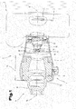
- Fig. 1 shows an inventive lens 1 in a connected position with an image recording device 2.
- the image recording device 2 may be, for example, a photo or film camera.
- the objective 1 is likewise shown in a connected position with an eyepiece 7 of a long-range optical device 4.
- An image 3 generated by the far-optical device 4 is generated on an image recording surface 5 after passing through the lens 1.
- the image recording surface can be formed, for example, by a photo film, an optoelectronic sensor or a purely other, optical sensor.
- the objective 1 has a housing 6 which can extend beyond the lens 13 closest to the far-optical device 4 in the direction of the eyepiece 7 of the long-range optical device 4.
- the housing 6 has a larger inner diameter 8 than the outer diameter 9 of the eyepiece housing 10.
- the housing 6 can also have only in an overlap region 19 a larger inner diameter 8 than the outer diameter 9 of the eyepiece housing 10.
- a connection of the housing 6 with the eyepiece 7 of the long-range optical device 4 is carried out detachably and can be realized for example by a fixing device 21.
- Both an exit pupil 11 of the long-range optical device 4, as well as an entrance pupil 12 of the objective 1 lie within the housing 6 of the objective 1.
- the objective 1 has at least one lens 13. However, a plurality of lenses 13 can also be provided.
- the optical axis 14 of the objective 1 is arranged parallel to the optical axis 15 of the eyepiece 7 of the long-range optical device 4 and parallel to the central axis 16 of the eyepiece housing.
- said axes 14, 15, 16 may form a single axis, preferably rectilinear.
- a slight misalignment of the optical axis 14 of the objective 1 less than 5 ° or a small radial distance between the optical axes of less than 3 mm can be compensated by an objective optics 35.
- the exit pupil 11 of the long-range optical device 4 as well as the entrance pupil 12 of the objective can lie on a single plane in a region 17 of the housing 6.
- the surfaces of the exit pupil 11 and the entrance pupil 12 overlap partially or completely, it is also advantageous if the exit pupil 11 and the entrance pupil 12 are arranged centrally to the optical axis 14 and in the longitudinal direction of the optical axis 14 at the same position.
- Fig. 2 shows a possible beam path through the eyepiece 7 of the long-range optical device 4 and through the lens 1 to the image recording surface 5 of the image recording device 2.
- a Aperture 18 can be arranged in or near a region 17, in which the exit pupil 11 and the entrance pupil 12 lie.
- the region 17 can be defined by two planes 46, 47, which are perpendicular to the optical axis 14. which may have a longitudinal distance 48 with respect to the optical axis 14 smaller than 5 mm, be limited.
- the diaphragm 18 may be formed, for example, by an aperture diaphragm.
- the objective 1 has a fixed focal length less than 100 mm, preferably between 40 and 30 mm.
- a fixed focal length of 30 mm between the objective optics 35 and the image recording surface 5 of the image recording apparatus 2 is advantageous.
- the exit pupil 11 of the long-range optical device 4 can be arranged between a diverging lens 26 and a converging lens 27. These lenses 26, 27 can be standard diffraction and collection lenses for long-range optical applications that are freely available on the market.
- the entrance pupil 12 of the objective 1 can also be arranged between the diverging lens 27 and the converging lens 28.
- the exit pupil 11 and the entrance pupil 12 can at least partially overlap one another or are minimally spaced apart in the longitudinal direction of the optical axis 14 of the objective 1, for example 0.001 to 5 mm, preferably 0.001 to 1 mm.
- the objective optics 35 may be formed by a diverging lens 26 on the side facing the far optical device, by a cemented member 36 which may be composed of a diverging and condenser lens and disposed on the side facing the image recording apparatus 2 and a converging lens 27 disposed therebetween ,
- the beams 37, 38, 39 of a beam 40 with edge beams 43, 4, which enter the diverging lens 26 of the objective optical system 35 in parallel, can form the exit pupil 11 and the entrance pupil 12 in the region 17.
- Edge regions of the radiation beam 40 can be shadowed, if desired, for example, by the diaphragm 18.
- the beams 37, 38, 39 of the beam 40 can be guided by the Sam-mellinse 27 and the cemented element 36, which may also be formed from commercially available composite diverging and converging lenses, to the image recording plane 5 of the image recording device 2, where a real image 3 of a far remote object 41 can be mapped.
- the exit pupil 11 of the long-range optical device 4 may be changed, for example, by the lens 13, which may be the diverging lens 26; in particular, its longitudinal position on the optical axis 15 may be shifted thereby and be closer or farther from the image recording surface 5.
- the exit pupil 11 of the long-range optical device 4 can also lie, for example, in front of the lens 13 or the objective optics 35, but within the housing 6.
- Fig. 3 is an interface 20 can be seen, with the housing 6 with the eyepiece housing 10 is detachably connected to the remote-optical device 4 can be releasably connected again.
- the connections of such an interface 20 may, for example, follow a fixing device 21, such as via a thread, via a clamping device, via a press fit, via a clamping screw or a quick-release device.
- the interface 20 can be connected to the eyepiece housing 10 of the eyepiece 7 of the long-range optical device 4 in such a way that optimum centering of the housing 6 of the objective 1 can be made possible.
- the interface 20 may be designed so that it can be connected to a plurality of different eyepiece housing types.
- the interface 20 can have devices which interact in particular with a centering device 33 and a longitudinal positioning device 34 on the housing 6.
- the interface 20 may, for example, be designed such that a stop surface 42 corresponding to an annular stop surface 29 of the housing 6 is arranged.
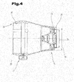
- Fig. 4 shows a longitudinal section through the lens 1.
- the lens for example, by a lens mount 22 with the image recording device releasably connected who the.
- a lens bayonet 22 can be releasably connectable to the housing via a thread 23, which preferably has a diameter 24 of 42 mm and a pitch 25 of 0.75 mm.
- other devices known from the prior art are also suitable for releasably connecting the objective bayonet to the housing. This can be thought of as clamping, latching or purely positive connections.
- the objective can be provided on its housing 6 with a centering device 33 and / or a longitudinal positioning device 34 and / or fixing device 21, which can also interact with corresponding counterparts on the eyepiece housing 10 or on the interface 20.
- the housing 6 may have on its end face 28 an annular stop surface 29, with the example, an alignment with the eyepiece housing 10 or the interface 20 can be made.
- the housing 6 can moreover be bell-shaped and have its smallest outer diameter 30 on an end region 31 facing the image recording apparatus 2.
- At least one interface for electronic data transmission 32 from and to the long-range optical device 4 and / or image recording device 2 can be arranged on the housing 6.
- Fig. 5 shows an exemplary beam path through the objective optical system 35.
- At least one point of intersection 45 of heavy beams 43, 44 of at least two beam bundles 40 can lie within the housing 6.
- the objective (1) may comprise at least one lens 13 with an optical axis 14.
- the intersection or points 45 may be arranged on a side of the lens 13 closest to the image recording surface 5, which side is opposite to the image recording surface 5.
- the objective optical system 35 may be constituted by a scattering lens 26 on the side facing the far optical apparatus, a cemented member 36 which may be composed of a dispersing lens and a condenser lens and disposed on the side facing the image recording apparatus 2 and a condensing lens 27 interposed therebetween be formed.
- the intersection (s) 45 may be disposed between the diverging lens 26 and the condenser lens 27.
- intersection (s) 45 of the heavy beams 43, 44 of at least two beam bundles 40 can, in an exemplary variant, lie within the housing 6 in a region 17 which is defined by two planes 46, 47 lying perpendicular to the optical axis 14 Longitudinal distance 48 relative to the optical axis 14 may have smaller 5 mm, may be limited.
- An aperture 18 may be arranged at least partially in this area 17.
Landscapes
- Physics & Mathematics (AREA)
- General Physics & Mathematics (AREA)
- Optics & Photonics (AREA)
- Astronomy & Astrophysics (AREA)
- Engineering & Computer Science (AREA)
- Multimedia (AREA)
- Signal Processing (AREA)
- Lenses (AREA)
Applications Claiming Priority (1)
| Application Number | Priority Date | Filing Date | Title |
|---|---|---|---|
| ATA669/2012A AT513009B1 (de) | 2012-06-11 | 2012-06-11 | Objektiv für ein Bildaufzeichnungsgerät |
Publications (2)
| Publication Number | Publication Date |
|---|---|
| EP2674811A2 true EP2674811A2 (fr) | 2013-12-18 |
| EP2674811A3 EP2674811A3 (fr) | 2014-01-15 |
Family
ID=48626274
Family Applications (1)
| Application Number | Title | Priority Date | Filing Date |
|---|---|---|---|
| EP20130170777 Withdrawn EP2674811A3 (fr) | 2012-06-11 | 2013-06-06 | Objectif pour un appareil d'enregistrement d'image |
Country Status (3)
| Country | Link |
|---|---|
| US (1) | US9883087B2 (fr) |
| EP (1) | EP2674811A3 (fr) |
| AT (1) | AT513009B1 (fr) |
Cited By (1)
| Publication number | Priority date | Publication date | Assignee | Title |
|---|---|---|---|---|
| WO2017071686A1 (fr) * | 2015-10-26 | 2017-05-04 | Leica Camera Ag | Adaptateur photographique |
Families Citing this family (3)
| Publication number | Priority date | Publication date | Assignee | Title |
|---|---|---|---|---|
| CN107167896B (zh) * | 2017-05-27 | 2023-04-28 | 福鼎市一雄光学仪器有限公司 | 高清水下视频摄像镜头 |
| JP7293791B2 (ja) * | 2019-03-26 | 2023-06-20 | 富士フイルムビジネスイノベーション株式会社 | 光学装置、画像読取装置、および画像形成装置 |
| CN115499574A (zh) * | 2022-11-17 | 2022-12-20 | 中央广播电视总台 | 无线传输控制系统和方法 |
Family Cites Families (22)
| Publication number | Priority date | Publication date | Assignee | Title |
|---|---|---|---|---|
| DE2848605A1 (de) * | 1978-11-09 | 1980-05-22 | Guido Georg Reinert | Weitfeld-adapter zur verbindung einer fernsehkamera mit einem mikroskop |
| JPS5689232A (en) * | 1979-12-24 | 1981-07-20 | Olympus Optical Co | Endoscope apparatus |
| JPS57129407A (en) * | 1981-02-03 | 1982-08-11 | Olympus Optical Co Ltd | Hard endoscope |
| US5053794A (en) | 1989-12-08 | 1991-10-01 | Benz William G | Universal adapter for attaching a camera to associated optical devices such as telescopes, microscopes and the like |
| DE4222417C2 (de) * | 1992-07-08 | 1994-06-23 | Swarovski & Co | Fernglas mit Zusatzinformation |
| DE4339397C2 (de) * | 1993-11-18 | 1996-03-07 | Swarovski Optik Kg | Zielfernrohr |
| US5583602A (en) * | 1994-04-07 | 1996-12-10 | Kyocera Corporation | Autofocus single-lens reflex camera |
| DE4438955C2 (de) * | 1994-10-31 | 1996-09-26 | Swarovski Optik Kg | Zielfernrohr |
| DE19504898C1 (de) * | 1995-02-14 | 1996-07-04 | Swarovski Optik Kg | Zielfernrohr |
| US6069651A (en) * | 1995-04-20 | 2000-05-30 | Olympus Optical Co., Ltd. | Imaging apparatus for endoscopes |
| JP3758801B2 (ja) * | 1997-04-16 | 2006-03-22 | ペンタックス株式会社 | 内視鏡対物レンズ系 |
| DE20005152U1 (de) | 2000-03-21 | 2000-06-29 | Kirchesch, Herbert, Dr.med., 50259 Pulheim | Adapter |
| JP2003029166A (ja) * | 2001-07-13 | 2003-01-29 | Shibuya Optical Co Ltd | 撮像用アダプタ |
| JP3970670B2 (ja) * | 2002-04-25 | 2007-09-05 | 株式会社 ニコンビジョン | カメラ取付用部品 |
| JP2005331923A (ja) * | 2004-04-23 | 2005-12-02 | Goko International Corporation | 光学装置及びそれを用いた撮影装置 |
| AT502229B1 (de) * | 2005-07-20 | 2007-05-15 | Swarovski Optik Kg | Fernoptische einrichtung |
| JP5036023B2 (ja) * | 2006-01-19 | 2012-09-26 | 株式会社 ニコンビジョン | 撮影装置および接眼レンズ |
| AT504400B1 (de) * | 2006-05-10 | 2008-09-15 | Swarovski Optik Kg | Zielfernrohr |
| JP5231162B2 (ja) * | 2008-10-22 | 2013-07-10 | 株式会社 ニコンビジョン | 光学機器 |
| JP5355474B2 (ja) * | 2010-03-31 | 2013-11-27 | キヤノン株式会社 | ズームレンズおよび光学機器 |
| JP5182357B2 (ja) * | 2010-09-09 | 2013-04-17 | 株式会社ニコン | 交換レンズおよびカメラボディ |
| DE102011000685B3 (de) * | 2011-02-11 | 2012-08-09 | Schmidt & Bender Gmbh & Co. Kg | Zielfernrohr mit Korrekturfeldlinse |
-
2012
- 2012-06-11 AT ATA669/2012A patent/AT513009B1/de active
-
2013
- 2013-06-06 EP EP20130170777 patent/EP2674811A3/fr not_active Withdrawn
- 2013-06-10 US US13/913,862 patent/US9883087B2/en active Active
Non-Patent Citations (1)
| Title |
|---|
| None * |
Cited By (1)
| Publication number | Priority date | Publication date | Assignee | Title |
|---|---|---|---|---|
| WO2017071686A1 (fr) * | 2015-10-26 | 2017-05-04 | Leica Camera Ag | Adaptateur photographique |
Also Published As
| Publication number | Publication date |
|---|---|
| AT513009A1 (de) | 2013-12-15 |
| AT513009B1 (de) | 2021-02-15 |
| EP2674811A3 (fr) | 2014-01-15 |
| US20130335626A1 (en) | 2013-12-19 |
| US9883087B2 (en) | 2018-01-30 |
Similar Documents
| Publication | Publication Date | Title |
|---|---|---|
| AT507542A1 (de) | Adapter für kamera und fernrohr | |
| DE102012108424A1 (de) | Optisches System mit einer GRIN-Optik und Vorrichtung mit zumindest zwei optischen Systemen | |
| DE69724603T2 (de) | Panoramisches periskop | |
| DE102017203673A1 (de) | Abbildungsobjektiv und Abbildungsvorrichtung | |
| DE102013105425B3 (de) | Fotografisches Weitwinkelobjektiv mit Innenfokussierung | |
| EP2519852A1 (fr) | Module caméra avec distance focale commutable | |
| WO2005083506A1 (fr) | Dispositif pour relier un objectif à une caméra | |
| DE102014119580A1 (de) | Digitales optisches Gerät mit Knickbrücke | |
| EP2674811A2 (fr) | Objectif pour un appareil d'enregistrement d'image | |
| DE102016220370A1 (de) | Adaptereinrichtung und Kameraobjektiv | |
| EP3059628A1 (fr) | Prolongateur de distances focales pour systemes d'imagerie telescopiques | |
| DE102012214303A1 (de) | Optisches System zur Abbildung eines Objekts | |
| AT502229B1 (de) | Fernoptische einrichtung | |
| EP0055209A2 (fr) | Dispositif pour faire tourner des faisceaux lumineux | |
| EP3633451B1 (fr) | Système de caméra à fixer notamment sur un équipement de visée optique | |
| DE60210807T2 (de) | Optisches Abbildungsverfahren | |
| DE102012020922A1 (de) | Laserscanner | |
| DE102018010386B4 (de) | Sichtsystem mit Driftausgleich sowie Verstelllinsensystem | |
| EP2894507A1 (fr) | Télescope avec système d'inversion à prismes | |
| DE102020204615A1 (de) | Schiefeebenemikroskop mit verbesserter Sammeleffizienz | |
| EP4302063B1 (fr) | Dispositif et procédé de mesure des propriétés d'imagerie d'un système optique | |
| DE102019132219B4 (de) | Verfahren zum Kalibrieren eines Systems, System, Durchflussmesszellenanordnung und Speichermedium | |
| DE212012000107U1 (de) | Endoskopobjektiv | |
| DE102019132218B4 (de) | Durchflussmesszelle | |
| DE3784964T2 (de) | Optische vorrichtung. |
Legal Events
| Date | Code | Title | Description |
|---|---|---|---|
| PUAL | Search report despatched |
Free format text: ORIGINAL CODE: 0009013 |
|
| PUAI | Public reference made under article 153(3) epc to a published international application that has entered the european phase |
Free format text: ORIGINAL CODE: 0009012 |
|
| AK | Designated contracting states |
Kind code of ref document: A2 Designated state(s): AL AT BE BG CH CY CZ DE DK EE ES FI FR GB GR HR HU IE IS IT LI LT LU LV MC MK MT NL NO PL PT RO RS SE SI SK SM TR |
|
| AX | Request for extension of the european patent |
Extension state: BA ME |
|
| AK | Designated contracting states |
Kind code of ref document: A3 Designated state(s): AL AT BE BG CH CY CZ DE DK EE ES FI FR GB GR HR HU IE IS IT LI LT LU LV MC MK MT NL NO PL PT RO RS SE SI SK SM TR |
|
| AX | Request for extension of the european patent |
Extension state: BA ME |
|
| RIC1 | Information provided on ipc code assigned before grant |
Ipc: G02B 17/02 20060101ALI20131211BHEP Ipc: G02B 21/36 20060101ALI20131211BHEP Ipc: G02B 15/12 20060101ALI20131211BHEP Ipc: G03B 17/48 20060101AFI20131211BHEP |
|
| 17P | Request for examination filed |
Effective date: 20140616 |
|
| RBV | Designated contracting states (corrected) |
Designated state(s): AL AT BE BG CH CY CZ DE DK EE ES FI FR GB GR HR HU IE IS IT LI LT LU LV MC MK MT NL NO PL PT RO RS SE SI SK SM TR |
|
| 17Q | First examination report despatched |
Effective date: 20180914 |
|
| RAP1 | Party data changed (applicant data changed or rights of an application transferred) |
Owner name: SWAROVSKI-OPTIK KG. |
|
| STAA | Information on the status of an ep patent application or granted ep patent |
Free format text: STATUS: THE APPLICATION IS DEEMED TO BE WITHDRAWN |
|
| 18D | Application deemed to be withdrawn |
Effective date: 20200806 |