EP2674894A2 - Erkennung von Fehlausrichtungen einer Kamera - Google Patents
Erkennung von Fehlausrichtungen einer Kamera Download PDFInfo
- Publication number
- EP2674894A2 EP2674894A2 EP13170425.6A EP13170425A EP2674894A2 EP 2674894 A2 EP2674894 A2 EP 2674894A2 EP 13170425 A EP13170425 A EP 13170425A EP 2674894 A2 EP2674894 A2 EP 2674894A2
- Authority
- EP
- European Patent Office
- Prior art keywords
- camera
- image
- test image
- location
- properly aligned
- Prior art date
- Legal status (The legal status is an assumption and is not a legal conclusion. Google has not performed a legal analysis and makes no representation as to the accuracy of the status listed.)
- Withdrawn
Links
Images


Classifications
-
- G—PHYSICS
- G06—COMPUTING OR CALCULATING; COUNTING
- G06T—IMAGE DATA PROCESSING OR GENERATION, IN GENERAL
- G06T7/00—Image analysis
- G06T7/70—Determining position or orientation of objects or cameras
- G06T7/73—Determining position or orientation of objects or cameras using feature-based methods
-
- G—PHYSICS
- G06—COMPUTING OR CALCULATING; COUNTING
- G06V—IMAGE OR VIDEO RECOGNITION OR UNDERSTANDING
- G06V20/00—Scenes; Scene-specific elements
- G06V20/50—Context or environment of the image
- G06V20/56—Context or environment of the image exterior to a vehicle by using sensors mounted on the vehicle
- G06V20/58—Recognition of moving objects or obstacles, e.g. vehicles or pedestrians; Recognition of traffic objects, e.g. traffic signs, traffic lights or roads
- G06V20/584—Recognition of moving objects or obstacles, e.g. vehicles or pedestrians; Recognition of traffic objects, e.g. traffic signs, traffic lights or roads of vehicle lights or traffic lights
-
- G—PHYSICS
- G06—COMPUTING OR CALCULATING; COUNTING
- G06T—IMAGE DATA PROCESSING OR GENERATION, IN GENERAL
- G06T2207/00—Indexing scheme for image analysis or image enhancement
- G06T2207/30—Subject of image; Context of image processing
- G06T2207/30232—Surveillance
-
- G—PHYSICS
- G06—COMPUTING OR CALCULATING; COUNTING
- G06T—IMAGE DATA PROCESSING OR GENERATION, IN GENERAL
- G06T2207/00—Indexing scheme for image analysis or image enhancement
- G06T2207/30—Subject of image; Context of image processing
- G06T2207/30236—Traffic on road, railway or crossing
-
- G—PHYSICS
- G06—COMPUTING OR CALCULATING; COUNTING
- G06T—IMAGE DATA PROCESSING OR GENERATION, IN GENERAL
- G06T2207/00—Indexing scheme for image analysis or image enhancement
- G06T2207/30—Subject of image; Context of image processing
- G06T2207/30244—Camera pose
Definitions
- the present inventive subject matter relates generally to the art of automated and/or unmanned cameras. Particular but not exclusive relevance is found in connection with red light and/or other traffic enforcement cameras. Accordingly, the present specification makes specific reference thereto. It is to be appreciated however that aspects of the present inventive subject matter are also equally amenable to other like applications.
- red light cameras are commonly aimed at or pointed in a direction of intersections having traffic going there through which is regulated by one or more traffic signals.
- traffic signals e.g., due to wind or other environmental conditions changing the alignment of the camera, unauthorized tampering with the camera's alignment, accidental misalignment during installation and/or maintenance of the camera, etc.
- objects of interest e.g., such as vehicles, drivers and/or license plates
- objects of interest e.g., such as vehicles, drivers and/or license plates
- accurate visualization and/or identification of such objects in captured images are often important for law enforcement purposes and/or the issuing of traffic citations.
- Camera misalignment results in the camera not being aimed or pointed in a desired direction.
- one or more objects of interest otherwise sought to be captured in an image obtained by the camera may not be in the camera's field-of view (FoV) or may not be sufficiently visualized and/or readily identifiable in the image. Accordingly, law enforcement or other actions reliant on accurate visualization and/or identification of one or more target objects in a captured image may be frustrated.
- some more advance camera systems may be triggered to capture an image in response to events occurring in a scene observed by the camera, e.g., such as the detection of a vehicle or vehicle movement within the scene. Where such an event is not observed by a misaligned camera, the camera may not capture an otherwise desired image because the event was not detected.
- operators of automated/unattended cameras such as those mentioned above relied on human labor-intensive practices to monitor, check and/or verify proper camera alignment.
- an operator may periodically or intermittently conduct a manual review of images obtained from a camera and visually inspect them for proper framing.
- Such an operator may commonly be assigned a significant number of cameras to check on a fairly frequent basis. Accordingly, such a process can be repetitive and prone to human oversight and/or error.
- a maintenance technician may be assigned to manually inspect camera installations in the field at periodic or intermittent intervals. Again, this is a labor-intensive process prone to human oversight and/or error.
- a new and/or improved method, system and/or apparatus for monitoring, detecting and/or reporting misalignment of a camera is disclosed which addresses the above-referenced problem(s) and/or others.
- a method for detecting misalignment of a camera from a test image captured by the camera. The method includes: analyzing the test image to detect an object appearing in the test image; determining a location where the detected object appears in the test image; comparing the determined location with a reference location; and determining if the camera is one of properly aligned or misaligned based upon a result of said comparison.
- a camera system includes: a camera that obtains a test image; and an image processor.
- the image processor analyzes said test image to detect an object appearing in the test image; determines a location where the detected object appears in the test image; compares the determined location with a reference location; and determines if the camera is one of properly aligned or misaligned based upon a result of said comparison.
- FIGURE 1 is a diagrammatic illustration showing an exemplary camera system suitable for practicing aspects of the present inventive subject matter.
- FIGURE 2 is a diagrammatic illustration showing an exemplary training image usable for practicing aspects of the present inventive subject matter.
- FIGURE 3 is a flow chart illustrating an exemplary process for analyzing an image in accordance with aspects of the present inventive subject matter.
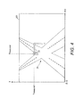
- FIGURE 4 is an illustration showing an exemplary image suitable for analysis in accordance with aspect of the present inventive subject matter.
- the present specification describes a method, process, apparatus and/or system for detecting misalignment of a camera, e.g., such as a red light or other traffic enforcement camera or other suitable automated or unmanned camera or the like.
- a camera e.g., such as a red light or other traffic enforcement camera or other suitable automated or unmanned camera or the like.
- the described method, process, apparatus and/or system analyzes images obtained by a camera to automatically detect one or more elements or objects appearing in the captured image.
- the elements or objects detected in the analyzed image are generally static and/or substantially immobile in nature, e.g., at least relative to the camera.
- Camera misalignment is then determined by comparing the locations where the detected elements/objects appear in the capture image to known or reference locations where the elements/objects should appear when the camera is properly aligned.
- the substantially static scene elements or objects detected may include without limitation: a red or other light of a traffic signal; a stop sign or other traffic sign; a roadway lane marker or divider or the like; a tollbooth; etc.
- an automated and/or unattended camera system 10 includes a camera 12 for selectively capturing and/or obtaining an image of a scene 20 within the camera's FoV.
- the camera 12 may be a digital camera and may be either a still picture camera or a video camera.
- a captured or otherwise obtained image from the camera 12 it is intended to mean an image from a picture camera or a still frame from a video camera.
- the camera 12 is generally aimed at and/or pointed in the direction of the scene 20 which contains at least one element or object 22 that is generally static and/or substantially immobile, e.g., at least relative to a position of the camera 12.
- the scene 20 at which the camera 12 is aimed and/or pointed is a traffic intersection and the element or object 22 is a light (e.g., a red light) of a traffic signal.
- scenes may be the subject of interest (e.g., a toll collection site) and/or other generally static elements and/or objects may be employed (e.g., a tollbooth, a stop sign or other traffic sign, a roadway lane marker or divider, etc.).
- the system 10 further includes a computer 30 or the like that is remotely or otherwise in communication with the camera 12.
- the computer 30 obtains or otherwise receives and analyzes images captured by the camera 12 in order to automatically monitor, detect and/or report misalignment of the camera 12.
- the image obtained or received and analyzed by the computer 30 is a digital image, e.g., captured by a digital camera.
- the computer 30 may receive an analog feed which is in turn digitized to obtain a digital image for analysis.
- the computer 30 obtains or receives and analyzes essentially all the images captured by the camera 12.
- the computer 30 may obtain or receive and analyze a representative sample or other subset of the images captured by the camera 12 at periodic or intermittent intervals or otherwise chosen times.
- the images may be transmitted from the camera 12 to the computer 30 and/or analyzed in real time or near real time or in batches or otherwise.
- FIGURE 2 there is shown an exemplary training or reference image 100 of the scene 20 captured by the camera 12 while the camera is known to be properly aligned (e.g., at or near the time of installation).
- the element or object 22 appears in the image 100 at a given location which shall be taken and/or referred to as the reference location.
- the reference location may be defined by a set of respective coordinates, e.g., such as (X ref , Y ref ), or otherwise quantified. In this way, the reference location may be established using the reference image 100.
- the reference image 100 may be analyzed using a process or method (e.g., the same as or similar to the one described below with respect to FIGURE 3 ) to automatically detect the element/object 22 in the reference image 100 and/or to automatically determine the location where the element/object 22 appears in the reference image 100.
- the location thus determined may then be electronically stored or saved or otherwise established as the reference location.
- the reference location may established manually, e.g., by entry of known coordinates or the like defining where the element/object 22 should appear in an image captured by the camera 12 when it is properly aligned.
- FIGURE 3 there is shown a flow chart illustrating an exemplary method and/or process 300 by which obtained or captured images are analyzed, e.g., by the computer 30.
- FIGURE 4 shows an exemplary test image 200 captured by the camera 12 and that may be so analyzed.
- the test image was captured while the camera 12 was out of alignment or misaligned.
- the test image 200 captured by the camera 12 also includes generally the scene 20 and the element or object 22 therein.
- the test image 200 is analyzed, e.g., using the method and/or process 300, to automatically detect the element/object 22 in the test image 200 and determine a location where the detected element/object 22 appears in the test image 200.
- the determined location where the element/object 22 appears in the test image 200 may be defined by a set of respective coordinates, e.g., such as (X measured , Y measured ), or otherwise quantified.
- whether or not the camera 12 is in proper alignment or is misaligned is determined by comparing the measured location where the element/object 22 appears in the test image 200 to the reference location.
- the camera 12 is deemed to be properly aligned or in alignment. Otherwise, if the measured and reference locations substantially depart from one another or are sufficiently different (e.g., outside some given tolerance or threshold), then the camera 12 is deemed to be out of alignment or misaligned.
- an image is obtained.
- the image 200 may be captured by the camera 12 and transmitted to the computer 30 for analysis.
- the image 200 is analyzed to detect the element or object 22 therein.
- this analysis may include segmenting the image 200 and searching within a given image segment for the element or object 22 being detected.
- the searched segment may be an upper portion of the image 200, e.g., such as the top quarter.
- the search may be executed by scanning the pixels of the image to look for patches or collections of pixels or the like having parameters or values (e.g., color, intensity, size, shape, etc.) sufficiently matching characteristic and/or features of the element/object being sought.
- the image 200 or image segment can be searched for an essentially circular red patch or collection of pixels having a suitable size.
- a scale invariant feature transform SIFT may be used to extract, identify and/or detect features of the image 200 corresponding to the element/object 22 being sought.
- the location where the detected element or object 22 appears in the image 200 is determined and/or otherwise established as the measured location.
- the determined location where the detected element/object 22 appears in the test image 200 (nominally referred to herein as the measured location) may be defined by a set of respective coordinates, e.g., such as (X measured , Y measured ), or otherwise quantified.
- the measured and reference locations are compared.
- the X and Y coordinates of the respective locations may be compared.
- the camera 12 is deemed to be properly aligned or in alignment and the process 300 may end. Otherwise, if the measured and reference locations substantially depart from one another or are sufficiently different (e.g., outside some given tolerance or threshold), then the camera 12 is deemed to be out of alignment or misaligned and the process may continue to step 312.
- an absolute value of the difference between the measured and reference locations may be compared to a threshold.
- the camera 12 is deemed to be in alignment, otherwise if the absolute value of the difference is greater than or equal to (or optionally merely greater than) the threshold, then the camera 12 is deemed to be out of alignment.
- a suitable notification of the misalignment is provided.
- the computer 30 may provide such a notification by way of a visual indication, audible signal, display or sending of a suitable message, activation of a humanly perceivable alert or alarm, etc.
- the computer 30 may include a processor, e.g., embodied by a computing or other electronic data processing device, that is configured and/or otherwise provisioned to perform one or more of the tasks, steps, processes, analysis, methods and/or functions described herein.
- a processor e.g., embodied by a computing or other electronic data processing device, that is configured and/or otherwise provisioned to perform one or more of the tasks, steps, processes, analysis, methods and/or functions described herein.
- the computer 30 or other electronic data processing device employed in the system 10 may be provided, supplied and/or programmed with a suitable listing of code (e.g., such as source code, interpretive code, object code, directly executable code, and so forth) or other like instructions or software or firmware (e.g., such as an application to perform and/or administer the processing and/or image analysis described herein), such that when run and/or executed by the computer or other electronic data processing device one or more of the tasks, steps, processes, analysis, methods and/or functions described herein are completed or otherwise performed.
- code e.g., such as source code, interpretive code, object code, directly executable code, and so forth
- firmware e.g., such as an application to perform and/or administer the processing and/or image analysis described herein
- the listing of code or other like instructions or software or firmware is implemented as and/or recorded, stored, contained or included in and/or on a non-transitory computer and/or machine readable storage medium or media so as to be providable to and/or executable by the computer or other electronic data processing device.
- suitable storage mediums and/or media can include but are not limited to: floppy disks, flexible disks, hard disks, magnetic tape, or any other magnetic storage medium or media, CD-ROM, DVD, optical disks, or any other optical medium or media, a RAM, a ROM, a PROM, an EPROM, a FLASH-EPROM, or other memory or chip or cartridge, or any other tangible medium or media from which a computer or machine or electronic data processing device can read and use.
- non-transitory computer-readable and/or machine-readable mediums and/or media comprise all computer-readable and/or machine-readable mediums and/or media except for a transitory, propagating signal.
- any one or more of the particular tasks, steps, processes, analysis, methods, functions, elements and/or components described herein may be implemented on and/or embodiment in one or more general purpose computers, special purpose computer(s), a programmed microprocessor or microcontroller and peripheral integrated circuit elements, an ASIC or other integrated circuit, a digital signal processor, a hardwired electronic or logic circuit such as a discrete element circuit, a programmable logic device such as a PLD, PLA, FPGA, Graphical card CPU (GPU), or PAL, or the like.
- any device capable of implementing a finite state machine that is in turn capable of implementing the respective tasks, steps, processes, analysis, methods and/or functions described herein can be used.
Landscapes
- Engineering & Computer Science (AREA)
- Physics & Mathematics (AREA)
- General Physics & Mathematics (AREA)
- Theoretical Computer Science (AREA)
- Multimedia (AREA)
- Computer Vision & Pattern Recognition (AREA)
- Traffic Control Systems (AREA)
- Image Analysis (AREA)
- Length Measuring Devices By Optical Means (AREA)
- Image Processing (AREA)
- Testing, Inspecting, Measuring Of Stereoscopic Televisions And Televisions (AREA)
Applications Claiming Priority (1)
| Application Number | Priority Date | Filing Date | Title |
|---|---|---|---|
| US13/524,404 US20130335579A1 (en) | 2012-06-15 | 2012-06-15 | Detection of camera misalignment |
Publications (2)
| Publication Number | Publication Date |
|---|---|
| EP2674894A2 true EP2674894A2 (de) | 2013-12-18 |
| EP2674894A3 EP2674894A3 (de) | 2015-01-14 |
Family
ID=48740811
Family Applications (1)
| Application Number | Title | Priority Date | Filing Date |
|---|---|---|---|
| EP13170425.6A Withdrawn EP2674894A3 (de) | 2012-06-15 | 2013-06-04 | Erkennung von Fehlausrichtungen einer Kamera |
Country Status (3)
| Country | Link |
|---|---|
| US (1) | US20130335579A1 (de) |
| EP (1) | EP2674894A3 (de) |
| JP (1) | JP2014003599A (de) |
Cited By (1)
| Publication number | Priority date | Publication date | Assignee | Title |
|---|---|---|---|---|
| US9924160B1 (en) | 2016-09-22 | 2018-03-20 | Fluke Corporation | Imaging device with alignment analysis |
Families Citing this family (10)
| Publication number | Priority date | Publication date | Assignee | Title |
|---|---|---|---|---|
| US9060164B2 (en) * | 2012-09-12 | 2015-06-16 | Xerox Corporation | Intelligent use of scene and test pattern analyses for traffic camera diagnostics |
| US10373470B2 (en) | 2013-04-29 | 2019-08-06 | Intelliview Technologies, Inc. | Object detection |
| US10085001B2 (en) * | 2014-03-21 | 2018-09-25 | Omron Corporation | Method and apparatus for detecting and mitigating mechanical misalignments in an optical system |
| CA2847707C (en) * | 2014-03-28 | 2021-03-30 | Intelliview Technologies Inc. | Leak detection |
| US10943357B2 (en) | 2014-08-19 | 2021-03-09 | Intelliview Technologies Inc. | Video based indoor leak detection |
| CA2992080C (en) * | 2015-07-13 | 2020-01-28 | Nissan Motor Co., Ltd. | Traffic light recognition device and traffic light recognition method |
| CN108961798B (zh) * | 2018-08-10 | 2021-05-18 | 长安大学 | 无人车交通信号灯自主感知能力测试系统及测试方法 |
| US10664997B1 (en) | 2018-12-04 | 2020-05-26 | Almotive Kft. | Method, camera system, computer program product and computer-readable medium for camera misalignment detection |
| JP7368822B2 (ja) * | 2019-05-31 | 2023-10-25 | i-PRO株式会社 | カメラパラメータ設定システムおよびカメラパラメータ設定方法 |
| JP7579137B2 (ja) * | 2020-12-24 | 2024-11-07 | 京セラ株式会社 | 観察装置及び観察装置のキャリブレーション方法 |
Family Cites Families (8)
| Publication number | Priority date | Publication date | Assignee | Title |
|---|---|---|---|---|
| JP2004240931A (ja) * | 2003-02-05 | 2004-08-26 | Sony Corp | 画像照合装置、画像照合方法、およびプログラム |
| JP2007208513A (ja) * | 2006-01-31 | 2007-08-16 | Matsushita Electric Ind Co Ltd | 画像位置ずれ検出装置および画像位置ずれ検出方法 |
| US8489353B2 (en) * | 2009-01-13 | 2013-07-16 | GM Global Technology Operations LLC | Methods and systems for calibrating vehicle vision systems |
| RU2484531C2 (ru) * | 2009-01-22 | 2013-06-10 | Государственное научное учреждение центральный научно-исследовательский и опытно-конструкторский институт робототехники и технической кибернетики (ЦНИИ РТК) | Устройство обработки видеоинформации системы охранной сигнализации |
| CN102959599B (zh) * | 2009-12-22 | 2015-07-15 | 莱达科技股份有限公司 | 用于交通检测的主动3d监控系统 |
| US8553982B2 (en) * | 2009-12-23 | 2013-10-08 | Intel Corporation | Model-based play field registration |
| JP5561524B2 (ja) * | 2010-03-19 | 2014-07-30 | ソニー株式会社 | 画像処理装置および方法、並びにプログラム |
| US9628749B2 (en) * | 2011-12-20 | 2017-04-18 | International Business Machines Corporation | Pre-setting the foreground view of a photograph via a camera |
-
2012
- 2012-06-15 US US13/524,404 patent/US20130335579A1/en not_active Abandoned
-
2013
- 2013-05-24 JP JP2013109583A patent/JP2014003599A/ja active Pending
- 2013-06-04 EP EP13170425.6A patent/EP2674894A3/de not_active Withdrawn
Non-Patent Citations (1)
| Title |
|---|
| None |
Cited By (3)
| Publication number | Priority date | Publication date | Assignee | Title |
|---|---|---|---|---|
| US9924160B1 (en) | 2016-09-22 | 2018-03-20 | Fluke Corporation | Imaging device with alignment analysis |
| EP3300351A1 (de) * | 2016-09-22 | 2018-03-28 | Fluke Corporation | Abbildungsvorrichtung mit ausrichtungsanalyse |
| US10397565B2 (en) | 2016-09-22 | 2019-08-27 | Fluke Corporation | Imaging device with alignment analysis |
Also Published As
| Publication number | Publication date |
|---|---|
| US20130335579A1 (en) | 2013-12-19 |
| EP2674894A3 (de) | 2015-01-14 |
| JP2014003599A (ja) | 2014-01-09 |
Similar Documents
| Publication | Publication Date | Title |
|---|---|---|
| EP2674894A2 (de) | Erkennung von Fehlausrichtungen einer Kamera | |
| US9064317B2 (en) | Detection of near-field camera obstruction | |
| US9990376B2 (en) | Methods for identifying a vehicle from captured image data | |
| CN105448103B (zh) | 车辆套牌检测方法与系统 | |
| US9030559B2 (en) | Constrained parametric curve detection using clustering on Hough curves over a sequence of images | |
| US8284996B2 (en) | Multiple object speed tracking system | |
| US8605949B2 (en) | Vehicle-based imaging system function diagnosis and validation | |
| US9536165B2 (en) | Flash characterization for camera | |
| CN111325988A (zh) | 基于视频的实时闯红灯检测方法、装置、系统及存储介质 | |
| JP6044522B2 (ja) | 緩徐変化検出システム | |
| CN113505638B (zh) | 车流量的监测方法、监测装置及计算机可读存储介质 | |
| KR101381580B1 (ko) | 다양한 조명 환경에 강인한 영상 내 차량 위치 판단 방법 및 시스템 | |
| CN106919610A (zh) | 车联网数据处理方法、系统及服务器 | |
| CN112507902A (zh) | 交通标志异常检测方法、计算机设备及存储介质 | |
| US9256803B2 (en) | Automatic detection of persistent changes in naturally varying scenes | |
| CN112104838A (zh) | 图像分辨方法及其监控摄像机与监控摄像系统 | |
| Koch et al. | Improving pothole recognition through vision tracking for automated pavement assessment | |
| CN112016509B (zh) | 人员站位异常提醒方法及装置 | |
| CN116664582B (zh) | 一种基于神经视觉网络的路面检测方法及装置 | |
| JP2009140160A (ja) | 車両ナンバー読取装置 | |
| CN113870185B (zh) | 基于图像抓拍的图像处理方法、终端及存储介质 | |
| KR101926435B1 (ko) | 시간압축방식을 이용한 객체 추적 시스템 | |
| US20210142481A1 (en) | Method and System of Evaluating the Valid Analysis Region of a Specific Scene | |
| CN112949465A (zh) | 车辆连续变道识别方法、装置、设备及存储介质 | |
| JP2001014571A (ja) | 火災検出装置、火災検出システム及び火災検出方法 |
Legal Events
| Date | Code | Title | Description |
|---|---|---|---|
| PUAI | Public reference made under article 153(3) epc to a published international application that has entered the european phase |
Free format text: ORIGINAL CODE: 0009012 |
|
| AK | Designated contracting states |
Kind code of ref document: A2 Designated state(s): AL AT BE BG CH CY CZ DE DK EE ES FI FR GB GR HR HU IE IS IT LI LT LU LV MC MK MT NL NO PL PT RO RS SE SI SK SM TR |
|
| AX | Request for extension of the european patent |
Extension state: BA ME |
|
| PUAL | Search report despatched |
Free format text: ORIGINAL CODE: 0009013 |
|
| AK | Designated contracting states |
Kind code of ref document: A3 Designated state(s): AL AT BE BG CH CY CZ DE DK EE ES FI FR GB GR HR HU IE IS IT LI LT LU LV MC MK MT NL NO PL PT RO RS SE SI SK SM TR |
|
| AX | Request for extension of the european patent |
Extension state: BA ME |
|
| RIC1 | Information provided on ipc code assigned before grant |
Ipc: G06K 9/32 20060101ALI20141210BHEP Ipc: G06T 7/00 20060101AFI20141210BHEP |
|
| 17P | Request for examination filed |
Effective date: 20150714 |
|
| RBV | Designated contracting states (corrected) |
Designated state(s): AL AT BE BG CH CY CZ DE DK EE ES FI FR GB GR HR HU IE IS IT LI LT LU LV MC MK MT NL NO PL PT RO RS SE SI SK SM TR |
|
| 17Q | First examination report despatched |
Effective date: 20170329 |
|
| STAA | Information on the status of an ep patent application or granted ep patent |
Free format text: STATUS: THE APPLICATION IS DEEMED TO BE WITHDRAWN |
|
| 18D | Application deemed to be withdrawn |
Effective date: 20170809 |