EP2675144A1 - Procédé et appareil permettant d'effectuer une communication sans fil entre des terminaux - Google Patents
Procédé et appareil permettant d'effectuer une communication sans fil entre des terminaux Download PDFInfo
- Publication number
- EP2675144A1 EP2675144A1 EP13172229.0A EP13172229A EP2675144A1 EP 2675144 A1 EP2675144 A1 EP 2675144A1 EP 13172229 A EP13172229 A EP 13172229A EP 2675144 A1 EP2675144 A1 EP 2675144A1
- Authority
- EP
- European Patent Office
- Prior art keywords
- terminal
- neighboring terminal
- neighboring
- signal
- screen data
- Prior art date
- Legal status (The legal status is an assumption and is not a legal conclusion. Google has not performed a legal analysis and makes no representation as to the accuracy of the status listed.)
- Granted
Links
Images


Classifications
-
- G—PHYSICS
- G06—COMPUTING OR CALCULATING; COUNTING
- G06F—ELECTRIC DIGITAL DATA PROCESSING
- G06F3/00—Input arrangements for transferring data to be processed into a form capable of being handled by the computer; Output arrangements for transferring data from processing unit to output unit, e.g. interface arrangements
- G06F3/01—Input arrangements or combined input and output arrangements for interaction between user and computer
- G06F3/048—Interaction techniques based on graphical user interfaces [GUI]
- G06F3/0487—Interaction techniques based on graphical user interfaces [GUI] using specific features provided by the input device, e.g. functions controlled by the rotation of a mouse with dual sensing arrangements, or of the nature of the input device, e.g. tap gestures based on pressure sensed by a digitiser
- G06F3/0488—Interaction techniques based on graphical user interfaces [GUI] using specific features provided by the input device, e.g. functions controlled by the rotation of a mouse with dual sensing arrangements, or of the nature of the input device, e.g. tap gestures based on pressure sensed by a digitiser using a touch-screen or digitiser, e.g. input of commands through traced gestures
-
- G—PHYSICS
- G06—COMPUTING OR CALCULATING; COUNTING
- G06F—ELECTRIC DIGITAL DATA PROCESSING
- G06F3/00—Input arrangements for transferring data to be processed into a form capable of being handled by the computer; Output arrangements for transferring data from processing unit to output unit, e.g. interface arrangements
- G06F3/01—Input arrangements or combined input and output arrangements for interaction between user and computer
- G06F3/03—Arrangements for converting the position or the displacement of a member into a coded form
- G06F3/033—Pointing devices displaced or positioned by the user, e.g. mice, trackballs, pens or joysticks; Accessories therefor
- G06F3/038—Control and interface arrangements therefor, e.g. drivers or device-embedded control circuitry
- G06F3/0383—Signal control means within the pointing device
-
- G—PHYSICS
- G06—COMPUTING OR CALCULATING; COUNTING
- G06F—ELECTRIC DIGITAL DATA PROCESSING
- G06F3/00—Input arrangements for transferring data to be processed into a form capable of being handled by the computer; Output arrangements for transferring data from processing unit to output unit, e.g. interface arrangements
- G06F3/01—Input arrangements or combined input and output arrangements for interaction between user and computer
- G06F3/03—Arrangements for converting the position or the displacement of a member into a coded form
- G06F3/041—Digitisers, e.g. for touch screens or touch pads, characterised by the transducing means
-
- G—PHYSICS
- G06—COMPUTING OR CALCULATING; COUNTING
- G06F—ELECTRIC DIGITAL DATA PROCESSING
- G06F3/00—Input arrangements for transferring data to be processed into a form capable of being handled by the computer; Output arrangements for transferring data from processing unit to output unit, e.g. interface arrangements
- G06F3/01—Input arrangements or combined input and output arrangements for interaction between user and computer
- G06F3/048—Interaction techniques based on graphical user interfaces [GUI]
- G06F3/0484—Interaction techniques based on graphical user interfaces [GUI] for the control of specific functions or operations, e.g. selecting or manipulating an object, an image or a displayed text element, setting a parameter value or selecting a range
- G06F3/0486—Drag-and-drop
-
- H—ELECTRICITY
- H04—ELECTRIC COMMUNICATION TECHNIQUE
- H04B—TRANSMISSION
- H04B5/00—Near-field transmission systems, e.g. inductive or capacitive transmission systems
- H04B5/20—Near-field transmission systems, e.g. inductive or capacitive transmission systems characterised by the transmission technique; characterised by the transmission medium
- H04B5/24—Inductive coupling
-
- H—ELECTRICITY
- H04—ELECTRIC COMMUNICATION TECHNIQUE
- H04B—TRANSMISSION
- H04B7/00—Radio transmission systems, i.e. using radiation field
- H04B7/24—Radio transmission systems, i.e. using radiation field for communication between two or more posts
- H04B7/26—Radio transmission systems, i.e. using radiation field for communication between two or more posts at least one of which is mobile
- H04B7/2603—Arrangements for wireless physical layer control
-
- H—ELECTRICITY
- H04—ELECTRIC COMMUNICATION TECHNIQUE
- H04M—TELEPHONIC COMMUNICATION
- H04M1/00—Substation equipment, e.g. for use by subscribers
- H04M1/72—Mobile telephones; Cordless telephones, i.e. devices for establishing wireless links to base stations without route selection
- H04M1/724—User interfaces specially adapted for cordless or mobile telephones
- H04M1/72403—User interfaces specially adapted for cordless or mobile telephones with means for local support of applications that increase the functionality
- H04M1/72409—User interfaces specially adapted for cordless or mobile telephones with means for local support of applications that increase the functionality by interfacing with external accessories
- H04M1/72412—User interfaces specially adapted for cordless or mobile telephones with means for local support of applications that increase the functionality by interfacing with external accessories using two-way short-range wireless interfaces
-
- H—ELECTRICITY
- H04—ELECTRIC COMMUNICATION TECHNIQUE
- H04W—WIRELESS COMMUNICATION NETWORKS
- H04W4/00—Services specially adapted for wireless communication networks; Facilities therefor
- H04W4/80—Services using short range communication, e.g. near-field communication [NFC], radio-frequency identification [RFID] or low energy communication
-
- H—ELECTRICITY
- H04—ELECTRIC COMMUNICATION TECHNIQUE
- H04W—WIRELESS COMMUNICATION NETWORKS
- H04W68/00—User notification, e.g. alerting and paging, for incoming communication, change of service or the like
- H04W68/02—Arrangements for increasing efficiency of notification or paging channel
-
- H—ELECTRICITY
- H04—ELECTRIC COMMUNICATION TECHNIQUE
- H04W—WIRELESS COMMUNICATION NETWORKS
- H04W76/00—Connection management
- H04W76/10—Connection setup
- H04W76/14—Direct-mode setup
-
- H—ELECTRICITY
- H04—ELECTRIC COMMUNICATION TECHNIQUE
- H04W—WIRELESS COMMUNICATION NETWORKS
- H04W8/00—Network data management
- H04W8/005—Discovery of network devices, e.g. terminals
-
- G—PHYSICS
- G06—COMPUTING OR CALCULATING; COUNTING
- G06F—ELECTRIC DIGITAL DATA PROCESSING
- G06F2203/00—Indexing scheme relating to G06F3/00 - G06F3/048
- G06F2203/041—Indexing scheme relating to G06F3/041 - G06F3/045
- G06F2203/04104—Multi-touch detection in digitiser, i.e. details about the simultaneous detection of a plurality of touching locations, e.g. multiple fingers or pen and finger
Definitions
- the present invention relates generally to a method for performing wireless communication between terminals, and more particularly, to automatic pairing between terminals.
- Bluetooth is widely used as a short-range communication method among wireless communication methods.
- An authentication procedure for a connection between terminals is required to perform wireless communication using Bluetooth. The authentication procedure is performed through multiple steps.
- a main terminal searches for each neighboring terminal having a Bluetooth function.
- a user of the main terminal selects a desired neighboring terminal.
- the user In order to find the terminal that the user desires, the user must clearly recognize the name of the desired terminal.
- a message is displayed to the user that inquires whether the user desires for the main terminal to be connected to the selected terminal.
- the user presses an accept button the authentication procedure for wireless communication between the main terminal and the selected terminal is terminated.
- the user in order to perform wireless communication, the user must go through multiple steps. Also, in order to select the desired terminal, the user must be well-acquainted with an accurate name of the desired terminal.
- an aspect of the present invention provides a pairing method between terminals.
- a method for performing wireless communication between terminals, by a main terminal.
- An inquiry message is transmitted to a neighboring terminal.
- An inquiry response message is received from the neighboring terminal. It is determined whether the main terminal overlaps the neighboring terminal. When the main terminal overlaps the neighboring terminal, paging is automatically performed, without intervention of a user of the main terminal, and pairing between the main terminal and the neighboring terminal is established.
- a machine-readable storage medium for performing wireless communication between terminals and storing a program, which when executed implements the steps of: transmitting an inquiry message to a neighboring terminal; receiving an inquiry response message from the neighboring terminal; determining whether the main terminal overlaps the neighboring terminal; and when the main terminal overlaps the neighboring terminal, automatically performing paging, without intervention of a user of the main terminal, and establishing pairing between the main terminal and the neighboring terminal.
- an apparatus for performing wireless communication between terminals.
- the apparatus includes a communication unit for transmitting an inquiry message to a neighboring terminal, and receiving an inquiry response message from the neighboring terminal.
- the apparatus also includes a controller for determining whether the apparatus overlaps the neighboring terminal, and when the apparatus overlaps the neighboring terminal, automatically performing paging, without intervention of a user of the apparatus, and establishing pairing between the apparatus and the neighboring terminal.
- FIG. 1 is a block diagram illustrating a configuration of a communication system, according to an embodiment of the present invention.
- the communication system includes a first terminal 100 and a second terminal 10.
- the first terminal 100 has a configuration identical to that of the second terminal 10.
- the first terminal 100 may have a configuration different from that of the second terminal 10.
- a description will be made based on the first terminal 100.
- such a description may be applied to the second terminal 10.
- a description of the second terminal 10 may be applied to the first terminal 100.
- the first terminal 100 may be embodied as, for example, a smart phone, a mobile phone, a video game console, a television (TV), a display device, a head unit for a vehicle, a laptop computer, a tablet Personal Computer (PC), a Personal Media Player (PMP), a Personal Digital Assistant (PDA), an electronic paper, and the like.
- the term "terminal” may be replaced in use by a term, such as a portable terminal, a communication terminal, or a portable communication terminal.
- the first terminal 100 may communicate with the second terminal 10, or may perform a task in association with the second terminal 10.
- the first terminal 100 may transmit screen data to the second terminal 10, via a network or a direct connection, to the second terminal 10.
- the first terminal 100 may control the second terminal 10, or may operate according to the control of the second terminal 10. This control may be implemented in various schemes.
- the networks may be a Local Area Network (LAN), a Wireless Local Area Network (WLAN), a Wide Area Network (WAN), an Internet, and a Small Area Network (SAN).
- LAN Local Area Network
- WLAN Wireless Local Area Network
- WAN Wide Area Network
- Internet an Internet
- SAN Small Area Network
- the present invention is not limited to this configuration.
- the first terminal 100 includes a first user interface 110, a first memory 120, a first sensor unit 130, a first camera 140, a first communication unit 150, a first display unit 160, a first touch sensor controller 170, a first touch sensor 180, and a first controller 190.
- the first touch sensor controller 170 may be integrated into the first touch sensor 180 or the first controller 190. Specifically, functions of the first touch sensor controller 170 may be regarded as being performed by the first touch sensor 180 or the first controller 190.
- the first user interface 110 which is a means for receiving user input or notifying a user of information, may be embodied as, for example, a speaker, a microphone, multiple buttons, a vibration motor, a connector, and a keypad.
- cursor control such as, for example, a mouse, a trackball, a joystick or cursor direction keys, may be provided to the first user interface 110 in order to transmit and receive information to/from the first controller 190 and in order to control the movement of a cursor on a screen of the first display unit 160.
- embodiments of the present invention are not limited to this configuration.
- the speaker may output sounds corresponding to various signals (e.g., a wireless signal, a broadcast signal, a digital audio file, a digital moving image file, and photography) to the outside of the first terminal 100.
- the first speaker may output a sound corresponding to a function that the first terminal 100 performs.
- the first terminal 100 may include multiple first speakers. The one first speaker or multiple first speakers may be disposed at an appropriate position or appropriate positions of the first terminal 100.
- the microphone receives a voice or sound as input from the outside of the first terminal 100, and generates an electrical signal.
- the buttons may be formed on a front surface, a lateral surface or a rear surface of the first terminal 100, and may include, for example, a power/lock button, a volume button, a menu button, a home button, a back button, a search button, and the like.
- the vibration motor may convert an electrical signal into a mechanical vibration.
- the vibration motor of the first terminal 100 when the first terminal 100 in a vibration mode receives a voice call from another device, the vibration motor of the first terminal 100 operates.
- the first terminal 100 may include multiple vibration motors.
- the one vibration motor or multiple vibration motors may be mounted within the first terminal 100.
- the vibration motor may operate in response to a touch action of the user who touches a touch screen.
- a connector may be used as an interface for connecting the first terminal 100 to an external device or a power source.
- data stored in the first memory 120 of the first terminal 100 may be transmitted to the external device, or data may be received from the external device.
- power may be supplied by the power source or a battery may be charged.
- the keypad may receive key input from the user in order to control the first terminal 100.
- the keypad includes a physical keypad installed on the first terminal 100 or a virtual keypad displayed on the touch screen.
- the first display unit 160 may display an image based on an image signal which is input from the first controller 190, and simultaneously, may receive user input data (i.e., user input information) and may output the user input data to the first controller 190.
- the first display unit 160 may be embodied as a display unit such as, for example, a Liquid Crystal Display (LCD), an Organic Light Emitting Diode (OLED), or a Light Emitting Diode (LED), and a touch panel disposed below or above the display unit. The touch panel senses user input.
- LCD Liquid Crystal Display
- OLED Organic Light Emitting Diode
- LED Light Emitting Diode
- a user input means e.g., a finger or a stylus
- the touch panel When a user input means (e.g., a finger or a stylus) touches the surface (i.e., a screen) of the first display unit 160, the touch panel outputs a sensing signal (or touch sensing signal) having information on an input position (or input coordinates) and/or an input state (e.g., mouse down, mouse up, mouse movement, or the like).
- the user may touch various executable items displayed on a screen of the first display unit 160, thereby executing an application related to the item.
- the first display unit 160 is a means for receiving input from the user, and outputs screen data related to applications, such as, for example, a camera application, video communication application and an Internet application.
- the touch screen is described as an example of the first display unit 160, the first display unit 160 may be implemented only by a conventional display apparatus. In an embodiment of the present invention, the screen may show the whole or part of an image displayed by the first
- the first display unit 160 may provide the user with a graphical user interface matched to various services (e.g., telephone call, data transmission, broadcasting, and capturing of photographs and/or moving images).
- the first display unit 160 may transmit user input data matched to at least one touch, which is input to the graphical user interface, to the first controller 190.
- a touch is not limited to the touch of the user's body or the input means enabling a touch on the first display unit 160, but may include a non-contact touch (e.g., a detectable distance between the first display unit 160 and the user's body or the input means enabling a touch is less than or equal to 1 mm).
- the touch screen may be embodied as, for example, a resistive touch screen, a capacitive touch screen, an infrared touch screen, an acoustic wave touch screen, and/or the like.
- the first sensor unit 130 includes at least one sensor for detecting the state (e.g., location, bearing, direction, or movement) of the first terminal 100.
- the first sensor unit 130 may include a proximity sensor for detecting whether the user is close to the first terminal 100, and a motion sensor for detecting motions of the first terminal 100 (e.g., the rotation, acceleration, deceleration, and vibration of the first terminal 100).
- the motion sensor may include an acceleration sensor, a gravity sensor, a shock sensor, a GPS sensor, and a compass sensor.
- the first sensor unit 130 may detect the state of the first terminal 100, may generate a signal corresponding to the detection, and may transmit the generated signal to the first controller 190.
- the GPS sensor may receive a signal (e.g., a radio wave) from each of multiple GPS satellites in the Earth's orbit, and may calculate a location of the first terminal 100 by using a Time Of Arrival (TOA) from each of the GPS satellites to the first terminal 100.
- a signal e.g., a radio wave
- TOA Time Of Arrival
- the first memory 120 may store applications for various functions such as, for example, a video call function and a game function; databases related to images, user information, documents, fingerprint information/data, and a table of mapping a fingerprint to a function for providing a Graphical User Interface (GUI) related to the applications; background images (for example, a menu screen image and a standby screen image) or operating programs that are required to drive the first terminal 100; images captured by the camera; and the like.
- the first memory 120 is a machine-readable medium.
- the term "machine-readable medium" can be defined as a medium which provides data to the machine in order to enable the machine to perform a particular function.
- the machine-readable medium may be a storage medium.
- the first memory 120 may include a non-volatile medium and a volatile medium. All of these mediums must be of a type that may be detected by a physical instrument that causes instructions delivered by the mediums to be read into the machine.
- the machine-readable medium may be embodied as at least one of a floppy disk, a flexible disk, a hard disk, a magnetic tape, a Compact Disc Read-Only Memory (CD-ROM), an optical disk, a punch card, a paper tape, a RAM, a Programmable Read-Only Memory (PROM), an Erasable PROM (EPROM), and a flash-EPROM.
- a floppy disk a flexible disk
- a hard disk a magnetic tape
- CD-ROM Compact Disc Read-Only Memory
- EPROM Erasable PROM
- flash-EPROM a flash-EPROM
- the first communication unit 150 is provided in order to be directly connected to an external device, or in order to be connected to it via a network, and may be a wired or wireless communication unit.
- the first communication unit 150 transmits data from the first controller 190, the first memory 120, the first camera 140 or the like, by a wire or wirelessly. Otherwise, the first communication unit 150 receives, by a wire, data from an external communication line, or wirelessly receives data transmitted over the air, and delivers the received data to the first controller 190, or stores the received data in the first memory 120.
- the first communication unit 150 may include at least one of a mobile communication module, a wireless LAN module and a short-range communication module.
- Examples of the first communication units 150 may include an Integrated Services Digital Network (ISDN) card, a modem, a LAN card, an Infrared module, a Bluetooth module, a Zigbee module, and a wireless module.
- ISDN Integrated Services Digital Network
- the first communication unit 150 may be a module that supports optional applicable wireless communication protocol, such as, for example, Universal Mobile Telecommunications System (UMTS), Global System for Mobile communications (GSM), Code Division Multiple Access (CDMA), CDMA2000, World Interoperability for Microwave Access (WIMAX), Third Generation Long Term Evolution (3G LTE), Wireless Fidelity (Wi-fi) 802.11x, Infrared Data Association (IrDA), Zigbee, Near Field Communication (NFC), Radio-Frequency IDentification (RFID), Bluetooth, Ultra-WideBand (UWB), or the like.
- UMTS Universal Mobile Telecommunications System
- GSM Global System for Mobile communications
- CDMA Code Division Multiple Access
- WIMAX World Interoperability for Microwave Access
- Wireless Fidelity (Wi-fi) 802.11x Infrared Data Association (IrDA), Zigbee, Near Field Communication (NFC), Radio-Frequency IDentification
- the mobile communication module allows the first terminal 100 to be connected to an external device through mobile communication by using at least one antenna.
- the mobile communication module transmits and receives a wireless signal for the exchange of data, or unidirectional transmission or reception of data, such as a voice call, a video call, a Short Message Service (SMS)) or a Multimedia Messaging Service (MMS), to/from a mobile phone, a smart phone, a tablet PC or another device, which has a telephone number or a network address, which is input to the first terminal 100.
- SMS Short Message Service
- MMS Multimedia Messaging Service
- the wireless LAN module may be connected to the Internet at a place where a wireless Access Point (AP) is installed.
- the wireless LAN module supports a wireless LAN standard (e.g., IEEE 802.11x of the Institute of Electrical and Electronics Engineers (IEEE)).
- IEEE 802.11x of the Institute of Electrical and Electronics Engineers (IEEE)
- the short-range communication module enables the first terminal 100 to perform short-range wireless communication with an external device.
- the first camera 140 may include a lens system, a driving unit and an image sensor, and may further include a flash.
- the first camera 140 converts a light signal, which is input (or captured) through the lens system, into an electrical image signal or image data, and outputs the electrical image signal or image data.
- the user may capture a moving image or a still image through the first camera 140.
- the first camera 140 forms an optical image of the subject, and detects the formed optical image as an electrical signal.
- the lens system forms an image of the subject by causing light incident from the outside to converge.
- the lens system includes at least one lens, and lenses may be a convex lens, an aspheric lens, and the like.
- the lens system has symmetry with respect to an optical axis passing through the center of the lens system, and the optical axis is defined as a central axis.
- the image sensor detects an optical image formed by external light incident through the lens system, as an electrical image signal.
- the image sensor includes multiple pixels arranged in the structure of an M ⁇ N matrix, and the pixel may include a photo diode and at least one transistor.
- the pixel accumulates charges generated by incident light (i.e., an exposure process), and a voltage according to the accumulated charges represents the illuminance of the incident light (i.e., a process for outputting image data).
- image data which is output from the image sensor is formed by a set of voltages (i.e., pixel values) which are output from the pixels, and the image data represents one image (i.e., a still image).
- the image includes M ⁇ N pixels.
- the image sensors may include a Charge-Coupled Device (CCD) image sensor, a Complementary Metal-Oxide Semiconductor (CMOS) image sensor, and the like.
- CCD Charge-Coupled Device
- CMOS Complementary Metal-Oxide Semiconductor
- the driving unit drives the image sensor according to the control of the first controller 190. According to a control signal received from the first controller 190, the driving unit exposes all pixels of the image sensor or only within a region of interest among all the pixels, and causes image data output from the pixels, to be output to the first controller 190.
- the first controller 190 executes an application according to user input data, and the application performs a program operation according to the user input data.
- the user input includes input through the keypad, the touch screen or the like, or a camera-based input.
- the first controller 190 may include a bus for information exchange and a processor connected to the bus in order to process information.
- the first controller 190 may also include a second memory (e.g., a Random Access Memory (RAM)) connected to the bus in order to store information required by the processor.
- the second memory may be used to store temporary information required by the processor.
- the first terminal 100 may further include a Read Only Memory (ROM) connected to the bus in order to store static information required by the processor.
- ROM Read Only Memory
- the first controller 190 which is a Central Processing Unit (CPU), controls an overall operation of the first terminal 100, and serves to perform a wireless pairing method and a dual display method according to an embodiment of the present invention.
- the first controller 190 processes an image received from the first camera 140, or an image stored in the first memory 120, on a frame-by-frame basis, and outputs an image frame which is converted to meet the characteristics (for example, size, image quality and resolution) of the screen of the first display unit 160.
- CPU Central Processing Unit
- FIG. 2 is a diagram illustrating a touch sensor and a touch sensor controller, according to an embodiment of the present invention.
- the touch sensor 180 which is an Electromagnetic Resonance (EMR) type-touch sensor, includes first and second loop units 210 and 220, operates according to the control of the first touch sensor controller 170, and outputs the detected signals to the first touch sensor controller 170.
- the first loop unit 210 includes multiple first loops 212
- the second loop unit 220 includes multiple second loops 222.
- the first loop unit 210 and the second loop unit 220 may be disposed in directions such that the first loop unit 210 lies perpendicular to the second loop unit 220.
- the first loop unit 210 is longer in the y-axis direction than in the x-axis direction. Accordingly, the first loop unit 210 is used to detect an x-axis coordinate of a position of pen input (i.e., a position of user input or a touch position). Also, the first loop unit 210 is used to detect an x-axis coordinate of an overlap position of the first and second touch sensors 180 and 18.
- the second loop unit 220 is longer in the x-axis direction than in the y-axis direction. Accordingly, the second loop unit 220 is used to detect a y-axis coordinate of a position of pen input. Also, the second loop unit 220 is used to detect a y-axis coordinate of an overlap position of the first and second touch sensors 180 and 18.
- Each of the first and second loops 212 and 222 may output a first signal of a first frequency in the form of an electrical signal received from the first touch sensor controller 170, as a signal in the form of an electromagnetic wave. Also, each of the first and second loops 212 and 222 may detect a second signal of a second frequency in the form of an electromagnetic wave, which is output from an external pen, or a third signal of the first frequency in the form of an electromagnetic wave, which is output from the second touch sensor 18, as a signal in the form of an electrical signal. Each of the first and second loops 212 and 222 then outputs the detected signal in the form of an electrical signal to the first touch sensor controller 170.
- a pen existing around the first touch sensor 180 receives the first signal in the form of an electromagnetic wave which is output from the first touch sensor 180, generates a second signal in the form of an electromagnetic wave according to an operation of a resonant circuit, and outputs the generated second signal to the outside.
- the pen is described only as an example, and thus has no restrictions thereon when the pen corresponds to a means capable of outputting the second signal of the second frequency in response to the input of the first signal of the first frequency.
- a means may be commonly referred to as a user input means.
- the pen includes a resonant circuit in which the first touch sensor 180 of the EMR-type may sense a position of the pen and which includes coils and capacitors.
- FIG. 3 is a block diagram illustrating a detailed configuration of a first touch sensor controller, according to an embodiment of the present invention.
- the first touch sensor controller 170 includes a driving unit 320, a switching unit 310 and a signal processing unit 330.
- the first touch sensor controller 170 controls the first loop unit 210 to output the first signal to the outside, and controls the second loop unit 220 to output the second signal and the third signal to the signal processing unit 330.
- the switching unit 310 connects the multiple first loops 212 to the driving unit 320 in order, and thereby allows the multiple first loops 212 to sequentially output first signals to the outside.
- the switching unit 310 also connects the multiple second loops 222 to the signal processing unit 330 in order, and thereby allows the multiple second loops 222 to sequentially output the second signals or the third signals to the signal processing unit 330.
- the first touch sensor controller 170 controls the second loop unit 220 to output first signals to the outside, and controls the first loop unit 210 to output second signals to the signal processing unit 330.
- the switching unit 310 connects the multiple second loops 222 to the driving unit 320 in order, and thereby allows the multiple second loops 222 to sequentially output the first signals to the outside.
- the switching unit 310 also connects the multiple first loops 212 to the signal processing unit 330 in order, and thereby allows the multiple first loops 212 to sequentially output the second signals or third signals to the signal processing unit 330.
- the first and second cycles are alternately and continuously repeated.
- the driving unit 320 outputs the first signal of the first frequency to the switching unit 310.
- the first frequency is higher than the second frequency, and an Alternating Current (AC) current source may be used as the driving unit 320.
- AC Alternating Current
- FIG. 4 is a block diagram illustrating a detailed configuration of a signal processing unit, according to an embodiment of the present invention.
- the signal processing unit 330 includes a receiver 410, first and second filters 420 and 440, a pen input detector 430, and an overlap detector 450.
- the receiver 410 amplifies the second signals received from the switching unit 310, and outputs the amplified second signals.
- the first filter 420 filters frequencies of the second and third signals received from the receiver 410, and thereby outputs only the second signals of the second frequency to the pen input detector 430.
- the first filter 420 may be a band-pass filter for passing a low frequency band or a wavelength-selective filter for selectively passing only particular low frequency components.
- the second filter 440 filters frequencies of the second and third signals received from the receiver 410, and thereby outputs only the third signals of the first frequency to the overlap detector 450.
- the second filter 440 may be a band-pass filter for passing a high frequency band or a wavelength-selective filter for selectively passing only particular high frequency components.
- the pen input detector 430 detects a pair of second signals, each having a peak voltage value that is greater than or equal to a first threshold among the second signals, derives x-axis and y-axis coordinates of a position of pen input from the pair of second signals, and outputs the derived x-axis and y-axis coordinates to the first controller 190.
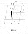
- FIGS. 5 and 6 are diagrams illustrating a method for detecting a position of pen input according to an embodiment of the present invention.
- each of the first and second loops 212 and 222 is schematically shown as one line.
- the second loop 222 (hereinafter, referred to as a "Y2 loop”) outputs a first signal to the outside.
- a pen 510 receives the first signal in the form of an electromagnetic wave, generates a second signal in the form of an electromagnetic wave according to an operation of the resonant circuit, and outputs the generated second signal to the outside.
- the multiple first loops 212 (hereinafter, referred to as "X1, X2 and X3 loops”) sequentially detect the second signals as signals in the form of an electrical signal.
- the pen input detector 430 derives an x-axis coordinate of a position of pen input, from a second signal having a peak voltage value that is greater than or equal to a first threshold, which is output from the X2 loop among the second signals.
- the first loop 212 (hereinafter, referred to as an "X2 loop") outputs a first signal to the outside.
- the pen 510 receives the first signal in the form of an electromagnetic wave, generates a second signal in the form of an electromagnetic wave according to an operation of the resonant circuit, and outputs the generated second signal to the outside.
- the multiple second loops 222 (hereinafter, referred to as "Y1, Y2 and Y3 loops”) sequentially detect the second signals as signals in the form of an electrical signal.
- the pen input detector 430 derives a y-axis coordinate of the position of the pen input, from a second signal having a peak voltage value that is greater than or equal to a first threshold, which is output from the Y2 loop among the second signals.
- the overlap detector 450 may determine only whether the first touch sensor 180 overlaps the second touch sensor 18, and may output only a result of the determination to the first controller 190. Otherwise, in a second mode, the overlap detector 450 may output x-axis and y-axis coordinates of an overlap position or area together with whether the first touch sensor 180 overlaps the second touch sensor 18, to the first controller 190. Whether the first touch sensor 180 overlaps the second touch sensor 18 may be known from whether an overlap position is output.
- the overlap detector 450 may output an overlap detection signal to the first controller 190.
- the overlap detector 450 detects at least a pair of third signals each having a peak value greater than or equal to the second threshold among the third signals, derives x-axis and y-axis coordinates of at least one overlap position from at least the pair of third signals, and outputs the derived x-axis and y-axis coordinates to the first controller 190.
- FIG. 7 is a diagram illustrating a method for detecting an overlap of first and second touch sensors, according to an embodiment of the present invention. For convenience of understanding, FIG. 7 illustrates only the disposition relation between the first and second touch sensors 180 and 18, according to an overlap of the first terminal 100 and the second terminal 10,
- the first terminal 100 and the second terminal 10 may know that they overlap each other according to the generation of an overlap detection signal from each of them. Also, the first terminal 100 and the second terminal 10 may detect an overlap area (a shaded area) 710.
- the second terminal 10 includes a second user interface 11, a second display unit 16, a second sensor unit 13, a second memory 12, a second communication unit 15, a second camera 14, a second touch sensor 18, a second touch sensor controller 17 and a second controller 19.
- a description of elements of the second terminal 10 is identical to that of corresponding elements of the first terminal 100, each of which has the same name as the corresponding element of the second terminal 10, except for an ordinal number.
- a wireless communication method and a dual display method are performed under the condition that one of the first terminal 100 and the second terminal 10 becomes a main terminal and the other becomes a sub-terminal.
- the first terminal 100 becomes a main terminal and the second terminal 10 becomes a sub-terminal.
- the wireless communication method is performed in a normal pairing mode or in an automatic pairing mode, according to whether an overlap is detected.
- FIG. 8 is a signal flow diagram illustrating a wireless pairing method according to a normal pairing mode, according to an embodiment of the present invention.
- functions performed by each of the first terminal 100 and the second terminal 10 are functions that each of the first controller 190 of the first terminal 100 and the second controller 19 of the second terminal 10 performs by using elements other than each of the first controller 190 and the second controller 19.
- step S810 the first terminal 100 transmits an inquiry message through the first communication unit 150 in order to identify whether other terminals exist around the first terminal 100. Specifcally, the first terminal 100 begins to search for a neighboring terminal while it performs an inquiry.
- step S820 the second terminal 10, which is in a discoverable mode, transmits an inquiry response message to the inquiry through the second communication unit 15.
- the discovered second terminal 10 includes various pieces of information possessed by itself, for example, a device address (ADDR), clock information (CLKN), and an error detection and correction signal (Bose-Chaudhuri-Hocquenghem code (BCH code)), in the inquiry response message, and transmits the inquiry response message including the various pieces of information, to the first terminal 100.
- ADDR device address
- CLKN clock information
- BCH code Bose-Chaudhuri-Hocquenghem code
- step S830 the first terminal 100, which has received an inquiry response message from each of the neighboring terminals including the second terminal 10, displays a list including indicators (e.g., addresses) for all of the discovered terminals, through the first display unit 160.
- indicators e.g., addresses
- step S840 the first terminal 100 determines whether a user selects a particular terminal from among the neighboring terminals displayed in the list, When the user selects the particular terminal from among the neighboring terminals displayed in the list, the first terminal 100 performs step S850, When the user does not select the particular terminal from among the neighboring terminals displayed in the list, the first terminal 100 maintains step S830.
- the user selects the particular terminal (in the present example, the second terminal 10) intended to be paired (or connected) with the first terminal 100, from among the discovered neighboring terminals displayed by the first display unit 160 of the first terminal 100.
- the first terminal 100 displays a window for inputting a password, on the screen of the first display unit 160.
- the first terminal 100 sequentially performs steps of paging (or synchronization) with respect to the second terminal 10 and pairing between itself and the second terminal 10, together with the second terminal 10.
- step S850 the first terminal 100 synchronizes a hopping sequence between itself and the second terminal 10 by using an address, clock information and the like.
- step S860 pairing between the first terminal 100 and the second terminal 10 is established.
- FIG. 9 is a signal flow diagram illustrating a wireless communication method according to an automatic pairing mode, according to an embodiment of the present invention.
- step S910 the first terminal 100 receives an overlap detection signal from the first touch sensor controller 170, and thereby detects that it overlaps the second terminal 10.
- step S920 the second terminal 10 receives an overlap detection signal from the second touch sensor controller 17, and thereby detects that it overlaps the first terminal 100.
- step S930 the first terminal 100 transmits an inquiry message in order to identify whether other terminals exist around the first terminal 100. Specifically, the first terminal 100 begins to search for a neighboring terminal while it performs an inquiry.
- the second terminal 10 which is in a discoverable mode, transmits an inquiry response message to the inquiry.
- the discovered second terminal 10 includes various pieces of information possessed by itself, for example, information such as a device address (ADDR), clock information (CLKN), and an error detection and correction signal (Bose-Chaudhuri-Hocquenghem code (BCH code)), and a recognition code (R-code), in an inquiry response message, and transmits the inquiry response message including the various pieces or information, to the first terminal 100.
- the recognition code is an optional code indicating that the second terminal 10 overlaps the first terminal 100.
- step S950 the first terminal 100, which has received the inquiry response message from the second terminal 10, identifies the recognition code included in the inquiry response message, does not wait for an inquiry response message from another terminal, and sequentially performs steps of paging (or synchronization) with respect to the second terminal 10 and pairing between itself and the second terminal 10, together with the second terminal 10.
- the recognition code may be transmitted to the first terminal 100 through a separate message other than the inquiry response message.
- step S960 the first terminal 100 synchronizes a hopping sequence between itself and the second terminal 10 by using an address, clock information and the like.
- step S970 pairing between the first terminal 100 and the second terminal 10 is established.
- FIG. 10 is a flowchart illustrating a method for performing wireless communication by a first terminal, according to an embodiment of the present invention.
- step S1010 the first terminal 100 transmits an inquiry message in order to search for neighboring terminals.
- step S1020 the first terminal 100 determines whether an inquiry response message is received. When the inquiry response message is received, the first terminal 100 proceeds to step S1030. When the inquiry response message is not received, the first terminal 100 periodically and repeatedly performs step S1020.
- step S1030 the first terminal 100, which has received the inquiry response message from the second terminal 10, determines whether a recognition code is included in the inquiry response message. When the recognition code is not included in the inquiry response message, the first terminal 100 proceeds to step S1040. When the recognition code is included in the inquiry response message, the first terminal 100 performs step S1070.
- step S1040 the first terminal 100 enters a standby state. Accordingly, the first terminal 100 collects various pieces of information, such as an ADDR and the like, from other terminals around the first terminal 100, generates a list of neighboring terminals based on a result of the collection, and displays the generated list on the first display unit 160.
- various pieces of information such as an ADDR and the like
- step S1050 the first terminal 100 determines whether a user selects a particular terminal from among the neighboring terminals displayed in the list.
- step S1060 the first terminal 100 performs paging with respect to the particular terminal (in the present example, the second terminal 10) selected in step S1050, and the first terminal continues to step S1090.
- the first terminal repeats the determination step of S1050.
- step S1070 the first terminal 100 acquires an ADDR included in the inquiry response message.
- step S1080 the first terminal 100 immediately performs paging with respect to the second terminal 10 having the acquired ADDR, and the first terminal continues to step S1090. Specifically, the first terminal 100 immediately performs paging with respect to the second terminal 10 without a standby state of receiving an inquiry response from each of the other neighboring terminals. Before the first terminal 100 performs paging with respect to the second terminal 10, it may display a window for inputting a password, on the first display unit 160.
- step S1090 the first terminal 100 determines whether pairing between it and the second terminal 10 is completed.
- the first terminal 100 proceeds to step S1095, and performs communication, such as data exchange, with the second terminal 10.
- the determination step S1090 is repeated.
- the first terminal 100 and the second terminal 10 sense an overlap of them. Accordingly, regardless of whether the first terminal 100 receives a recognition code, just before or after the overlap is sensed, the first terminal 100 may perform automatic pairing between it and the second terminal 10, which transmits an inquiry response message, together with the second terminal 10.
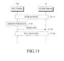
- FIG. 11 is a signal flow diagram illustrating a dual display method, according to an embodiment of the present invention.
- step S1110 wireless pairing between the first terminal 100 and the second terminal 10 is established.
- This wireless pairing may be established in the manner as described with reference to FIG. 8 or FIG. 9 .
- this wireless pairing may be established by using one of the wireless communication protocols, such as, for example, Wi-fi 802.11x, IrDA, Zigbee, NFC, RFID, and UWB.
- step S1120 which is a step of generating screen data
- the first terminal 100 recognizes an overlap of it and the second terminal 10, and generates first screen data and second screen data.
- the first screen data and the second screen data may be generated based on an overlap position.
- the first terminal 100 may generate screen data in a dual display scheme, which has previously been set or is set by the user's selection.
- the first screen data and the second screen data may represent two images, into which an image such as an application window or a home screen is divided, respectively.
- the first screen data may represent one application window
- the second screen data may represent information on an application that the second terminal 10 is to execute.
- the first screen data and the second screen data may represent two images, into which an image such as an application window or a home screen is horizontally divided, respectively.
- the first screen data and the second screen data may represent two images, into which an image such as an application window or a home screen is vertically divided, respectively.
- the first terminal 100 when the left or right part of the first terminal 100 overlaps the second terminal 10, the first terminal 100 may display one application window, and the second terminal 10 may vertically display a text input interface. Also, when the upper or lower part of the first terminal 100 overlaps the second terminal 10, the first terminal 100 may display one application window, and the second terminal 10 may horizontally display a text input interface.
- step S1130 which is a step of transmitting screen data
- the first terminal 100 transmits the second screen data to the second terminal 10.
- the generation and transmission of second screen data may be periodically performed.
- the generation and transmission of second screen data may be aperiodically performed when an event such as user input occurs.
- step S1140 which is a step of performing a dual display mode
- the first terminal 100 displays a first screen, which is based on the first screen data
- the second terminal 10 displays a second screen, which is based on the second screen data.
- FIG. 12 is a diagram illustrating a dual display method, according to an embodiment of the present invention.
- the first terminal 100 recognizes an overlap of it and the second terminal 10, and generates first screen data and second screen data.
- the first terminal 100 recognizes that a left part thereof overlaps the second terminal 10, horizontally divides one Internet application window into a first screen and a second screen, and transmits second screen data representing the second screen to the second terminal 10.
- the first display unit 160 of the first terminal 100 displays a first screen 1210 (i.e., one half of the Internet application window), which is based on the first screen data.
- the second display unit 16 of the second terminal 10 displays a second screen 1220 (i.e., the remaining half of the Internet application window), which is based on the second screen data.
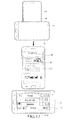
- FIG. 13 is a diagram illustrating a dual display method, according to another embodiment of the present invention.
- the first terminal 100 recognizes an overlap of it and the second terminal 10, and generates first screen data and second screen data.
- the first terminal 100 recognizes that a lower part thereof overlaps the second terminal 10, and generates first screen data representing one Internet application window and second screen data representing a text input interface.
- the first terminal 100 transmits the second screen data to the second terminal 10.
- the first display unit 160 of the first terminal 100 displays a first screen 1310, which is based on the first screen data.
- the second display unit 16 of the second terminal 10 displays a second screen 1320, which is based on the second screen data.
- the first terminal 100 displays the first screen 1310 representing the one Internet application window
- the second terminal 10 displays the second screen 1320 representing the text input interface.
- the fact that the first screen 1310 represents the one Internet application window implies that the first screen 1310 displays the undivided Internet application window, and does not imply that the entire first screen 1310 includes only the Internet application window, or that the entire Internet application window is displayed on one screen.
- the Internet application window may be displayed on a part of the first screen 1310, or a part of the Internet application window may be displayed.
- the first terminal 100 and the second terminal 10, as described above, may be referred to as a “main terminal” and a “neighboring terminal,” respectively, in order to distinguish between them.
- embodiments of the present invention may be implemented in the form of hardware, software, or a combination of hardware and software. Any such software may be stored in a volatile or non-volatile storage device such as a ROM, or in a memory such as a RAM, a memory chip, a memory device or a memory integrated circuit, or in a storage medium, such as a Compact Disc (CD), a Digital Versatile Disc (DVD), a magnetic disk or a magnetic tape, which is optically or magnetically recordable and simultaneously, is readable by a machine (e.g., a computer), regardless of whether the software can be deleted or rewritten.
- a volatile or non-volatile storage device such as a ROM
- a memory such as a RAM, a memory chip, a memory device or a memory integrated circuit
- a storage medium such as a Compact Disc (CD), a Digital Versatile Disc (DVD), a magnetic disk or a magnetic tape, which is optically or magnetically recordable and simultaneously,
- the memory which may be included in the terminal is an example of a non-transient machine-readable storage medium suitable for storing a program or programs including instructions for implementing the embodiments of the present invention. Accordingly, embodiments of the present invention include a program including codes for implementing an apparatus or a method, and a non-transitory storage medium which stores this program and is readable by a machine.
- the terminal may receive and store the program from a device for providing a program, which is connected to the terminal by a wire or wirelessly.
- the device for providing a program may include: a memory for storing a program including instructions which cause the terminal to perform a previously-set wireless communication method and/or a previously-set dual display method, information required for the wireless communication method and/or the dual display method; a communication unit for performing wired or wireless communication with the terminal, and a controller for performing a control operation so as to transmit the relevant program to the terminal, at a request from the terminal or automatically.
Landscapes
- Engineering & Computer Science (AREA)
- General Engineering & Computer Science (AREA)
- Theoretical Computer Science (AREA)
- Computer Networks & Wireless Communication (AREA)
- Signal Processing (AREA)
- Human Computer Interaction (AREA)
- Physics & Mathematics (AREA)
- General Physics & Mathematics (AREA)
- Databases & Information Systems (AREA)
- Telephone Function (AREA)
Applications Claiming Priority (1)
| Application Number | Priority Date | Filing Date | Title |
|---|---|---|---|
| KR1020120064456A KR101967670B1 (ko) | 2012-06-15 | 2012-06-15 | 단말들 간의 무선 통신 방법 |
Publications (2)
| Publication Number | Publication Date |
|---|---|
| EP2675144A1 true EP2675144A1 (fr) | 2013-12-18 |
| EP2675144B1 EP2675144B1 (fr) | 2018-03-07 |
Family
ID=48626337
Family Applications (1)
| Application Number | Title | Priority Date | Filing Date |
|---|---|---|---|
| EP13172229.0A Not-in-force EP2675144B1 (fr) | 2012-06-15 | 2013-06-17 | Procédé et appareil permettant d'effectuer une communication sans fil entre des terminaux |
Country Status (3)
| Country | Link |
|---|---|
| US (2) | US9537564B2 (fr) |
| EP (1) | EP2675144B1 (fr) |
| KR (1) | KR101967670B1 (fr) |
Cited By (1)
| Publication number | Priority date | Publication date | Assignee | Title |
|---|---|---|---|---|
| WO2016160114A1 (fr) * | 2015-03-27 | 2016-10-06 | Google Inc. | Fusion dynamique de plusieurs écrans en une fenêtre d'affichage |
Families Citing this family (12)
| Publication number | Priority date | Publication date | Assignee | Title |
|---|---|---|---|---|
| US8214645B2 (en) | 2009-04-08 | 2012-07-03 | Research In Motion Limited | Systems, devices, and methods for securely transmitting a security parameter to a computing device |
| US8171292B2 (en) * | 2009-04-08 | 2012-05-01 | Research In Motion Limited | Systems, devices, and methods for securely transmitting a security parameter to a computing device |
| KR101967670B1 (ko) * | 2012-06-15 | 2019-04-11 | 삼성전자주식회사 | 단말들 간의 무선 통신 방법 |
| KR20200108110A (ko) * | 2013-07-25 | 2020-09-16 | 인터디지털 씨이 페이튼트 홀딩스 | 객체들을 디스플레이하기 위한 방법 및 디바이스 |
| JP6327925B2 (ja) * | 2014-04-30 | 2018-05-23 | 株式会社ワコム | 位置検出装置 |
| US10613585B2 (en) * | 2014-06-19 | 2020-04-07 | Samsung Electronics Co., Ltd. | Transparent display apparatus, group play system using transparent display apparatus and performance methods thereof |
| DE102014220535A1 (de) * | 2014-10-09 | 2016-04-14 | Continental Automotive Gmbh | Fahrzeugmultimediaeinrichtung |
| US10101828B2 (en) * | 2016-08-11 | 2018-10-16 | Microsoft Technology Licensing, Llc | Pen wake up on screen detect |
| CN111083943B (zh) * | 2018-08-03 | 2023-11-24 | 深圳市汇顶科技股份有限公司 | 近距离无线通信连接方法、系统、主动笔及触摸屏 |
| CN114692105B (zh) * | 2020-12-31 | 2026-01-23 | 华为技术有限公司 | 一种密码重置的方法、装置和电子设备 |
| CN112905294B (zh) * | 2021-03-29 | 2022-02-22 | 腾讯科技(深圳)有限公司 | 数据处理方法、装置、设备以及介质 |
| US12554452B1 (en) * | 2024-09-30 | 2026-02-17 | Lenovo (United States) Inc. | Cursor movement across multiple displays |
Citations (2)
| Publication number | Priority date | Publication date | Assignee | Title |
|---|---|---|---|---|
| EP1237333A1 (fr) * | 2000-10-24 | 2002-09-04 | Sony Corporation | Procede de traitement d'informations et appareil correspondant dote d'une fonction de communication |
| US20040048570A1 (en) * | 2001-08-28 | 2004-03-11 | Haruo Oba | Information processing apparatus and method, and recording medium |
Family Cites Families (41)
| Publication number | Priority date | Publication date | Assignee | Title |
|---|---|---|---|---|
| JP2730018B2 (ja) | 1995-02-28 | 1998-03-25 | 株式会社ワコム | ディジタイザおよび位置検出方法 |
| EP2388770A1 (fr) | 2002-08-29 | 2011-11-23 | N-Trig Ltd. | Crayon digital |
| US8984440B2 (en) * | 2010-10-01 | 2015-03-17 | Z124 | Managing expose views in dual display communication devices |
| JP4266761B2 (ja) | 2003-09-25 | 2009-05-20 | 株式会社ワコム | 位置検出システム及び位置検出装置 |
| US7532196B2 (en) * | 2003-10-30 | 2009-05-12 | Microsoft Corporation | Distributed sensing techniques for mobile devices |
| US7453418B2 (en) * | 2003-12-19 | 2008-11-18 | Speechgear, Inc. | Display of visual data as a function of position of display device |
| WO2005096772A2 (fr) | 2004-04-01 | 2005-10-20 | Finepoint Innovations, Inc. | Systeme transducteur de surface sans fil |
| US7957768B2 (en) * | 2007-08-28 | 2011-06-07 | At&T Intellectual Property I, L.P. | Wireless communication device |
| KR100982282B1 (ko) * | 2008-09-19 | 2010-09-15 | 주식회사 애트랩 | 센서, 센서의 센싱 방법, 및 센서의 필터 |
| US20100167646A1 (en) * | 2008-12-30 | 2010-07-01 | Motorola, Inc. | Method and apparatus for device pairing |
| GB0908406D0 (en) * | 2009-05-15 | 2009-06-24 | Cambridge Silicon Radio Ltd | Proximity pairing |
| KR101711536B1 (ko) * | 2009-11-19 | 2017-03-02 | 엘지전자 주식회사 | 이동단말기 및 그의 착신 화면 표시 방법 |
| US20110143769A1 (en) * | 2009-12-16 | 2011-06-16 | Microsoft Corporation | Dual display mobile communication device |
| US9065532B2 (en) * | 2010-02-03 | 2015-06-23 | Google Inc. | Bump button |
| US8751970B2 (en) * | 2010-02-25 | 2014-06-10 | Microsoft Corporation | Multi-screen synchronous slide gesture |
| US9213480B2 (en) * | 2010-04-08 | 2015-12-15 | Nokia Technologies Oy | Method, apparatus and computer program product for joining the displays of multiple devices |
| JP2011248768A (ja) * | 2010-05-28 | 2011-12-08 | Sony Corp | 情報処理装置、情報処理システム及びプログラム |
| US9159298B2 (en) * | 2010-09-08 | 2015-10-13 | Lg Electronics Inc. | Terminal and contents sharing method for terminal |
| US9052760B2 (en) * | 2010-09-15 | 2015-06-09 | Lenovo (Singapore) Pte. Ltd. | Combining multiple slate displays into a larger display |
| KR101723642B1 (ko) * | 2011-01-31 | 2017-04-19 | 삼성전자주식회사 | 파노라마 이미지를 촬영하는 촬영 기기 및 그 파노라마 촬영 방법 |
| US20120214416A1 (en) * | 2011-02-23 | 2012-08-23 | Jonathan Douglas Kent | Methods and apparatuses for communication between devices |
| US8965286B2 (en) * | 2011-05-13 | 2015-02-24 | Nokia Corporation | Inquiry response event control |
| KR101797627B1 (ko) * | 2011-08-10 | 2017-11-15 | 엘지전자 주식회사 | 이동 단말기 및 그 제어방법 |
| US20130076653A1 (en) * | 2011-09-27 | 2013-03-28 | Mohammed Selim | Displaying of charging status on dual screen device |
| US9170607B2 (en) * | 2011-10-17 | 2015-10-27 | Nokia Technologies Oy | Method and apparatus for determining the presence of a device for executing operations |
| US20130106759A1 (en) * | 2011-10-27 | 2013-05-02 | Einar Fredriksen | Narrow-Band Touch Detection |
| US8797287B2 (en) * | 2011-10-28 | 2014-08-05 | Atmel Corporation | Selective scan of touch-sensitive area for passive or active touch or proximity input |
| KR101985275B1 (ko) * | 2012-02-02 | 2019-09-03 | 삼성전자주식회사 | 근거리 무선 통신 시스템 및 그 운용 방법 |
| US9197733B2 (en) * | 2012-02-21 | 2015-11-24 | Blackberry Limited | System and method for transferring data between electronic devices |
| US20130225078A1 (en) * | 2012-02-24 | 2013-08-29 | Karl-Anders Reinhold JOHANSSON | Method and apparatus for interconnected devices |
| US20130278540A1 (en) * | 2012-04-20 | 2013-10-24 | Esat Yilmaz | Inter Touch Sensor Communications |
| KR101959347B1 (ko) * | 2012-05-25 | 2019-03-18 | 삼성전자주식회사 | 복수의 통신 단말을 이용한 다중 디스플레이 방법, 기계로 읽을 수 있는 저장 매체 및 통신 단말 |
| KR101967670B1 (ko) * | 2012-06-15 | 2019-04-11 | 삼성전자주식회사 | 단말들 간의 무선 통신 방법 |
| KR101892959B1 (ko) * | 2012-08-22 | 2018-08-29 | 삼성전자주식회사 | 플렉서블 디스플레이 장치 및 플렉서블 디스플레이 장치의 제어 방법 |
| US8995911B2 (en) * | 2012-12-20 | 2015-03-31 | Nokia Technologies Oy | Apparatus and associated methods |
| KR102144553B1 (ko) * | 2013-08-30 | 2020-08-13 | 삼성전자주식회사 | 다중 디스플레이 방법, 저장 매체 및 전자 장치 |
| JP6214065B2 (ja) * | 2013-11-27 | 2017-10-18 | 株式会社ワコム | 電子機器 |
| US9538316B2 (en) * | 2014-07-25 | 2017-01-03 | Hannstar Display (Nanjing) Corporation | Smart monitor system and hand-held electronic device |
| US20160198499A1 (en) * | 2015-01-07 | 2016-07-07 | Samsung Electronics Co., Ltd. | Method of wirelessly connecting devices, and device thereof |
| JP6539133B2 (ja) * | 2015-07-09 | 2019-07-03 | クラリオン株式会社 | 車載端末およびプログラム |
| KR20170019995A (ko) * | 2015-08-13 | 2017-02-22 | 삼성전자주식회사 | 전자 장치와 탈부착 가능한 전자 장치를 동작시키는 방법 및 장치 |
-
2012
- 2012-06-15 KR KR1020120064456A patent/KR101967670B1/ko active Active
-
2013
- 2013-06-17 US US13/919,430 patent/US9537564B2/en active Active
- 2013-06-17 EP EP13172229.0A patent/EP2675144B1/fr not_active Not-in-force
-
2016
- 2016-12-29 US US15/394,077 patent/US10098171B2/en not_active Expired - Fee Related
Patent Citations (2)
| Publication number | Priority date | Publication date | Assignee | Title |
|---|---|---|---|---|
| EP1237333A1 (fr) * | 2000-10-24 | 2002-09-04 | Sony Corporation | Procede de traitement d'informations et appareil correspondant dote d'une fonction de communication |
| US20040048570A1 (en) * | 2001-08-28 | 2004-03-11 | Haruo Oba | Information processing apparatus and method, and recording medium |
Cited By (2)
| Publication number | Priority date | Publication date | Assignee | Title |
|---|---|---|---|---|
| WO2016160114A1 (fr) * | 2015-03-27 | 2016-10-06 | Google Inc. | Fusion dynamique de plusieurs écrans en une fenêtre d'affichage |
| US9965155B2 (en) | 2015-03-27 | 2018-05-08 | Google Llc | Dynamically merging multiple screens into one view port |
Also Published As
| Publication number | Publication date |
|---|---|
| KR20130141224A (ko) | 2013-12-26 |
| US20170111949A1 (en) | 2017-04-20 |
| US20130337747A1 (en) | 2013-12-19 |
| US10098171B2 (en) | 2018-10-09 |
| US9537564B2 (en) | 2017-01-03 |
| KR101967670B1 (ko) | 2019-04-11 |
| EP2675144B1 (fr) | 2018-03-07 |
Similar Documents
| Publication | Publication Date | Title |
|---|---|---|
| EP2675144B1 (fr) | Procédé et appareil permettant d'effectuer une communication sans fil entre des terminaux | |
| AU2013264497B2 (en) | Multiple display method with multiple communication terminals, machine-readable storage medium and communication terminal | |
| US10123366B2 (en) | Wireless connection method, machine-readable storage medium and electronic device using out-of-band channel | |
| CN106055300B (zh) | 用于控制声音输出的方法及其电子设备 | |
| JP6560763B2 (ja) | 指紋認識方法、指紋認識装置、プログラム及び記録媒体 | |
| US20170005826A1 (en) | Notification apparatus and object position notification method thereof | |
| JP2017537414A (ja) | 指紋認証方法及びその装置、プログラム及び記録媒体 | |
| US11375504B2 (en) | Method for indicating time-domain information of common control resource set of remaining minimum system information | |
| JP2017502622A (ja) | 無線装置リストの表示方法及びその表示装置、無線装置及びそのブロードキャストの方法、プログラム及び記録媒体 | |
| CN105611341B (zh) | 一种传输图像的方法、装置及系统 | |
| JP2012039282A (ja) | 電子機器、その情報表示プログラム及びその情報表示方法 | |
| US9867010B2 (en) | Method, electronic device, and computer readable recording medium for providing location based services | |
| US10013949B2 (en) | Terminal device | |
| CN105791558A (zh) | 移动终端及其控制终端设备的方法 | |
| US9544415B2 (en) | Mobile electronic device, position checking method, position checking program, and position checking system | |
| KR20150106535A (ko) | 이동 단말기 및 이의 제어 방법 | |
| KR20140109651A (ko) | 메시지 처리 방법 및 이를 이용한 장치 | |
| JP7462659B2 (ja) | 情報表示方法および装置 | |
| KR20180031238A (ko) | 이동 단말기 및 그 제어방법 | |
| KR20180016883A (ko) | 디스플레이 장치 및 그와 연결되는 단말기 | |
| CN118972638A (zh) | 分享方法、装置、终端及存储介质 | |
| TW201710933A (zh) | 電子裝置之偵測註冊方法及系統,及相關電腦程式產品 | |
| KR20190083920A (ko) | 전자 장치 및 그 제어 방법 | |
| KR20150099288A (ko) | 디스플레이를 제어하는 전자 장치 및 방법 | |
| KR20170024362A (ko) | 이동 단말기 및 그 제어 방법 |
Legal Events
| Date | Code | Title | Description |
|---|---|---|---|
| PUAI | Public reference made under article 153(3) epc to a published international application that has entered the european phase |
Free format text: ORIGINAL CODE: 0009012 |
|
| AK | Designated contracting states |
Kind code of ref document: A1 Designated state(s): AL AT BE BG CH CY CZ DE DK EE ES FI FR GB GR HR HU IE IS IT LI LT LU LV MC MK MT NL NO PL PT RO RS SE SI SK SM TR |
|
| AX | Request for extension of the european patent |
Extension state: BA ME |
|
| 17P | Request for examination filed |
Effective date: 20140618 |
|
| RBV | Designated contracting states (corrected) |
Designated state(s): AL AT BE BG CH CY CZ DE DK EE ES FI FR GB GR HR HU IE IS IT LI LT LU LV MC MK MT NL NO PL PT RO RS SE SI SK SM TR |
|
| 17Q | First examination report despatched |
Effective date: 20170224 |
|
| GRAP | Despatch of communication of intention to grant a patent |
Free format text: ORIGINAL CODE: EPIDOSNIGR1 |
|
| RIC1 | Information provided on ipc code assigned before grant |
Ipc: G06F 3/0488 20130101ALI20170831BHEP Ipc: G06F 3/041 20060101ALI20170831BHEP Ipc: H04B 7/26 20060101ALI20170831BHEP Ipc: H04W 76/02 20090101ALI20170831BHEP Ipc: H04W 4/00 20090101ALI20170831BHEP Ipc: H04W 8/00 20090101ALI20170831BHEP Ipc: H04M 1/725 20060101AFI20170831BHEP Ipc: G06F 3/038 20130101ALI20170831BHEP Ipc: G06F 3/0486 20130101ALI20170831BHEP Ipc: H04B 5/00 20060101ALI20170831BHEP |
|
| INTG | Intention to grant announced |
Effective date: 20170922 |
|
| GRAS | Grant fee paid |
Free format text: ORIGINAL CODE: EPIDOSNIGR3 |
|
| GRAA | (expected) grant |
Free format text: ORIGINAL CODE: 0009210 |
|
| AK | Designated contracting states |
Kind code of ref document: B1 Designated state(s): AL AT BE BG CH CY CZ DE DK EE ES FI FR GB GR HR HU IE IS IT LI LT LU LV MC MK MT NL NO PL PT RO RS SE SI SK SM TR |
|
| REG | Reference to a national code |
Ref country code: GB Ref legal event code: FG4D |
|
| REG | Reference to a national code |
Ref country code: CH Ref legal event code: EP Ref country code: AT Ref legal event code: REF Ref document number: 977751 Country of ref document: AT Kind code of ref document: T Effective date: 20180315 |
|
| REG | Reference to a national code |
Ref country code: IE Ref legal event code: FG4D |
|
| REG | Reference to a national code |
Ref country code: DE Ref legal event code: R096 Ref document number: 602013033945 Country of ref document: DE |
|
| REG | Reference to a national code |
Ref country code: NL Ref legal event code: FP |
|
| REG | Reference to a national code |
Ref country code: LT Ref legal event code: MG4D |
|
| PG25 | Lapsed in a contracting state [announced via postgrant information from national office to epo] |
Ref country code: HR Free format text: LAPSE BECAUSE OF FAILURE TO SUBMIT A TRANSLATION OF THE DESCRIPTION OR TO PAY THE FEE WITHIN THE PRESCRIBED TIME-LIMIT Effective date: 20180307 Ref country code: LT Free format text: LAPSE BECAUSE OF FAILURE TO SUBMIT A TRANSLATION OF THE DESCRIPTION OR TO PAY THE FEE WITHIN THE PRESCRIBED TIME-LIMIT Effective date: 20180307 Ref country code: CY Free format text: LAPSE BECAUSE OF FAILURE TO SUBMIT A TRANSLATION OF THE DESCRIPTION OR TO PAY THE FEE WITHIN THE PRESCRIBED TIME-LIMIT Effective date: 20180307 Ref country code: FI Free format text: LAPSE BECAUSE OF FAILURE TO SUBMIT A TRANSLATION OF THE DESCRIPTION OR TO PAY THE FEE WITHIN THE PRESCRIBED TIME-LIMIT Effective date: 20180307 Ref country code: NO Free format text: LAPSE BECAUSE OF FAILURE TO SUBMIT A TRANSLATION OF THE DESCRIPTION OR TO PAY THE FEE WITHIN THE PRESCRIBED TIME-LIMIT Effective date: 20180607 Ref country code: ES Free format text: LAPSE BECAUSE OF FAILURE TO SUBMIT A TRANSLATION OF THE DESCRIPTION OR TO PAY THE FEE WITHIN THE PRESCRIBED TIME-LIMIT Effective date: 20180307 |
|
| REG | Reference to a national code |
Ref country code: AT Ref legal event code: MK05 Ref document number: 977751 Country of ref document: AT Kind code of ref document: T Effective date: 20180307 |
|
| PG25 | Lapsed in a contracting state [announced via postgrant information from national office to epo] |
Ref country code: SE Free format text: LAPSE BECAUSE OF FAILURE TO SUBMIT A TRANSLATION OF THE DESCRIPTION OR TO PAY THE FEE WITHIN THE PRESCRIBED TIME-LIMIT Effective date: 20180307 Ref country code: RS Free format text: LAPSE BECAUSE OF FAILURE TO SUBMIT A TRANSLATION OF THE DESCRIPTION OR TO PAY THE FEE WITHIN THE PRESCRIBED TIME-LIMIT Effective date: 20180307 Ref country code: LV Free format text: LAPSE BECAUSE OF FAILURE TO SUBMIT A TRANSLATION OF THE DESCRIPTION OR TO PAY THE FEE WITHIN THE PRESCRIBED TIME-LIMIT Effective date: 20180307 Ref country code: GR Free format text: LAPSE BECAUSE OF FAILURE TO SUBMIT A TRANSLATION OF THE DESCRIPTION OR TO PAY THE FEE WITHIN THE PRESCRIBED TIME-LIMIT Effective date: 20180608 Ref country code: BG Free format text: LAPSE BECAUSE OF FAILURE TO SUBMIT A TRANSLATION OF THE DESCRIPTION OR TO PAY THE FEE WITHIN THE PRESCRIBED TIME-LIMIT Effective date: 20180607 |
|
| PG25 | Lapsed in a contracting state [announced via postgrant information from national office to epo] |
Ref country code: AL Free format text: LAPSE BECAUSE OF FAILURE TO SUBMIT A TRANSLATION OF THE DESCRIPTION OR TO PAY THE FEE WITHIN THE PRESCRIBED TIME-LIMIT Effective date: 20180307 Ref country code: EE Free format text: LAPSE BECAUSE OF FAILURE TO SUBMIT A TRANSLATION OF THE DESCRIPTION OR TO PAY THE FEE WITHIN THE PRESCRIBED TIME-LIMIT Effective date: 20180307 Ref country code: IT Free format text: LAPSE BECAUSE OF FAILURE TO SUBMIT A TRANSLATION OF THE DESCRIPTION OR TO PAY THE FEE WITHIN THE PRESCRIBED TIME-LIMIT Effective date: 20180307 Ref country code: RO Free format text: LAPSE BECAUSE OF FAILURE TO SUBMIT A TRANSLATION OF THE DESCRIPTION OR TO PAY THE FEE WITHIN THE PRESCRIBED TIME-LIMIT Effective date: 20180307 Ref country code: PL Free format text: LAPSE BECAUSE OF FAILURE TO SUBMIT A TRANSLATION OF THE DESCRIPTION OR TO PAY THE FEE WITHIN THE PRESCRIBED TIME-LIMIT Effective date: 20180307 |
|
| PG25 | Lapsed in a contracting state [announced via postgrant information from national office to epo] |
Ref country code: SK Free format text: LAPSE BECAUSE OF FAILURE TO SUBMIT A TRANSLATION OF THE DESCRIPTION OR TO PAY THE FEE WITHIN THE PRESCRIBED TIME-LIMIT Effective date: 20180307 Ref country code: CZ Free format text: LAPSE BECAUSE OF FAILURE TO SUBMIT A TRANSLATION OF THE DESCRIPTION OR TO PAY THE FEE WITHIN THE PRESCRIBED TIME-LIMIT Effective date: 20180307 Ref country code: AT Free format text: LAPSE BECAUSE OF FAILURE TO SUBMIT A TRANSLATION OF THE DESCRIPTION OR TO PAY THE FEE WITHIN THE PRESCRIBED TIME-LIMIT Effective date: 20180307 Ref country code: SM Free format text: LAPSE BECAUSE OF FAILURE TO SUBMIT A TRANSLATION OF THE DESCRIPTION OR TO PAY THE FEE WITHIN THE PRESCRIBED TIME-LIMIT Effective date: 20180307 |
|
| REG | Reference to a national code |
Ref country code: DE Ref legal event code: R097 Ref document number: 602013033945 Country of ref document: DE |
|
| PG25 | Lapsed in a contracting state [announced via postgrant information from national office to epo] |
Ref country code: PT Free format text: LAPSE BECAUSE OF FAILURE TO SUBMIT A TRANSLATION OF THE DESCRIPTION OR TO PAY THE FEE WITHIN THE PRESCRIBED TIME-LIMIT Effective date: 20180709 |
|
| RIC2 | Information provided on ipc code assigned after grant |
Ipc: H04W 76/02 20181130ALI20170831BHEP Ipc: G06F 3/0486 20130101ALI20170831BHEP Ipc: G06F 3/0488 20130101ALI20170831BHEP Ipc: G06F 3/038 20130101ALI20170831BHEP Ipc: G06F 3/041 20060101ALI20170831BHEP Ipc: H04B 7/26 20060101ALI20170831BHEP Ipc: H04W 4/00 20180101ALI20170831BHEP Ipc: H04W 8/00 20090101ALI20170831BHEP Ipc: H04M 1/725 20060101AFI20170831BHEP Ipc: H04B 5/00 20060101ALI20170831BHEP |
|
| PLBE | No opposition filed within time limit |
Free format text: ORIGINAL CODE: 0009261 |
|
| STAA | Information on the status of an ep patent application or granted ep patent |
Free format text: STATUS: NO OPPOSITION FILED WITHIN TIME LIMIT |
|
| REG | Reference to a national code |
Ref country code: CH Ref legal event code: PK Free format text: BERICHTIGUNGEN |
|
| PG25 | Lapsed in a contracting state [announced via postgrant information from national office to epo] |
Ref country code: DK Free format text: LAPSE BECAUSE OF FAILURE TO SUBMIT A TRANSLATION OF THE DESCRIPTION OR TO PAY THE FEE WITHIN THE PRESCRIBED TIME-LIMIT Effective date: 20180307 |
|
| REG | Reference to a national code |
Ref country code: CH Ref legal event code: PK Free format text: BERICHTIGUNGEN Ref country code: CH Ref legal event code: PL |
|
| 26N | No opposition filed |
Effective date: 20181210 |
|
| RIC2 | Information provided on ipc code assigned after grant |
Ipc: H04M 1/725 20060101AFI20170831BHEP Ipc: G06F 3/038 20130101ALI20170831BHEP Ipc: H04B 5/00 20060101ALI20170831BHEP Ipc: G06F 3/0488 20130101ALI20170831BHEP Ipc: G06F 3/041 20060101ALI20170831BHEP Ipc: H04W 4/00 20180101ALI20170831BHEP Ipc: H04W 76/02 20090101ALI20170831BHEP Ipc: G06F 3/0486 20130101ALI20170831BHEP Ipc: H04B 7/26 20060101ALI20170831BHEP Ipc: H04W 8/00 20090101ALI20170831BHEP |
|
| PG25 | Lapsed in a contracting state [announced via postgrant information from national office to epo] |
Ref country code: SI Free format text: LAPSE BECAUSE OF FAILURE TO SUBMIT A TRANSLATION OF THE DESCRIPTION OR TO PAY THE FEE WITHIN THE PRESCRIBED TIME-LIMIT Effective date: 20180307 |
|
| REG | Reference to a national code |
Ref country code: BE Ref legal event code: MM Effective date: 20180630 |
|
| REG | Reference to a national code |
Ref country code: IE Ref legal event code: MM4A |
|
| PG25 | Lapsed in a contracting state [announced via postgrant information from national office to epo] |
Ref country code: MC Free format text: LAPSE BECAUSE OF FAILURE TO SUBMIT A TRANSLATION OF THE DESCRIPTION OR TO PAY THE FEE WITHIN THE PRESCRIBED TIME-LIMIT Effective date: 20180307 Ref country code: LU Free format text: LAPSE BECAUSE OF NON-PAYMENT OF DUE FEES Effective date: 20180617 |
|
| PG25 | Lapsed in a contracting state [announced via postgrant information from national office to epo] |
Ref country code: LI Free format text: LAPSE BECAUSE OF NON-PAYMENT OF DUE FEES Effective date: 20180630 Ref country code: CH Free format text: LAPSE BECAUSE OF NON-PAYMENT OF DUE FEES Effective date: 20180630 Ref country code: FR Free format text: LAPSE BECAUSE OF NON-PAYMENT OF DUE FEES Effective date: 20180630 Ref country code: IE Free format text: LAPSE BECAUSE OF NON-PAYMENT OF DUE FEES Effective date: 20180617 |
|
| PG25 | Lapsed in a contracting state [announced via postgrant information from national office to epo] |
Ref country code: BE Free format text: LAPSE BECAUSE OF NON-PAYMENT OF DUE FEES Effective date: 20180630 |
|
| PG25 | Lapsed in a contracting state [announced via postgrant information from national office to epo] |
Ref country code: MT Free format text: LAPSE BECAUSE OF NON-PAYMENT OF DUE FEES Effective date: 20180617 |
|
| PG25 | Lapsed in a contracting state [announced via postgrant information from national office to epo] |
Ref country code: TR Free format text: LAPSE BECAUSE OF FAILURE TO SUBMIT A TRANSLATION OF THE DESCRIPTION OR TO PAY THE FEE WITHIN THE PRESCRIBED TIME-LIMIT Effective date: 20180307 |
|
| PG25 | Lapsed in a contracting state [announced via postgrant information from national office to epo] |
Ref country code: HU Free format text: LAPSE BECAUSE OF FAILURE TO SUBMIT A TRANSLATION OF THE DESCRIPTION OR TO PAY THE FEE WITHIN THE PRESCRIBED TIME-LIMIT; INVALID AB INITIO Effective date: 20130617 |
|
| PG25 | Lapsed in a contracting state [announced via postgrant information from national office to epo] |
Ref country code: MK Free format text: LAPSE BECAUSE OF NON-PAYMENT OF DUE FEES Effective date: 20180307 |
|
| PG25 | Lapsed in a contracting state [announced via postgrant information from national office to epo] |
Ref country code: IS Free format text: LAPSE BECAUSE OF FAILURE TO SUBMIT A TRANSLATION OF THE DESCRIPTION OR TO PAY THE FEE WITHIN THE PRESCRIBED TIME-LIMIT Effective date: 20180707 |
|
| PGFP | Annual fee paid to national office [announced via postgrant information from national office to epo] |
Ref country code: DE Payment date: 20210520 Year of fee payment: 9 Ref country code: NL Payment date: 20210521 Year of fee payment: 9 |
|
| PGFP | Annual fee paid to national office [announced via postgrant information from national office to epo] |
Ref country code: GB Payment date: 20210524 Year of fee payment: 9 |
|
| REG | Reference to a national code |
Ref country code: DE Ref legal event code: R119 Ref document number: 602013033945 Country of ref document: DE |
|
| REG | Reference to a national code |
Ref country code: NL Ref legal event code: MM Effective date: 20220701 |
|
| GBPC | Gb: european patent ceased through non-payment of renewal fee |
Effective date: 20220617 |
|
| PG25 | Lapsed in a contracting state [announced via postgrant information from national office to epo] |
Ref country code: NL Free format text: LAPSE BECAUSE OF NON-PAYMENT OF DUE FEES Effective date: 20220701 |
|
| PG25 | Lapsed in a contracting state [announced via postgrant information from national office to epo] |
Ref country code: GB Free format text: LAPSE BECAUSE OF NON-PAYMENT OF DUE FEES Effective date: 20220617 Ref country code: DE Free format text: LAPSE BECAUSE OF NON-PAYMENT OF DUE FEES Effective date: 20230103 |