EP2675223A1 - Procédé de réglage de puissance et station de base - Google Patents
Procédé de réglage de puissance et station de base Download PDFInfo
- Publication number
- EP2675223A1 EP2675223A1 EP12768138.5A EP12768138A EP2675223A1 EP 2675223 A1 EP2675223 A1 EP 2675223A1 EP 12768138 A EP12768138 A EP 12768138A EP 2675223 A1 EP2675223 A1 EP 2675223A1
- Authority
- EP
- European Patent Office
- Prior art keywords
- cell
- base station
- power
- signal quality
- radio resources
- Prior art date
- Legal status (The legal status is an assumption and is not a legal conclusion. Google has not performed a legal analysis and makes no representation as to the accuracy of the status listed.)
- Withdrawn
Links
Images



Classifications
-
- H—ELECTRICITY
- H04—ELECTRIC COMMUNICATION TECHNIQUE
- H04W—WIRELESS COMMUNICATION NETWORKS
- H04W52/00—Power management, e.g. Transmission Power Control [TPC] or power classes
- H04W52/04—Transmission power control [TPC]
- H04W52/18—TPC being performed according to specific parameters
- H04W52/24—TPC being performed according to specific parameters using SIR [Signal to Interference Ratio] or other wireless path parameters
-
- H—ELECTRICITY
- H04—ELECTRIC COMMUNICATION TECHNIQUE
- H04W—WIRELESS COMMUNICATION NETWORKS
- H04W52/00—Power management, e.g. Transmission Power Control [TPC] or power classes
- H04W52/04—Transmission power control [TPC]
- H04W52/18—TPC being performed according to specific parameters
- H04W52/24—TPC being performed according to specific parameters using SIR [Signal to Interference Ratio] or other wireless path parameters
- H04W52/241—TPC being performed according to specific parameters using SIR [Signal to Interference Ratio] or other wireless path parameters taking into account channel quality metrics, e.g. SIR, SNR, CIR or Eb/lo
-
- H—ELECTRICITY
- H04—ELECTRIC COMMUNICATION TECHNIQUE
- H04W—WIRELESS COMMUNICATION NETWORKS
- H04W52/00—Power management, e.g. Transmission Power Control [TPC] or power classes
- H04W52/04—Transmission power control [TPC]
- H04W52/18—TPC being performed according to specific parameters
- H04W52/24—TPC being performed according to specific parameters using SIR [Signal to Interference Ratio] or other wireless path parameters
- H04W52/243—TPC being performed according to specific parameters using SIR [Signal to Interference Ratio] or other wireless path parameters taking into account interferences
- H04W52/244—Interferences in heterogeneous networks, e.g. among macro and femto or pico cells or other sector / system interference [OSI]
-
- H—ELECTRICITY
- H04—ELECTRIC COMMUNICATION TECHNIQUE
- H04W—WIRELESS COMMUNICATION NETWORKS
- H04W52/00—Power management, e.g. Transmission Power Control [TPC] or power classes
- H04W52/04—Transmission power control [TPC]
- H04W52/18—TPC being performed according to specific parameters
- H04W52/24—TPC being performed according to specific parameters using SIR [Signal to Interference Ratio] or other wireless path parameters
- H04W52/242—TPC being performed according to specific parameters using SIR [Signal to Interference Ratio] or other wireless path parameters taking into account path loss
-
- H—ELECTRICITY
- H04—ELECTRIC COMMUNICATION TECHNIQUE
- H04W—WIRELESS COMMUNICATION NETWORKS
- H04W52/00—Power management, e.g. Transmission Power Control [TPC] or power classes
- H04W52/04—Transmission power control [TPC]
- H04W52/18—TPC being performed according to specific parameters
- H04W52/24—TPC being performed according to specific parameters using SIR [Signal to Interference Ratio] or other wireless path parameters
- H04W52/245—TPC being performed according to specific parameters using SIR [Signal to Interference Ratio] or other wireless path parameters taking into account received signal strength
-
- H—ELECTRICITY
- H04—ELECTRIC COMMUNICATION TECHNIQUE
- H04W—WIRELESS COMMUNICATION NETWORKS
- H04W92/00—Interfaces specially adapted for wireless communication networks
- H04W92/16—Interfaces between hierarchically similar devices
- H04W92/20—Interfaces between hierarchically similar devices between access points
Definitions
- Embodiments of the present invention relate to the field of communication technologies, and in particular, to a power tuning method and a base station.
- the Third Generation Partnership Project adopts inter-cell interference coordination (Inter-Cell Interference Coordination, ICIC) interference coordination mechanism in the time domain.
- the inter-cell interference coordination mechanism by sending an almost blank subframe (Almost Blank Subframe, ABS) to a user equipment (User Equipment, UE), solves the problem of control channel interference when large and small base stations are mixed in deployment, in which case, no data is transmitted in the ABS, which means the ABS can only be an empty frame.
- ABS almost Blank Subframe
- UE User Equipment
- Embodiments of the present invention provide a power tuning method and a base station, in order to realize dynamic tuning of transmitted power of radio resources.
- An embodiment of the present invention provides a power tuning method, including:
- An embodiment of the present invention also provides a power tuning method, including:
- An embodiment of the present invention also provides a base station, including:
- An embodiment of the present invention also provides a base station, including:
- the embodiments of the present invention may realize dynamic tuning of transmitted power of radio resources and further reduce the waste of radio resources while reducing interference on neighboring cells.
- FIG. 1 is a flowchart of a power tuning method according to an embodiment of the present invention.
- a first cell controlled by a first base station and a second cell controlled by a second base station are neighboring cells and the first cell is a serving cell of a first user equipment (UE 1).
- UE 1 user equipment
- the first cell is a micro cell
- the first base station is described as a base station serving the micro cell
- the second cell is a macro cell
- the second cell is described as a neighboring macro cell of the micro cell
- the second base station is described as a base station serving the macro cell.
- the embodiment of the present invention is not limited to this.
- the power tuning method may include:
- the foregoing embodiment may realize dynamic tuning of transmitted power of radio resources and further reduce the waste of radio resources while reducing interference on neighboring cells.
- FIG. 2 is a flowchart of a power tuning method according to another embodiment of the present invention.
- a first cell controlled by a first base station and a second cell controlled by a second base station are neighboring cells and the first cell is a serving cell of a first user equipment (UE 1).
- UE 1 user equipment
- the first cell is a micro cell
- the first base station is described as a base station serving the micro cell
- the second cell is a macro cell
- the second cell is described as a neighboring macro cell of the micro cell
- the second base station is described as a base station serving the macro cell.
- the embodiment of the present invention is not limited to this.
- the power tuning method may include:
- the foregoing embodiment may realize dynamic tuning of transmitted power of radio resources and further reduce the waste of radio resources while reducing interference on neighboring cells.
- FIG. 3 is a flowchart of a power tuning method according to still another embodiment of the present invention.
- a first cell controlled by a first base station and a second cell controlled by a second base station are neighboring cells and the first cell is a serving cell of a first user equipment (UE 1).
- UE 1 user equipment
- the first cell is a micro cell
- the first base station is described as a base station serving the micro cell
- the second cell is a macro cell
- the second cell is described as a neighboring macro cell of the micro cell
- the second base station is described as a base station serving the macro cell.
- the embodiment of the present invention is not limited to this.
- the power tuning method may include:
- the two base stations send information through the Uu interface, and specifically, one base station sends information in the broadcast of a cell it controls and the other base station reads the broadcast to obtain the information, or the other base station receives the information reported by the UE after the UE reads the broadcast at the cell edge.
- the power tuning information is determined by the first base station according to a signal quality threshold and the obtained received power.
- the first base station determines the power tuning information of the second cell according to the obtained received power, signal quality threshold, and total power of received signals of UE 1 or total downlink power (P total ) received by the first base station.
- the total downlink power received by the first base station in the embodiment of the present invention is the total power of downlink signals transmitted by other base stations (such as the second base station) and received by the first base station.
- the power tuning information is determined by the first base station according to the signal quality threshold and the obtained signal quality.
- the first base station determines the power tuning information of the second cell according to the obtained signal quality, signal quality threshold, and total power of received signals of UE 1 or total downlink power (P total ) received by the first base station.
- the first base station may send the obtained received power or signal quality to the second base station, so that the second base station determines the power tuning information and tunes the transmitted power of the radio resources according to the power tuning information.
- the received power or signal quality obtained by the second base station may be sent to the second base station by the first base station through an X2, S1, or Uu interface or through an OSS.
- the power tuning information is determined by the second base station according to the obtained received power or signal quality.
- the power tuning information is determined by the second base station according to the obtained received power and the signal quality threshold, or determined by the second base station according to the obtained signal quality and the signal quality threshold.
- the signal quality threshold is a reference signal received quality (Reference Signal Received Quality, RSRQ) threshold
- the second base station determines the power tuning information according to the obtained received power, RSRQ threshold, total power of received signals of UE 1 or total downlink power (P total ) received by the first base station, and path loss from the second base station to UE 1
- the second base station determines the power tuning information according to the obtained signal quality, RSRQ threshold, total power of received signals of UE 1 or total downlink power (P total ) received by the first base station, and path loss from the second base station to UE 1.
- the second base station may determine the power tuning information according to the obtained received power, SINR threshold, total power of received signals of UE 1 or total downlink power (P total ) received by the first base station, and path loss from the second base station to UE 1, or the second base station determines the power tuning information according to the obtained signal quality, SINR threshold, total power of received signals of UE 1 or total downlink power (P total ) received by the first base station, and path loss from the second base station to UE 1.
- SINR Signal to interference plus noise ratio
- the signal quality threshold may be obtained by the first base station or the second base station in advance and may be obtained in multiple manners.
- the signal quality threshold may be configured by an operation support subsystem, or configured by an operator of the OSS or Operations, Administration and Maintenance (Operation Administration and Maintenance, OAM) system, or configured by the manufacturer of the base station.
- OAM Operations, Administration and Maintenance
- the signal quality threshold obtained by the first base station may be sent to the second base station by the first base station through an X2, S1, or Uu interface or through an OSS, and optionally, the first base station sends the signal quality threshold to the second base station together with the received power (or signal quality) obtained by the first base station, or the first base station sends the signal quality threshold to the second base station in a message without the received power (or signal quality) obtained by the first base station.
- the signal quality threshold obtained by the second base station may be sent to the first base station, which is not described herein.
- the first base station and/or the second base station may use a default signal quality threshold. The embodiment does not limit how the first base station or the second base station obtains the signal quality threshold.
- the power tuning information in the embodiment may be a target value of power tuning or a code indicating the target value.
- the power tuning information may be an amplitude of power tuning or a code indicating the amplitude.
- the amplitude of power tuning is an increase or decrease for power tuning.
- the power tuning information may be a grade of power tuning or a code indicating the grade, such as a high, middle, or low grade of power tuning.
- the power tuning information in the embodiment may be represented in other forms apart from the numeric value, code, and grade, provided that the receiver of the power tuning information can know the meaning definitely.
- the form of the power tuning information is not limited in the embodiment.
- the radio resources in the embodiment may be time domain resources (such as ABS), or frequency domain resources (such as carriers, including primary and secondary carriers), or time-frequency resources (such as beams).
- time domain resources such as ABS
- frequency domain resources such as carriers, including primary and secondary carriers
- time-frequency resources such as beams.
- the specific form of the radio resources is not limited in the embodiment.
- the first base station may send the power tuning information to the second base station after determining the power tuning information, so that the second base station tunes the transmitted power of the radio resources according to the power tuning information.
- the first base station may send all or a part of the parameters used to determine the power tuning information to the second base station, so that the second base station tunes the transmitted power of the radio resources according to the power tuning information.
- the embodiment of the present invention may realize dynamic tuning of transmitted power of radio resources and further reduce the waste of radio resources while reducing interference on neighboring cells, thereby increasing the utilization efficiency of resources.
- the power tuning method provided in the embodiment is applicable to a self-organizing network (Self-planning Organized Network, SON). It realizes automatic dynamic tuning of power, which is quick and convenient and saves the cost required by manual tuning of power.
- FIG. 4 is a flowchart of a power tuning method according to still another embodiment of the present invention, where, exemplarily, radio resources are ABS, a first base station is a base station serving a micro cell (a first cell), a second base station is a base station serving a macro cell (a second cell), and the macro cell is a neighboring cell of the micro cell.
- the power tuning method may include:
- the base station serving the micro cell and/or the second base station may obtain the signal quality threshold in multiple manners, which is not described herein. For details, reference may be made to the examples in the foregoing embodiment.
- the base station serving the micro cell may not send the obtained received power but determines the interference tolerance (represented by Rtolerance) of the micro cell according to a ratio of the obtained received power to the signal quality of the micro cell (for example, the received power obtained by the UE in the micro cell by measuring the micro cell), and sends a grade of power tuning to the base station serving the macro cell according to the Rtolerance. If Rtolerance is higher than the threshold THP_CIHigh, the grade of power tuning is high. If Rtolerance is lower than the threshold THP_CILow, the grade of power tuning is low.
- the interference tolerance represented by Rtolerance
- the base station serving the macro cell determines the power tuning information according to the grade of power tuning and tunes the transmitted power of the ABS according to the power tuning information. For example, the base station serving the macro cell finds that the high grade of power tuning corresponds to -3 dB in the list, and therefore can determine that the power tuning information is -3 dB and reduce the power by 3 dB. For another example, the base station serving the macro cell finds that the low grade of power tuning corresponds to a range from 3 dB to 7 dB in the list, and therefore can determine that the power tuning information is 5 dB and raise the power by 5 dB.
- the power tuning methods provided in the embodiments of the present invention may determine the power tuning information in the following manners. It should be noted that in the following description, exemplarily, the power tuning information is determined by the second base station.
- the first base station may adopt the same manner to determine the power tuning information, where the first base station obtains all parameter values needed to determine the power tuning information and determines the power tuning information according to equations. This is not described again hereinafter.
- the total received power is the total received power of UE 1.
- the signal quality threshold is an RSRQ threshold and the second base station determines the RSRQ on an ABS according to equation (1).
- the power tuning information determined by the second base station for the ABS transmitted power is P tolerance , it should be guaranteed that the RSRQ of the ABS is greater than the preset RSRQ threshold after the transmitted power is tuned. That is, it should be guaranteed that inequation (2) is established. In this case, the power tuning information needs to satisfy inequation (3).
- P tolerance obtained from inequation (3) is a range or includes multiple possible P tolerance values
- one value of P tolerance may be determined randomly or by other means as the power tuning information.
- RSRP serving represents the reference signal received power (RSRQ) of the first cell, which is the received power obtained by the first base station.
- P total represents the total power of received signals of the UE in the first cell (the foregoing UE 1 or UE 2) (for example, obtained by the first base station by performing measurement or receiving a measurement result reported by the UE).
- RSRQ target represents the RSRQ threshold.
- PL represents the path loss (Pathloss) from the second base station to the UE in the first cell.
- PL may be obtained in the following manner: First, one or more than one PL value corresponding to the location of the UE is determined according to equation (4), and if there are multiple PL values, one PL value is determined according to the multiple PL values. For example, any one or a mean value of the PL values is taken.
- PL Received power obtained by the first base station / Transmitted power of the second base station
- the determination of PL may be executed by the first base station, in which case, the first base station may first obtain the transmitted power information of the second base station from the second base station.
- the determination of PL may also be executed by the second base station, in which case, the first base station first sends the received power obtained by the first base station (such as the received power measured and reported by the UE) to the second base station.
- the transmitted power information of the second base station may be sent by the second base station to the first base station through an X2, S1, or Uu interface, or through an OSS.
- the received power obtained by the first base station may be sent by the first base station to the second base station through an X2, S1, or Uu interface, or through an OSS.
- the signal quality threshold is an SINR threshold and the second base station determines the SINR on the ABS according to equation (5).
- the power tuning information determined by the second base station for the ABS transmitted power is P tolerance
- the SINR is greater than the preset SINR threshold after the transmitted power is tuned. That is, it should be guaranteed that inequation (6) is established.
- the power tuning information needs to satisfy inequation (7).
- SINR P serving / P total - P serving P serving / P total - P serving + P tolerance x PL ⁇ SINR target P tolerance ⁇ P serving / SINR target - P total + P target / PL
- RSRP serving represents the reference signal received power (RSRQ) of the first cell, which is the received power obtained by the first base station.
- P total represents the total power of received signals of the UE in the first cell (the foregoing UE 1 or UE 2) (for example, obtained by the first base station by performing measurement or receiving a measurement result reported by the UE).
- SINR target represents the SINR threshold.
- PL represents the path loss from the second base station to the UE in the first cell. The manner of obtaining PL is described in the foregoing examples and is not described herein again.
- the signal quality threshold is a reference signal received power threshold (represented by TH) of the second cell controlled by the second base station, which is received by the UE in the first cell.
- the received power obtained by the second base station includes the reference signal received signal.
- a process in which the second base station determines the power tuning information according to the obtained received power and the signal quality threshold may be as follows: First, the second base station determines the path loss (represented by PL) from the second base station to the UE in the first cell according to the obtained reference signal received power and the reference signal transmitted power, for example, a ratio of the obtained reference signal received power to the reference signal transmitted power is used as the PL.
- the second base station may determine maximum transmitted power PMAX according to the reference signal received signal threshold TH provided by the first cell and the path loss PL from the second base station to the UE in the first cell, for example, the value of TH/PL is used as PMAX.
- the second base station determines the power tuning information (represented by P tolerance ) according to PMAX and previously used transmitted power (the transmitted power used at a time point is expressed as P0), for example, the difference between PMAX and P0 is used as P tolerance .
- the foregoing embodiment provides an optimized tuning mechanism for transmitting data in the ABS in low power mode. It reduces interference on a neighboring cell, reduces the waste of spectrum resources, and increases the spectrum efficiency by dynamically tuning the transmitted power of the ABS when data is transmitted in the ABS in low power mode. Further, the power tuning method is applicable to SONs, where automatic dynamic tuning of power is realized, which is quick and convenient and saves the cost required by manual tuning of power.
- radio resources are the ABS but the present invention is not limited to this.
- the power tuning method provided in the embodiment of the present invention is also applicable to scenarios of carrier aggregation) or beam forming.
- the radio resources are carriers or beams.
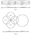
- FIG. 5 is a schematic diagram of carrier-aggregated cells provided in an embodiment of the present invention.
- the first cell includes three carriers, carrier 1, carrier 2, and carrier 3.
- the interference on the second cell may be regarded as coming from one carrier (for example, carrier 3).
- the power tuning of each carrier may be implemented by adopting the multiple methods and examples described in the foregoing embodiment, so that automatic dynamic tuning of power in an SON is realized.
- carrier 3 as an example, the parameter values related to the power tuning method provided in the foregoing embodiment, such as RSRP, RSRQ, or SINR, are no longer ABS measurement results but measurement results of carrier 3In the scenario shown in FIG. 5 , measurement should be performed respectively for carrier 1, carrier 2, and carrier 3 or measurement results thereof should be obtained respectively, so as to determine the power tuning information and implement power tuning.
- FIG. 6 is a schematic diagram of beam-formed cells according to an embodiment of the present invention. As shown in FIG. 6 , the first cell and the second cell are neighboring cells. Four beams constituted at time t and frequency f in the first cell are as follows:
- the second cell can know the time-frequency status of Beam configurations in the first cell in advance. After a UE at the edge of the second cell performs measurement on (tx, fx) to obtain measurement results such as the RSRP, RSRQ, and/or SINR, the base station serving the second cell can know, according to the early known time-frequency status of Beam configurations in the first cell, the Beam corresponding to the RSRP, RSRQ, or SINR measured by the UE at the edge of the second cell. Then, the methods and examples provided in the foregoing embodiment may be used to realize tuning of Beam power according to an automatic tuning mechanism in an SON.
- the program may be stored in a computer readable storage medium and when the program is executed, the steps in the methods of the embodiments are executed.
- the foregoing storage medium includes any medium that can store program codes, such as a ROM, a RAM, a magnetic disk, or a CD-ROM.
- FIG. 7 is a schematic diagram of a base station (the first base station hereinafter) according to an embodiment of the present invention, where the first base station can implement the actions executed by the first base station in the power tuning methods provided in the foregoing embodiments.
- the first base station may include:
- the first processor 71 may determine the power tuning information of the second cell according to the signal quality information of the radio resources of the second cell, the signal quality threshold, total power of received signals of a user equipment, and path loss from the second base station to the user equipment, where a serving cell of the user equipment is the first cell; or the first processor 71 may determine the power tuning information of the second cell according to the signal quality information of the radio resources of the second cell, the signal quality threshold, total downlink power received by the first base station, and path loss from the second base station to the user equipment, where a serving cell of the user equipment is the first cell.
- the path loss from the second base station to the user equipment is determined by the first processor 71 according to transmitted power information of the second base station and received power of the radio resources of the second cell, where the transmitted power information of the second base station is sent by the second base station to the first base station through an X2, S1, or Uu interface, or through an OSS; or the path loss from the second base station to the user equipment is determined by the second base station according to transmitted power information of the second base station and received power of the radio resources of the second cell, where the received power of the radio resources of the second cell is sent by the first base station to the second base station through an X2, S1, or Uu interface, or through an OSS.
- the signal quality information of the radio resources of the second cell includes the received power of the radio resources of the second cell or a measured value of signal quality of the radio resources of the second cell.
- the signal quality information of the radio resources of the second cell is a measurement result obtained by the first base station by measuring the second cell; or the signal quality information of the radio resources of the second cell is a measurement result sent by a user equipment to the first base station after the user equipment measures the second cell according to an instruction of the first base station, where a serving cell of the user equipment is the first cell.
- the signal quality threshold is a reference signal received power threshold, or a reference signal received quality threshold, or a signal to interference plus noise ratio threshold.
- the first processor 71 may determine the power tuning information of the second cell according to the signal quality threshold and a ratio of the signal quality information of the radio resources of the second cell to signal quality of the first cell; or the first processor 71 may, when the signal quality threshold is a reference signal received power threshold and the signal quality information is reference signal received power, determine the power tuning information of the second cell according to the reference signal received power threshold, the reference signal received power, reference signal transmitted power, and previously used transmitted power.
- the transmitter 72 may send the power tuning information of the second cell to the second base station through an X2, S1, or Uu interface or through an OSS.
- the power tuning information may include any one of the following items:
- the radio resource in the embodiment may include any one of almost blank subframes, carriers, and beams.
- the foregoing first base station may realize dynamic tuning of transmitted power of radio resources and further reduce the waste of radio resources while reducing interference on neighboring cells.
- FIG. 8 is a schematic diagram of a base station (the second base station hereinafter) according to an embodiment of the present invention, where the second base station can implement the actions executed by the second base station in the power tuning method provided in the foregoing embodiments.
- the second base station may include:
- the second processor 82 may determine the power tuning information of the second cell according to the signal quality information of the radio resources of the second cell, a signal quality threshold, total power of received signals of a user equipment, and path loss from the second base station to the user equipment, where a serving cell of the user equipment is the first cell; or the second processor 82 may determine the power tuning information of the second cell according to the signal quality information of the radio resources of the second cell, a signal quality threshold, total downlink power received by the first base station, and path loss from the second base station to the user equipment, where a serving cell of the user equipment is the first cell.
- the path loss from the second base station to the user equipment is determined by the first base station according to transmitted power information of the second base station and received power of the radio resources of the second cell, where the transmitted power information of the second base station is sent by the second base station to the first base station through an X2, S1, or Uu interface, or through an OSS; or the path loss from the second base station to the user equipment is determined by the second base station according to transmitted power information of the second base station and received power of the radio resources of the second cell, where the received power of the radio resources of the second cell is sent by the first base station to the second base station through an X2, S1, or Uu interface, or through an OSS.
- the signal quality information of the radio resources of the second cell may include the received power of the radio resources of the second cell or a measured value of signal quality of the radio resources of the second cell.
- the signal quality information of the radio resources of the second cell is a measurement result sent by the first base station to the second base station after the first base station measures the second cell; or the signal quality information of the radio resources of the second cell is a measurement result sent by the user equipment to the second base station through the first base station after the user equipment measures the second cell according to an instruction of the first base station, where a serving cell of the user equipment is the first cell.
- the signal quality threshold may be a reference signal received power threshold, or a reference signal received quality threshold, or a signal to interference plus noise ratio threshold.
- the second processor 82 may determine the power tuning information of the second cell according to the signal quality threshold and a ratio of the signal quality information of the radio resources of the second cell to signal quality of the first cell; or the second processor 82 may, when the signal quality threshold is a reference signal received power threshold and the signal quality information is reference signal received power, determine the power tuning information of the second cell according to the reference signal received power threshold, the reference signal received power, reference signal transmitted power, and previously used transmitted power.
- the receiver 81 may receive the signal quality of the first cell sent by the first base station through an X2, S1, or Uu interface or through an OSS.
- the power tuning information may include any one of the following items:
- the radio resources in the embodiment may include any one of almost blank subframes, carriers, and beams.
- the foregoing second base station may realize dynamic tuning of transmitted power of radio resources and further reduce the waste of radio resources while reducing interference on neighboring cells.
- modules of one apparatus in an embodiment may be distributed in the apparatus according to the description of the embodiment or disposed in one or more apparatuses different from the embodiment.
- the modules in the embodiment may be integrated into one module or further split to several submodules.
Landscapes
- Engineering & Computer Science (AREA)
- Computer Networks & Wireless Communication (AREA)
- Signal Processing (AREA)
- Quality & Reliability (AREA)
- Mobile Radio Communication Systems (AREA)
Applications Claiming Priority (2)
| Application Number | Priority Date | Filing Date | Title |
|---|---|---|---|
| CN201110086878.8A CN102740436B (zh) | 2011-04-07 | 2011-04-07 | 功率调整方法和基站 |
| PCT/CN2012/073370 WO2012136122A1 (fr) | 2011-04-07 | 2012-03-31 | Procédé de réglage de puissance et station de base |
Publications (2)
| Publication Number | Publication Date |
|---|---|
| EP2675223A4 EP2675223A4 (fr) | 2013-12-18 |
| EP2675223A1 true EP2675223A1 (fr) | 2013-12-18 |
Family
ID=46968600
Family Applications (1)
| Application Number | Title | Priority Date | Filing Date |
|---|---|---|---|
| EP12768138.5A Withdrawn EP2675223A1 (fr) | 2011-04-07 | 2012-03-31 | Procédé de réglage de puissance et station de base |
Country Status (3)
| Country | Link |
|---|---|
| EP (1) | EP2675223A1 (fr) |
| CN (1) | CN102740436B (fr) |
| WO (1) | WO2012136122A1 (fr) |
Cited By (7)
| Publication number | Priority date | Publication date | Assignee | Title |
|---|---|---|---|---|
| WO2014124042A1 (fr) * | 2013-02-07 | 2014-08-14 | Qualcomm Incorporated | Appareils et procédés de gestion combinée de puissance et de ressources d'émission |
| CN105208600A (zh) * | 2015-09-01 | 2015-12-30 | 重庆邮电大学 | 异构蜂窝网络中基于功率控制的动态lp-abs干扰抑制方法 |
| WO2016020017A1 (fr) * | 2014-08-08 | 2016-02-11 | Nokia Solutions And Networks Oy | Procédé permettant de commander une communication d'équipement utilisateur avec un réseau, ainsi qu'appareil et produit-programme d'ordinateur correspondants |
| EP3018948A4 (fr) * | 2013-07-02 | 2017-01-11 | Sony Corporation | Dispositif de commande de communication, procédé de commande de communication, système de communication sans fil et dispositif terminal |
| US9661580B2 (en) | 2013-01-18 | 2017-05-23 | Huawei Technologies Co., Ltd. | Method and apparatus for power control and parameter configuration |
| KR101980655B1 (ko) * | 2018-09-19 | 2019-05-22 | 한화시스템 주식회사 | 무선 통신 시스템에서의 간섭 조정 방법 |
| WO2019099073A1 (fr) * | 2017-11-14 | 2019-05-23 | Google Llc | Réglages de puissance pour réseaux auto-organisés |
Families Citing this family (11)
| Publication number | Priority date | Publication date | Assignee | Title |
|---|---|---|---|---|
| CN103428837B (zh) * | 2012-05-16 | 2018-10-02 | 中兴通讯股份有限公司 | 基站发射功率调整的方法和系统 |
| CN103067964B (zh) * | 2012-12-25 | 2017-02-22 | 上海无线通信研究中心 | 预测干扰的协调方法及系统 |
| CN103916901A (zh) * | 2012-12-31 | 2014-07-09 | 华为技术有限公司 | 功率控制的方法和基站 |
| CN109348533B (zh) * | 2013-05-15 | 2021-12-14 | 华为技术有限公司 | 一种信号调整方法及装置、小区 |
| CN103402206A (zh) * | 2013-07-17 | 2013-11-20 | 华为技术有限公司 | 干扰处理方法和基站 |
| CN104754713A (zh) * | 2013-12-31 | 2015-07-01 | 华为技术有限公司 | 信号发送方法及设备 |
| CN108365907B (zh) * | 2017-01-26 | 2020-12-25 | 中兴通讯股份有限公司 | 一种消除干扰的方法和装置 |
| CN108811102A (zh) * | 2017-05-04 | 2018-11-13 | 株式会社Ntt都科摩 | 干扰协调信息交互方法、减轻交叉链路干扰的方法和基站 |
| CN109150362B (zh) * | 2017-06-15 | 2020-12-04 | 华为技术有限公司 | 通信方法及装置 |
| CN110099363B (zh) * | 2019-03-28 | 2022-04-05 | 苏州德沃元驰信息科技有限公司 | 一种基于消费大数据的营销广告平台数据分发方法及系统 |
| WO2021217583A1 (fr) * | 2020-04-30 | 2021-11-04 | 北京小米移动软件有限公司 | Procédé de régulation de puissance, équipement utilisateur, station de base et support de stockage lisible par ordinateur |
Family Cites Families (7)
| Publication number | Priority date | Publication date | Assignee | Title |
|---|---|---|---|---|
| US7089029B2 (en) * | 2003-06-09 | 2006-08-08 | Lucent Technologies Inc. | Adjusting the transmission power of a forward access channel (FACH), and a corresponding network for mobile telecommunications |
| EP1850612B1 (fr) * | 2005-02-18 | 2016-02-17 | Fujitsu Limited | Station de base et procede de reduction du brouillage au niveau de la station de base |
| CN101192871A (zh) * | 2006-11-22 | 2008-06-04 | 北京三星通信技术研究有限公司 | 减小中继系统间干扰的功率控制方法 |
| US8260206B2 (en) * | 2008-04-16 | 2012-09-04 | Qualcomm Incorporated | Methods and apparatus for uplink and downlink inter-cell interference coordination |
| CN101820683A (zh) * | 2009-02-26 | 2010-09-01 | 中兴通讯股份有限公司 | 干扰控制信息的传输方法 |
| KR101547545B1 (ko) * | 2009-04-20 | 2015-09-04 | 삼성전자주식회사 | 무선 통신 시스템의 기지국간 간섭 제거를 위한 방법 및 이를 위한 장치 |
| CN101707795B (zh) * | 2009-07-31 | 2012-05-23 | 重庆重邮信科通信技术有限公司 | 一种自组网络基站节点之间的干扰消除方法 |
-
2011
- 2011-04-07 CN CN201110086878.8A patent/CN102740436B/zh active Active
-
2012
- 2012-03-31 EP EP12768138.5A patent/EP2675223A1/fr not_active Withdrawn
- 2012-03-31 WO PCT/CN2012/073370 patent/WO2012136122A1/fr not_active Ceased
Cited By (17)
| Publication number | Priority date | Publication date | Assignee | Title |
|---|---|---|---|---|
| US9661580B2 (en) | 2013-01-18 | 2017-05-23 | Huawei Technologies Co., Ltd. | Method and apparatus for power control and parameter configuration |
| WO2014124042A1 (fr) * | 2013-02-07 | 2014-08-14 | Qualcomm Incorporated | Appareils et procédés de gestion combinée de puissance et de ressources d'émission |
| EP3018948A4 (fr) * | 2013-07-02 | 2017-01-11 | Sony Corporation | Dispositif de commande de communication, procédé de commande de communication, système de communication sans fil et dispositif terminal |
| JPWO2015001840A1 (ja) * | 2013-07-02 | 2017-02-23 | ソニー株式会社 | 通信制御装置、通信制御方法、無線通信システム及び端末装置 |
| US10015752B2 (en) | 2013-07-02 | 2018-07-03 | Sony Corporation | Communication control device, communication control method, radio communication system, and terminal device |
| US11240763B2 (en) | 2013-07-02 | 2022-02-01 | Sony Corporation | Communication control device, communication control method, radio communication system, and terminal device |
| US10667221B2 (en) | 2013-07-02 | 2020-05-26 | Sony Corporation | Communication control device, communication control method, radio communication system, and terminal device |
| EP3579622A1 (fr) * | 2013-07-02 | 2019-12-11 | SONY Corporation | Dispositif de commande de communication, procédé de commande de communication, système de communication radio et dispositif terminal |
| WO2016020017A1 (fr) * | 2014-08-08 | 2016-02-11 | Nokia Solutions And Networks Oy | Procédé permettant de commander une communication d'équipement utilisateur avec un réseau, ainsi qu'appareil et produit-programme d'ordinateur correspondants |
| US10320639B2 (en) | 2014-08-08 | 2019-06-11 | Nokia Solutions And Networks Oy | Method of controlling user equipment communication with a network and corresponding apparatus and computer program product |
| CN105208600A (zh) * | 2015-09-01 | 2015-12-30 | 重庆邮电大学 | 异构蜂窝网络中基于功率控制的动态lp-abs干扰抑制方法 |
| CN105208600B (zh) * | 2015-09-01 | 2018-07-17 | 重庆邮电大学 | 异构蜂窝网络中基于功率控制的动态lp-abs干扰抑制方法 |
| CN110663264A (zh) * | 2017-11-14 | 2020-01-07 | 谷歌有限责任公司 | 自组织网络的功率调整 |
| US10588032B2 (en) | 2017-11-14 | 2020-03-10 | Google Llc | Power adjustments for self-organizing networks |
| WO2019099073A1 (fr) * | 2017-11-14 | 2019-05-23 | Google Llc | Réglages de puissance pour réseaux auto-organisés |
| CN110663264B (zh) * | 2017-11-14 | 2023-06-30 | 谷歌有限责任公司 | 自组织网络的功率调整 |
| KR101980655B1 (ko) * | 2018-09-19 | 2019-05-22 | 한화시스템 주식회사 | 무선 통신 시스템에서의 간섭 조정 방법 |
Also Published As
| Publication number | Publication date |
|---|---|
| CN102740436B (zh) | 2014-12-31 |
| EP2675223A4 (fr) | 2013-12-18 |
| CN102740436A (zh) | 2012-10-17 |
| WO2012136122A1 (fr) | 2012-10-11 |
Similar Documents
| Publication | Publication Date | Title |
|---|---|---|
| CN102740436B (zh) | 功率调整方法和基站 | |
| US11297521B2 (en) | Determining and sending a measurement result performed per beam | |
| US10506577B2 (en) | Systems and methods for adaptive transmissions in a wireless network | |
| CN102281638B (zh) | 一种调度子帧的方法和设备 | |
| EP2712231B1 (fr) | Procédé de coordination de brouillage et station de base associée | |
| EP2989817B1 (fr) | Procédé et système pour réseaux à auto-organisation par détection coopérative | |
| EP3099120B1 (fr) | Système et procédé de commande de puissance de communication mobile directe | |
| EP2521279B1 (fr) | Procédé et appareil de régulation de puissance | |
| EP2963965B1 (fr) | Procédé, appareil et dispositif de mesure d'informations de gestion des ressources radio | |
| EP3103296B1 (fr) | Procédé et appareil pour des transmissions de dispositif à dispositif | |
| EP2648446B1 (fr) | Procédé, système et dispositif pour confirmer une configuration de liaison montante-descendante | |
| US20210112503A1 (en) | Interference measurement method and related device | |
| US9622251B2 (en) | Method of interference coordination in time division duplexing system, base station, and system | |
| EP2503829A1 (fr) | Procédé d'obtention de paramètres de commande de puissance d'émission en liaison montante | |
| CN102137499B (zh) | 一种进行干扰协调的方法、系统和设备 | |
| US20130294296A1 (en) | Dynamic band selection for interference minimization in direct device to device communications | |
| CA2979428C (fr) | Systeme et procede de coordination d'interferences dans des systemes de communications sans fil | |
| WO2012139441A1 (fr) | Procédé, système et équipement pour effectuer une coordination de brouillage | |
| EP2642785B1 (fr) | Procédés et dispositifs permettant une mesure de données | |
| EP2830348A1 (fr) | Procédé et dispositif pour obtenir et rapporter un résultat de mesure d'éléments de mesure de couverture de liaison montante | |
| CN103281789B (zh) | 一种确定上下行配置的方法、系统和设备 | |
| EP2950492A1 (fr) | Procédé de réception de données de liaison montante et appareil pour dispositif émetteur-récepteur sans fil | |
| EP2963967B1 (fr) | Procédé de mesure, station de base et équipement d'utilisateur | |
| KR20150097680A (ko) | 기지국 장치, 통신 방법 및 단말 장치 | |
| EP2961228B1 (fr) | Procédé et dispositif de commande de puissance |
Legal Events
| Date | Code | Title | Description |
|---|---|---|---|
| PUAI | Public reference made under article 153(3) epc to a published international application that has entered the european phase |
Free format text: ORIGINAL CODE: 0009012 |
|
| 17P | Request for examination filed |
Effective date: 20130911 |
|
| A4 | Supplementary search report drawn up and despatched |
Effective date: 20131120 |
|
| AK | Designated contracting states |
Kind code of ref document: A1 Designated state(s): AL AT BE BG CH CY CZ DE DK EE ES FI FR GB GR HR HU IE IS IT LI LT LU LV MC MK MT NL NO PL PT RO RS SE SI SK SM TR |
|
| STAA | Information on the status of an ep patent application or granted ep patent |
Free format text: STATUS: THE APPLICATION HAS BEEN WITHDRAWN |
|
| 18W | Application withdrawn |
Effective date: 20140428 |