EP2675403B2 - Dispositif médical comprenant un treillis métallique expansible - Google Patents
Dispositif médical comprenant un treillis métallique expansible Download PDFInfo
- Publication number
- EP2675403B2 EP2675403B2 EP12703793.5A EP12703793A EP2675403B2 EP 2675403 B2 EP2675403 B2 EP 2675403B2 EP 12703793 A EP12703793 A EP 12703793A EP 2675403 B2 EP2675403 B2 EP 2675403B2
- Authority
- EP
- European Patent Office
- Prior art keywords
- loops
- loop
- reinforcement
- mesh
- medical device
- Prior art date
- Legal status (The legal status is an assumption and is not a legal conclusion. Google has not performed a legal analysis and makes no representation as to the accuracy of the status listed.)
- Active
Links
Images

Classifications
-
- A—HUMAN NECESSITIES
- A61—MEDICAL OR VETERINARY SCIENCE; HYGIENE
- A61F—FILTERS IMPLANTABLE INTO BLOOD VESSELS; PROSTHESES; DEVICES PROVIDING PATENCY TO, OR PREVENTING COLLAPSING OF, TUBULAR STRUCTURES OF THE BODY, e.g. STENTS; ORTHOPAEDIC, NURSING OR CONTRACEPTIVE DEVICES; FOMENTATION; TREATMENT OR PROTECTION OF EYES OR EARS; BANDAGES, DRESSINGS OR ABSORBENT PADS; FIRST-AID KITS
- A61F2/00—Filters implantable into blood vessels; Prostheses, i.e. artificial substitutes or replacements for parts of the body; Appliances for connecting them with the body; Devices providing patency to, or preventing collapsing of, tubular structures of the body, e.g. stents
- A61F2/82—Devices providing patency to, or preventing collapsing of, tubular structures of the body, e.g. stents
- A61F2/86—Stents in a form characterised by the wire-like elements; Stents in the form characterised by a net-like or mesh-like structure
- A61F2/90—Stents in a form characterised by the wire-like elements; Stents in the form characterised by a net-like or mesh-like structure characterised by a net-like or mesh-like structure
-
- A—HUMAN NECESSITIES
- A61—MEDICAL OR VETERINARY SCIENCE; HYGIENE
- A61F—FILTERS IMPLANTABLE INTO BLOOD VESSELS; PROSTHESES; DEVICES PROVIDING PATENCY TO, OR PREVENTING COLLAPSING OF, TUBULAR STRUCTURES OF THE BODY, e.g. STENTS; ORTHOPAEDIC, NURSING OR CONTRACEPTIVE DEVICES; FOMENTATION; TREATMENT OR PROTECTION OF EYES OR EARS; BANDAGES, DRESSINGS OR ABSORBENT PADS; FIRST-AID KITS
- A61F2250/00—Special features of prostheses classified in groups A61F2/00 - A61F2/26 or A61F2/82 or A61F9/00 or A61F11/00 or subgroups thereof
- A61F2250/0014—Special features of prostheses classified in groups A61F2/00 - A61F2/26 or A61F2/82 or A61F9/00 or A61F11/00 or subgroups thereof having different values of a given property or geometrical feature, e.g. mechanical property or material property, at different locations within the same prosthesis
- A61F2250/0036—Special features of prostheses classified in groups A61F2/00 - A61F2/26 or A61F2/82 or A61F9/00 or A61F11/00 or subgroups thereof having different values of a given property or geometrical feature, e.g. mechanical property or material property, at different locations within the same prosthesis differing in thickness
Definitions
- the invention relates to a medical device according to the preamble of claim 1.
- a medical device is disclosed, for example, WO 2008/130530 A1 .
- stents In many cases, stents generally require a high mesh size, i.e., a small mesh or cell size. At the same time, sufficient radial force is required to securely position the stent in a blood vessel. However, the radial force of the stent is not constant along the mesh. Rather, the radial force of a stent changes from the center of the stent to the longitudinal end of the stent. This complicates the manufacture of a stent with a higher mesh size.
- the increased mesh size is achieved by using relatively thin wires, which, however, result in comparatively low radial force.
- relatively thicker wires which result in increased radial force, the mesh size is reduced.
- the use of relatively thicker wires for the grid structure increases the cross-sectional diameter of the stent in the compressed state, making it more difficult to deliver the stent through a catheter. This also applies to the radial force that acts on the inner wall of the catheter when a stent with relatively thicker wires is compressed, causing increased frictional forces that complicate stent delivery.
- US 2005/0137692 A1 discloses a heart valve prosthesis with a lattice structure formed from several crossed wires.
- the wires can have different wire thicknesses.
- the primary requirement for the heart valve prosthesis is sufficient radial force of the lattice structure, which must withstand high mechanical loads.
- the object of the invention is to provide a medical device which is easy to handle, wherein a radial force can be adjusted at least in certain areas largely independently of the desired fineness of the mesh.
- a plurality of reinforcement loops are provided, which are distributed in a pattern-like manner along the longitudinal end.
- every second loop or every third loop can be designed as a reinforcement loop.
- Other patterns are possible.
- a uniform distribution of the reinforcement loops along the longitudinal end is achieved, which facilitates a centered arrangement of the medical device in a hollow body organ or provides a self-centering mesh. Overall, this improves the positioning of the medical device in a hollow body organ.
- a maximum of 34%, in particular a maximum of 17%, of the loops are designed as reinforcement loops. This ensures a particularly advantageous ratio between the wires of the mesh, which increase the mesh fineness, and the wires of the mesh, which provide increased radial force, at least in the area of the reinforcement loops.
- the reinforcement loops can protrude beyond the other loops in the longitudinal direction of the mesh or be recessed relative to the other loops. Overall, an offset between the reinforcement loops and the other loops is advantageous because it reduces overlap between reinforcement loops and other loops when the mesh is compressed. The cross-sectional diameter of the longitudinal end of the mesh in the compressed state is thus reduced. This allows for the use of smaller delivery systems or the placement of the medical device in relatively small hollow body organs.
- the reinforcement loop and at least one other loop are arranged one behind the other in the longitudinal direction of the mesh, forming a multiple loop.
- the multiple loop can thus comprise several loops arranged one behind the other in the longitudinal direction of the mesh, with at least one loop being designed as a reinforcement loop.
- the multiple loops can further improve the anchoring of the medical device in a hollow body organ.
- the medical device according to the invention can preferably be used or designed as a stent, stent graft, flow diverter, thrombectomy device, or thrombus filter.
- the medical device can form a medical implant or a medical instrument that can be introduced into the human body in a minimally invasive manner via a delivery system, in particular a catheter.
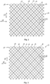
- the device comprises an expandable mesh 10 having a plurality of interwoven wires 11, 12.
- the wires 11, 12 cross each other and form intersection points. Furthermore, the wires 11, 12 and the intersection points delimit meshes 16 of the mesh 10.
- the mesh 10 is arranged in a wall plane of the medical device that extends rotationally symmetrically around a longitudinal axis of the medical device.
- the wall plane in which the mesh 10 is arranged can be shaped like a circular cylinder.
- the wires 11, 12 run helically around the longitudinal axis of the mesh 10 within the mesh 10.
- the wires 11, 12 can run helically around the longitudinal axis in opposite directions, at least in sections, so that the wires 11, 12 regularly cross each other.
- the wires 11, 12 form loops.
- the wires 11, 12 are thus deflected at the longitudinal end 15 of the mesh 10 and guided back into the mesh 10, forming closed loops 13, 14.
- the loops 13, 14 are each formed by a wire 11, 12 that is formed in one piece.
- the reinforcing loops 13 are arranged in a patterned manner over the longitudinal end 15.
- 50% of the loops 13, 14 of the longitudinal end 15 of the mesh 10 are designed as reinforcement loops 13.
- every second loop 13, 14 is designed as a reinforcement loop 13.
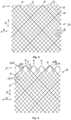
- every third loop 13, 14 is designed as a reinforcement loop 13. This corresponds to a percentage of approximately 33% of the loops 13, 14 of a longitudinal end 15.
- Fig. 3 shows an embodiment of the medical device according to the invention, wherein at the longitudinal end 15 of the mesh 10 approximately 17% of the loops 13, 14 are designed as reinforcement loops 13.
- every sixth loop is designed as a reinforcement loop.
- the mesh 10 has simple loops 13, 14 at each longitudinal end 15.
- the loops 13, 14 are arranged adjacent to or next to each other in the circumferential direction of the mesh 10.
- circumferential direction in the attached figures is oriented horizontally in the drawing plane and is indicated by a double arrow labeled UR.
- the longitudinal direction of the mesh 10 runs vertically in the drawing plane in the attached drawings and is indicated by a double arrow labeled LR.
- the mesh 10 can also have multiple loops 20 at a longitudinal end 15, as for example in Fig. 4
- the multiple loops 20 are formed by at least two loops 13, 14, which are arranged one behind the other in the longitudinal direction of the mesh 10.
- the longitudinal end 15 has several multiple loops 20, each formed by two individual loops 13, 14.
- Fig. 4 shows an expanded state of the mesh 10, in which the loops 13, 14 overlap congruently, at least in sections.
- an overlapping region 22 is provided in which a section of an outer loop 21a overlaps a section of an inner loop 21b. The radial force caused by the loops 13, 14 lying on top of one another in the radial direction relative to the longitudinal axis of the mesh 10 is summed in the overlapping region 22.
- the loops 13, 14 or the multiple loops 20 are arranged along a common circumferential line of the mesh 10, so that a straight-line longitudinal end 15 is formed.
- individual loops 13, 14 protrude beyond the longitudinal end 15 or beyond the other loops 13, 14.
- Fig. 5 an embodiment is shown, wherein reinforcement loops are provided which protrude beyond the other loops 14 of the longitudinal end 15.
- the reinforcement loops 13 are each assigned to a multiple loop 20 or form a multiple loop 20 with further loops 14.
- the multiple loop 20 has an outer loop 21a and two inner loops 21b, wherein the outer loop 21a is designed as a reinforcement loop 13. A different number of inner loops 21b is possible.
- the multiple loop 20 can comprise a plurality of individual loops 13, 14, wherein one or more individual loops 13, 14 are designed as reinforcement loops 13.
- all individual loops 13, 14 of a multiple loop 20 can also be designed as reinforcement loops.
- every fourth loop is designed as a multiple loop 20 or reinforcement loop 13. Other patterns are possible.
- every fifth loop 13, 14 of the longitudinal end 15 of the mesh 10 is designed as a multiple loop 20 or as a reinforcement loop 13.
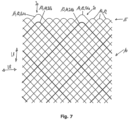
- the multiple loops 20 of the mesh 10 according to Fig. 6 each have an outer loop 21a and an inner loop 21b, wherein the outer loop 21a is designed as a reinforcement loop 13.
- the reinforcement loop 13 protrudes beyond the other loops 14, which are designed as individual loops.
- the embodiment according to Fig. 7 essentially corresponds to the embodiment according to Fig. 6 , with the difference that the inner loop 21b of the multiple loop 20 is designed as a reinforcement loop 13.
- the reinforcement loop 13 is set back from the other loops 14, which are designed as single loops.
- the mesh 10 comprises twelve double loops at one longitudinal end 15, i.e., multiple loops 20 formed from two loops 13, 14. Two of the twelve double loops each have a reinforcement loop 13. The remaining ten double loops, however, are formed from other loops 14, whose wires 12 each have the same cross-sectional diameter.
- the outer loop is preferably designed as a reinforcement loop 13.
- the wire 11 forming the reinforcement loop 13 preferably has a cross-sectional diameter of 85 ⁇ m.
- the wires 12 of the other loops 14 preferably have a cross-sectional diameter of 35 ⁇ m.
- the longitudinal end 15 of the mesh 10 preferably has 12 double loops, each having an inner loop 21b, the wire 12 of which has a cross-sectional diameter of 35 ⁇ m.
- Two of the 12 double loops each have an outer loop 21a whose wire has a cross-sectional diameter of 85 ⁇ m.
- the wire of the outer loop 21a of the remaining ten double loops has the same cross-sectional diameter as the wire of the inner loops 21b, i.e., 35 ⁇ m.
- the longitudinal end 15 has 24 individual loops 13, 14, two of the individual loops 13, 14 being designed as reinforcement loops 13.
- the multiple loops 20 may have more than one reinforcing loop 13.
- the mesh 10 has, in particular, six, in particular, at most four, in particular, at most three, in particular, at most two, multiple loops 20, each of which has at least one reinforcing loop 13, in particular, exclusively a single reinforcing loop 13.
- the ratio of the number of reinforcement loops 13 to the total number of loops is at most 34%, in particular at most 1:4, in particular at most 1:6, in particular at most 1:8, in particular at most 1:10, in particular at most 1:12, in particular at most 1:16, in particular at most 1:18, in particular at most 1:24.
- only double loops can be provided at the longitudinal end 15 of the mesh 10, each comprising a single reinforcement loop 13, in order to set a ratio between the number of reinforcement loops 13 and the total number of loops of 1:2.
- the reinforcement loops 13 each form the outer loops 21a of a multiple loop 20.
Landscapes
- Health & Medical Sciences (AREA)
- Engineering & Computer Science (AREA)
- Biomedical Technology (AREA)
- Cardiology (AREA)
- Oral & Maxillofacial Surgery (AREA)
- Transplantation (AREA)
- Heart & Thoracic Surgery (AREA)
- Vascular Medicine (AREA)
- Life Sciences & Earth Sciences (AREA)
- Animal Behavior & Ethology (AREA)
- General Health & Medical Sciences (AREA)
- Public Health (AREA)
- Veterinary Medicine (AREA)
- Prostheses (AREA)
Claims (7)
- Dispositif médical avec un treillis expansible (10) constitué de fils (11, 12) entrecroisés qui forment des boucles (13, 14) à au moins une extrémité longitudinale (15) du treillis (10), dans lequel au moins une boucle (13, 14) est réalisée en tant que boucle de renforcement (13) qui est formée par un fil (11) présentant, dans la zone de la boucle de renforcement (13), un diamètre transversal supérieur à celui des fils (12) qui forment les autres boucles (14),dans lequel on prévoit plusieurs boucles de renforcement (13),caractérisé en ce que les boucles de renforcement (13) sont disposées de façon répartie à la manière d'un motif sur l'extrémité longitudinale (15), dans lequel un maximum de 34 % des boucles (13, 14) sont réalisées en tant que boucles de renforcement (13).
- Dispositif médical selon la revendication 1,
caractérisé en ce
qu'un maximum de 17 % des boucles (13, 14) sont réalisées en tant que boucles de renforcement (13). - Dispositif médical selon la revendication 1 ou 2,
caractérisé en ce que
la boucle de renforcement (13) est en saillie en direction longitudinale du treillis (10) par rapport aux autres boucles (14) ou est en retrait compte tenu des autres boucles (14). - Dispositif médical selon l'une des revendications 1 à 3,
caractérisé en ce que
la boucle de renforcement (13) et au moins une autre boucle (14) sont disposées l'une derrière l'autre en direction longitudinale du treillis (10) et forment une boucle multiple (20). - Dispositif médical selon la revendication 4,
caractérisé en ce que
la boucle de renforcement (13) forme une boucle extérieure (21a) ou une boucle intérieure (21b) de la boucle multiple (20). - Dispositif médical selon la revendication 4 ou 5,
caractérisé en ce que,
dans un état d'expansion du treillis (10), la boucle de renforcement (13) et l'autre boucle (14) de la boucle multiple (20) sont disposées au moins partiellement l'une au-dessus de l'autre de façon coïncidente, et sont disposées à distance l'une de l'autre dans un état comprimé du treillis (10). - Dispositif médical selon l'une des revendications 4 à 6,
caractérisé en ce que
le rapport entre les boucles multiples avec au moins une boucle de renforcement (13) et le nombre total des boucles multiples est d'un maximum de 1/2, en particulier d'un maximum de 1/3, en particulier d'un maximum de 1/4, en particulier d'un maximum de 1/6, en particulier d'un maximum de 1/12.
Applications Claiming Priority (2)
| Application Number | Priority Date | Filing Date | Title |
|---|---|---|---|
| DE102011011180.8A DE102011011180B4 (de) | 2011-02-14 | 2011-02-14 | Medizinische Vorrichtung mit einem expandierbaren Gittergeflecht |
| PCT/EP2012/052287 WO2012110414A1 (fr) | 2011-02-14 | 2012-02-10 | Dispositif médical comprenant un treillis métallique expansible |
Publications (3)
| Publication Number | Publication Date |
|---|---|
| EP2675403A1 EP2675403A1 (fr) | 2013-12-25 |
| EP2675403B1 EP2675403B1 (fr) | 2016-12-07 |
| EP2675403B2 true EP2675403B2 (fr) | 2025-03-12 |
Family
ID=45592384
Family Applications (1)
| Application Number | Title | Priority Date | Filing Date |
|---|---|---|---|
| EP12703793.5A Active EP2675403B2 (fr) | 2011-02-14 | 2012-02-10 | Dispositif médical comprenant un treillis métallique expansible |
Country Status (3)
| Country | Link |
|---|---|
| EP (1) | EP2675403B2 (fr) |
| DE (1) | DE102011011180B4 (fr) |
| WO (1) | WO2012110414A1 (fr) |
Families Citing this family (5)
| Publication number | Priority date | Publication date | Assignee | Title |
|---|---|---|---|---|
| DE102011102935A1 (de) * | 2011-05-31 | 2012-12-06 | Acandis Gmbh & Co. Kg | Medizinische Vorrichtung zur Einfuhr in ein Körperhohlorgan |
| KR101922321B1 (ko) * | 2014-04-08 | 2018-11-26 | 보스톤 싸이엔티픽 싸이메드 인코포레이티드 | 의학 장치 및 이의 관련 사용 방법 |
| ES2922310T3 (es) * | 2017-11-06 | 2022-09-13 | Ea Pharma Co Ltd | Endoprótesis y dispositivo médico que comprende la misma |
| DE102018107594B4 (de) * | 2018-03-29 | 2022-09-15 | Acandis Gmbh | Medizinische Vorrichtung zur intravaskulären Behandlung und Herstellungsverfahren |
| CN115624423A (zh) * | 2021-07-14 | 2023-01-20 | 神途医疗科技(上海)有限公司 | 医疗支架 |
Citations (18)
| Publication number | Priority date | Publication date | Assignee | Title |
|---|---|---|---|---|
| EP0923912A2 (fr) † | 1997-12-18 | 1999-06-23 | Schneider (Usa) Inc. | Implant endoluminal avec support structurel biodégradable |
| DE19750971A1 (de) † | 1997-11-18 | 1999-07-08 | Schneider Europ Gmbh | Stent zur Implantation im menschlichen Körper, insbesondere in Blutgefäße |
| WO2001035864A1 (fr) † | 1999-11-16 | 2001-05-25 | Boston Scientific Limited | Stent endoluminal filamentaire multi-section |
| WO2001054621A1 (fr) † | 2000-01-31 | 2001-08-02 | Boston Scientific Limited | Endoprothese vasculaire ramifiee tressee, procede permettant de traiter une lumiere avec ladite endoprothese, et son procede de realisation |
| DE10127602A1 (de) † | 2001-05-31 | 2002-12-05 | Impag Gmbh Medizintechnik | Stent zur Implantation im menschlichen Körper |
| US20020179166A1 (en) † | 2001-06-05 | 2002-12-05 | Houston John Graeme | Flow means |
| US20040153117A1 (en) † | 2003-01-30 | 2004-08-05 | Clubb Thomas L. | Embolic filters with controlled pore size |
| WO2004105647A1 (fr) † | 2003-05-23 | 2004-12-09 | Scimed Life Systems, Inc. | Stents a extremites en boucle attachees |
| JP2006296559A (ja) † | 2005-04-18 | 2006-11-02 | Univ Kansai Medical | 金属および生体吸収性材料の複合材料による医療用ステント、その製法及びこれに用いる編機 |
| US20070208373A1 (en) † | 2006-02-22 | 2007-09-06 | Zaver Steven G | Embolic protection systems having radiopaque filter mesh |
| WO2008130530A1 (fr) † | 2007-04-16 | 2008-10-30 | Boston Scientific Scimed, Inc. | Compositions, endoprothèses vasculaires radio-opaques, et procédés de préparation |
| US20080275540A1 (en) † | 2005-11-09 | 2008-11-06 | Ning Wen | Artificial Heart Valve Stent and Weaving Method Thereof |
| DE202008014828U1 (de) † | 2007-11-07 | 2009-02-12 | Acandis Gmbh & Co. Kg | Medizinisches Implantat und Vorrichtung zur Herstellung eines derartigen Implantats |
| US20090082840A1 (en) † | 2007-09-24 | 2009-03-26 | Boston Scientific Scimed, Inc. | Method for loading a stent into a delivery system |
| WO2010034453A1 (fr) † | 2008-09-23 | 2010-04-01 | Acandis Gmbh & Co. Kg | Dispositif médical |
| DE102009006180A1 (de) † | 2008-10-29 | 2010-05-06 | Acandis Gmbh & Co. Kg | Medizinisches Implantat und Verfahren zum Herstellen eines Implantats |
| GB2470484A (en) † | 2009-05-20 | 2010-11-24 | Arsenal Medical Inc | Implantable medical device comprising self-expanding tubular structure |
| WO2012082440A1 (fr) † | 2010-12-13 | 2012-06-21 | Microvention, Inc. | Endoprothèse |
Family Cites Families (5)
| Publication number | Priority date | Publication date | Assignee | Title |
|---|---|---|---|---|
| US7018401B1 (en) * | 1999-02-01 | 2006-03-28 | Board Of Regents, The University Of Texas System | Woven intravascular devices and methods for making the same and apparatus for delivery of the same |
| FR2858208B1 (fr) * | 2003-07-28 | 2006-04-14 | Perouse Laboratoires | Endoprothese comprenant un treillis tubulaire. |
| US9526609B2 (en) * | 2003-12-23 | 2016-12-27 | Boston Scientific Scimed, Inc. | Methods and apparatus for endovascularly replacing a patient's heart valve |
| WO2006053270A2 (fr) * | 2004-11-10 | 2006-05-18 | Boston Scientific Limited | Endoprothese vasculaire atraumatique a force de deploiement reduite, procede de fabrication de cette derniere et procede et appareil de deploiement et de positionnement de l'endoprothese vasculaire |
| US8652201B2 (en) * | 2006-04-26 | 2014-02-18 | The Cleveland Clinic Foundation | Apparatus and method for treating cardiovascular diseases |
-
2011
- 2011-02-14 DE DE102011011180.8A patent/DE102011011180B4/de active Active
-
2012
- 2012-02-10 EP EP12703793.5A patent/EP2675403B2/fr active Active
- 2012-02-10 WO PCT/EP2012/052287 patent/WO2012110414A1/fr not_active Ceased
Patent Citations (18)
| Publication number | Priority date | Publication date | Assignee | Title |
|---|---|---|---|---|
| DE19750971A1 (de) † | 1997-11-18 | 1999-07-08 | Schneider Europ Gmbh | Stent zur Implantation im menschlichen Körper, insbesondere in Blutgefäße |
| EP0923912A2 (fr) † | 1997-12-18 | 1999-06-23 | Schneider (Usa) Inc. | Implant endoluminal avec support structurel biodégradable |
| WO2001035864A1 (fr) † | 1999-11-16 | 2001-05-25 | Boston Scientific Limited | Stent endoluminal filamentaire multi-section |
| WO2001054621A1 (fr) † | 2000-01-31 | 2001-08-02 | Boston Scientific Limited | Endoprothese vasculaire ramifiee tressee, procede permettant de traiter une lumiere avec ladite endoprothese, et son procede de realisation |
| DE10127602A1 (de) † | 2001-05-31 | 2002-12-05 | Impag Gmbh Medizintechnik | Stent zur Implantation im menschlichen Körper |
| US20020179166A1 (en) † | 2001-06-05 | 2002-12-05 | Houston John Graeme | Flow means |
| US20040153117A1 (en) † | 2003-01-30 | 2004-08-05 | Clubb Thomas L. | Embolic filters with controlled pore size |
| WO2004105647A1 (fr) † | 2003-05-23 | 2004-12-09 | Scimed Life Systems, Inc. | Stents a extremites en boucle attachees |
| JP2006296559A (ja) † | 2005-04-18 | 2006-11-02 | Univ Kansai Medical | 金属および生体吸収性材料の複合材料による医療用ステント、その製法及びこれに用いる編機 |
| US20080275540A1 (en) † | 2005-11-09 | 2008-11-06 | Ning Wen | Artificial Heart Valve Stent and Weaving Method Thereof |
| US20070208373A1 (en) † | 2006-02-22 | 2007-09-06 | Zaver Steven G | Embolic protection systems having radiopaque filter mesh |
| WO2008130530A1 (fr) † | 2007-04-16 | 2008-10-30 | Boston Scientific Scimed, Inc. | Compositions, endoprothèses vasculaires radio-opaques, et procédés de préparation |
| US20090082840A1 (en) † | 2007-09-24 | 2009-03-26 | Boston Scientific Scimed, Inc. | Method for loading a stent into a delivery system |
| DE202008014828U1 (de) † | 2007-11-07 | 2009-02-12 | Acandis Gmbh & Co. Kg | Medizinisches Implantat und Vorrichtung zur Herstellung eines derartigen Implantats |
| WO2010034453A1 (fr) † | 2008-09-23 | 2010-04-01 | Acandis Gmbh & Co. Kg | Dispositif médical |
| DE102009006180A1 (de) † | 2008-10-29 | 2010-05-06 | Acandis Gmbh & Co. Kg | Medizinisches Implantat und Verfahren zum Herstellen eines Implantats |
| GB2470484A (en) † | 2009-05-20 | 2010-11-24 | Arsenal Medical Inc | Implantable medical device comprising self-expanding tubular structure |
| WO2012082440A1 (fr) † | 2010-12-13 | 2012-06-21 | Microvention, Inc. | Endoprothèse |
Also Published As
| Publication number | Publication date |
|---|---|
| DE102011011180A1 (de) | 2012-08-16 |
| EP2675403A1 (fr) | 2013-12-25 |
| EP2675403B1 (fr) | 2016-12-07 |
| DE102011011180B4 (de) | 2015-10-01 |
| WO2012110414A1 (fr) | 2012-08-23 |
Similar Documents
| Publication | Publication Date | Title |
|---|---|---|
| EP3415122B1 (fr) | Procédé de fabrication d'un stent | |
| EP2991593B1 (fr) | Dispositif médical destiné à être introduit dans un organe creux du corps | |
| DE102010008360A1 (de) | Medizinisches Implantat, in welchem beim Crimpen bzw. Falten Lücken verbleiben, Verfahren und Einrichtung zum Verbringen | |
| DE102010008362A1 (de) | Medizinisches Implantat, welches aus einem nicht expandierten Zustand expandierbar ist | |
| DE102009041025A1 (de) | Medizinisches Implantat | |
| DE102010035543A1 (de) | Medizinische Vorrichtung und System mit einer derartigen Vorrichtung | |
| EP2675403B2 (fr) | Dispositif médical comprenant un treillis métallique expansible | |
| DE102012107175B4 (de) | Medizinische Verschlussvorrichtung und System mit einer derartigen Verschlussvorrichtung | |
| DE102009042121B3 (de) | Medizinisches Gerät zum Einführen in ein Körperhohlorgan | |
| DE102012101294A1 (de) | Medizinsche Vorrichtung | |
| EP1555959B1 (fr) | Endoprothese a implanter dans ou autour d'un organe creux | |
| EP2667831B1 (fr) | Dispositif médical doté d'une structure en treillis et système de traitement doté d'un tel dispositif | |
| EP2823793B1 (fr) | Endoprothèse pour vaisseaux contournés | |
| DE102012112730B4 (de) | Medizinische Vorrichtung, insbesondere Stent, medizinisches System mit einer derartigen Vorrichtung und Herstellungsverfahren | |
| DE102010026830A1 (de) | Medizinische Vorrichtung und Verfahren zur Herstellung eines derartigen Vorrichtung | |
| EP2675404B1 (fr) | Dispositif médical doté d'une maille tressée extensible | |
| EP2895117B1 (fr) | Stent | |
| EP4417167A1 (fr) | Dispositif médical et système de traitement | |
| DE102007030753A1 (de) | Stent | |
| DE202020106807U1 (de) | Medizinisches Set zur Behandlung von Blutgefäßerkrankungen | |
| EP2572681A1 (fr) | Implant et son procédé de fabrication | |
| DE20114667U1 (de) | Aufweitbares Netz | |
| DE102013109456B4 (de) | Medizinische Vorrichtung mit einer gewölbten, insbesondere rohrförmigen, Gitterstruktur und Set mit einer derartigen medizinischen Vorrichtung | |
| DE102011102936B4 (de) | Medizinische Vorrichtung zur Einfuhr in ein Hohlorgan | |
| DE102009010825A1 (de) | Medizinisches Implantat mit einer Gitterstruktur, Verfahren zu dessen Herstellung sowie Verfahren zum Einbringen des medizinischen Implantats in ein Zufuhrsystem |
Legal Events
| Date | Code | Title | Description |
|---|---|---|---|
| PUAI | Public reference made under article 153(3) epc to a published international application that has entered the european phase |
Free format text: ORIGINAL CODE: 0009012 |
|
| 17P | Request for examination filed |
Effective date: 20130723 |
|
| AK | Designated contracting states |
Kind code of ref document: A1 Designated state(s): AL AT BE BG CH CY CZ DE DK EE ES FI FR GB GR HR HU IE IS IT LI LT LU LV MC MK MT NL NO PL PT RO RS SE SI SK SM TR |
|
| DAX | Request for extension of the european patent (deleted) | ||
| GRAP | Despatch of communication of intention to grant a patent |
Free format text: ORIGINAL CODE: EPIDOSNIGR1 |
|
| INTG | Intention to grant announced |
Effective date: 20160519 |
|
| GRAP | Despatch of communication of intention to grant a patent |
Free format text: ORIGINAL CODE: EPIDOSNIGR1 |
|
| INTG | Intention to grant announced |
Effective date: 20160701 |
|
| GRAS | Grant fee paid |
Free format text: ORIGINAL CODE: EPIDOSNIGR3 |
|
| STAA | Information on the status of an ep patent application or granted ep patent |
Free format text: STATUS: GRANT OF PATENT IS INTENDED |
|
| GRAA | (expected) grant |
Free format text: ORIGINAL CODE: 0009210 |
|
| STAA | Information on the status of an ep patent application or granted ep patent |
Free format text: STATUS: THE PATENT HAS BEEN GRANTED |
|
| AK | Designated contracting states |
Kind code of ref document: B1 Designated state(s): AL AT BE BG CH CY CZ DE DK EE ES FI FR GB GR HR HU IE IS IT LI LT LU LV MC MK MT NL NO PL PT RO RS SE SI SK SM TR |
|
| REG | Reference to a national code |
Ref country code: GB Ref legal event code: FG4D Free format text: NOT ENGLISH |
|
| REG | Reference to a national code |
Ref country code: CH Ref legal event code: EP Ref country code: AT Ref legal event code: REF Ref document number: 851074 Country of ref document: AT Kind code of ref document: T Effective date: 20161215 |
|
| REG | Reference to a national code |
Ref country code: IE Ref legal event code: FG4D Free format text: LANGUAGE OF EP DOCUMENT: GERMAN |
|
| REG | Reference to a national code |
Ref country code: DE Ref legal event code: R096 Ref document number: 502012008966 Country of ref document: DE |
|
| REG | Reference to a national code |
Ref country code: FR Ref legal event code: PLFP Year of fee payment: 6 |
|
| PG25 | Lapsed in a contracting state [announced via postgrant information from national office to epo] |
Ref country code: LV Free format text: LAPSE BECAUSE OF FAILURE TO SUBMIT A TRANSLATION OF THE DESCRIPTION OR TO PAY THE FEE WITHIN THE PRESCRIBED TIME-LIMIT Effective date: 20161207 |
|
| REG | Reference to a national code |
Ref country code: LT Ref legal event code: MG4D |
|
| REG | Reference to a national code |
Ref country code: NL Ref legal event code: MP Effective date: 20161207 |
|
| PG25 | Lapsed in a contracting state [announced via postgrant information from national office to epo] |
Ref country code: NO Free format text: LAPSE BECAUSE OF FAILURE TO SUBMIT A TRANSLATION OF THE DESCRIPTION OR TO PAY THE FEE WITHIN THE PRESCRIBED TIME-LIMIT Effective date: 20170307 Ref country code: LT Free format text: LAPSE BECAUSE OF FAILURE TO SUBMIT A TRANSLATION OF THE DESCRIPTION OR TO PAY THE FEE WITHIN THE PRESCRIBED TIME-LIMIT Effective date: 20161207 Ref country code: SE Free format text: LAPSE BECAUSE OF FAILURE TO SUBMIT A TRANSLATION OF THE DESCRIPTION OR TO PAY THE FEE WITHIN THE PRESCRIBED TIME-LIMIT Effective date: 20161207 Ref country code: GR Free format text: LAPSE BECAUSE OF FAILURE TO SUBMIT A TRANSLATION OF THE DESCRIPTION OR TO PAY THE FEE WITHIN THE PRESCRIBED TIME-LIMIT Effective date: 20170308 |
|
| PG25 | Lapsed in a contracting state [announced via postgrant information from national office to epo] |
Ref country code: HR Free format text: LAPSE BECAUSE OF FAILURE TO SUBMIT A TRANSLATION OF THE DESCRIPTION OR TO PAY THE FEE WITHIN THE PRESCRIBED TIME-LIMIT Effective date: 20161207 Ref country code: RS Free format text: LAPSE BECAUSE OF FAILURE TO SUBMIT A TRANSLATION OF THE DESCRIPTION OR TO PAY THE FEE WITHIN THE PRESCRIBED TIME-LIMIT Effective date: 20161207 Ref country code: BE Free format text: LAPSE BECAUSE OF NON-PAYMENT OF DUE FEES Effective date: 20170228 Ref country code: ES Free format text: LAPSE BECAUSE OF FAILURE TO SUBMIT A TRANSLATION OF THE DESCRIPTION OR TO PAY THE FEE WITHIN THE PRESCRIBED TIME-LIMIT Effective date: 20161207 Ref country code: FI Free format text: LAPSE BECAUSE OF FAILURE TO SUBMIT A TRANSLATION OF THE DESCRIPTION OR TO PAY THE FEE WITHIN THE PRESCRIBED TIME-LIMIT Effective date: 20161207 |
|
| PG25 | Lapsed in a contracting state [announced via postgrant information from national office to epo] |
Ref country code: NL Free format text: LAPSE BECAUSE OF FAILURE TO SUBMIT A TRANSLATION OF THE DESCRIPTION OR TO PAY THE FEE WITHIN THE PRESCRIBED TIME-LIMIT Effective date: 20161207 |
|
| PG25 | Lapsed in a contracting state [announced via postgrant information from national office to epo] |
Ref country code: EE Free format text: LAPSE BECAUSE OF FAILURE TO SUBMIT A TRANSLATION OF THE DESCRIPTION OR TO PAY THE FEE WITHIN THE PRESCRIBED TIME-LIMIT Effective date: 20161207 Ref country code: CZ Free format text: LAPSE BECAUSE OF FAILURE TO SUBMIT A TRANSLATION OF THE DESCRIPTION OR TO PAY THE FEE WITHIN THE PRESCRIBED TIME-LIMIT Effective date: 20161207 Ref country code: SK Free format text: LAPSE BECAUSE OF FAILURE TO SUBMIT A TRANSLATION OF THE DESCRIPTION OR TO PAY THE FEE WITHIN THE PRESCRIBED TIME-LIMIT Effective date: 20161207 Ref country code: RO Free format text: LAPSE BECAUSE OF FAILURE TO SUBMIT A TRANSLATION OF THE DESCRIPTION OR TO PAY THE FEE WITHIN THE PRESCRIBED TIME-LIMIT Effective date: 20161207 Ref country code: IS Free format text: LAPSE BECAUSE OF FAILURE TO SUBMIT A TRANSLATION OF THE DESCRIPTION OR TO PAY THE FEE WITHIN THE PRESCRIBED TIME-LIMIT Effective date: 20170407 |
|
| PG25 | Lapsed in a contracting state [announced via postgrant information from national office to epo] |
Ref country code: SM Free format text: LAPSE BECAUSE OF FAILURE TO SUBMIT A TRANSLATION OF THE DESCRIPTION OR TO PAY THE FEE WITHIN THE PRESCRIBED TIME-LIMIT Effective date: 20161207 Ref country code: PL Free format text: LAPSE BECAUSE OF FAILURE TO SUBMIT A TRANSLATION OF THE DESCRIPTION OR TO PAY THE FEE WITHIN THE PRESCRIBED TIME-LIMIT Effective date: 20161207 Ref country code: BG Free format text: LAPSE BECAUSE OF FAILURE TO SUBMIT A TRANSLATION OF THE DESCRIPTION OR TO PAY THE FEE WITHIN THE PRESCRIBED TIME-LIMIT Effective date: 20170307 Ref country code: IT Free format text: LAPSE BECAUSE OF FAILURE TO SUBMIT A TRANSLATION OF THE DESCRIPTION OR TO PAY THE FEE WITHIN THE PRESCRIBED TIME-LIMIT Effective date: 20161207 Ref country code: PT Free format text: LAPSE BECAUSE OF FAILURE TO SUBMIT A TRANSLATION OF THE DESCRIPTION OR TO PAY THE FEE WITHIN THE PRESCRIBED TIME-LIMIT Effective date: 20170407 |
|
| REG | Reference to a national code |
Ref country code: DE Ref legal event code: R026 Ref document number: 502012008966 Country of ref document: DE |
|
| PLBI | Opposition filed |
Free format text: ORIGINAL CODE: 0009260 |
|
| PG25 | Lapsed in a contracting state [announced via postgrant information from national office to epo] |
Ref country code: MC Free format text: LAPSE BECAUSE OF FAILURE TO SUBMIT A TRANSLATION OF THE DESCRIPTION OR TO PAY THE FEE WITHIN THE PRESCRIBED TIME-LIMIT Effective date: 20161207 |
|
| REG | Reference to a national code |
Ref country code: CH Ref legal event code: PL |
|
| PLAX | Notice of opposition and request to file observation + time limit sent |
Free format text: ORIGINAL CODE: EPIDOSNOBS2 |
|
| 26 | Opposition filed |
Opponent name: BOSTON SCIENTIFIC SCIMED, INC. Effective date: 20170907 |
|
| PG25 | Lapsed in a contracting state [announced via postgrant information from national office to epo] |
Ref country code: LI Free format text: LAPSE BECAUSE OF NON-PAYMENT OF DUE FEES Effective date: 20170228 Ref country code: CH Free format text: LAPSE BECAUSE OF NON-PAYMENT OF DUE FEES Effective date: 20170228 |
|
| REG | Reference to a national code |
Ref country code: IE Ref legal event code: MM4A |
|
| PG25 | Lapsed in a contracting state [announced via postgrant information from national office to epo] |
Ref country code: SI Free format text: LAPSE BECAUSE OF FAILURE TO SUBMIT A TRANSLATION OF THE DESCRIPTION OR TO PAY THE FEE WITHIN THE PRESCRIBED TIME-LIMIT Effective date: 20161207 Ref country code: DK Free format text: LAPSE BECAUSE OF FAILURE TO SUBMIT A TRANSLATION OF THE DESCRIPTION OR TO PAY THE FEE WITHIN THE PRESCRIBED TIME-LIMIT Effective date: 20161207 |
|
| PG25 | Lapsed in a contracting state [announced via postgrant information from national office to epo] |
Ref country code: LU Free format text: LAPSE BECAUSE OF NON-PAYMENT OF DUE FEES Effective date: 20170210 |
|
| REG | Reference to a national code |
Ref country code: BE Ref legal event code: MM Effective date: 20170228 |
|
| REG | Reference to a national code |
Ref country code: FR Ref legal event code: PLFP Year of fee payment: 7 |
|
| PLBB | Reply of patent proprietor to notice(s) of opposition received |
Free format text: ORIGINAL CODE: EPIDOSNOBS3 |
|
| PG25 | Lapsed in a contracting state [announced via postgrant information from national office to epo] |
Ref country code: IE Free format text: LAPSE BECAUSE OF NON-PAYMENT OF DUE FEES Effective date: 20170210 |
|
| REG | Reference to a national code |
Ref country code: AT Ref legal event code: MM01 Ref document number: 851074 Country of ref document: AT Kind code of ref document: T Effective date: 20170210 |
|
| PG25 | Lapsed in a contracting state [announced via postgrant information from national office to epo] |
Ref country code: AT Free format text: LAPSE BECAUSE OF NON-PAYMENT OF DUE FEES Effective date: 20170210 |
|
| REG | Reference to a national code |
Ref country code: DE Ref legal event code: R082 Ref document number: 502012008966 Country of ref document: DE Representative=s name: MEISSNER BOLTE PATENTANWAELTE RECHTSANWAELTE P, DE Ref country code: DE Ref legal event code: R081 Ref document number: 502012008966 Country of ref document: DE Owner name: ACANDIS GMBH, DE Free format text: FORMER OWNER: ACANDIS GMBH & CO. KG, 76327 PFINZTAL, DE |
|
| PG25 | Lapsed in a contracting state [announced via postgrant information from national office to epo] |
Ref country code: MT Free format text: LAPSE BECAUSE OF FAILURE TO SUBMIT A TRANSLATION OF THE DESCRIPTION OR TO PAY THE FEE WITHIN THE PRESCRIBED TIME-LIMIT Effective date: 20161207 |
|
| APBM | Appeal reference recorded |
Free format text: ORIGINAL CODE: EPIDOSNREFNO |
|
| APBP | Date of receipt of notice of appeal recorded |
Free format text: ORIGINAL CODE: EPIDOSNNOA2O |
|
| APAH | Appeal reference modified |
Free format text: ORIGINAL CODE: EPIDOSCREFNO |
|
| PG25 | Lapsed in a contracting state [announced via postgrant information from national office to epo] |
Ref country code: HU Free format text: LAPSE BECAUSE OF FAILURE TO SUBMIT A TRANSLATION OF THE DESCRIPTION OR TO PAY THE FEE WITHIN THE PRESCRIBED TIME-LIMIT; INVALID AB INITIO Effective date: 20120210 |
|
| APBQ | Date of receipt of statement of grounds of appeal recorded |
Free format text: ORIGINAL CODE: EPIDOSNNOA3O |
|
| PG25 | Lapsed in a contracting state [announced via postgrant information from national office to epo] |
Ref country code: CY Free format text: LAPSE BECAUSE OF NON-PAYMENT OF DUE FEES Effective date: 20161207 |
|
| PG25 | Lapsed in a contracting state [announced via postgrant information from national office to epo] |
Ref country code: MK Free format text: LAPSE BECAUSE OF FAILURE TO SUBMIT A TRANSLATION OF THE DESCRIPTION OR TO PAY THE FEE WITHIN THE PRESCRIBED TIME-LIMIT Effective date: 20161207 |
|
| PG25 | Lapsed in a contracting state [announced via postgrant information from national office to epo] |
Ref country code: TR Free format text: LAPSE BECAUSE OF FAILURE TO SUBMIT A TRANSLATION OF THE DESCRIPTION OR TO PAY THE FEE WITHIN THE PRESCRIBED TIME-LIMIT Effective date: 20161207 |
|
| PGFP | Annual fee paid to national office [announced via postgrant information from national office to epo] |
Ref country code: GB Payment date: 20200226 Year of fee payment: 9 |
|
| PGFP | Annual fee paid to national office [announced via postgrant information from national office to epo] |
Ref country code: FR Payment date: 20200225 Year of fee payment: 9 |
|
| PG25 | Lapsed in a contracting state [announced via postgrant information from national office to epo] |
Ref country code: AL Free format text: LAPSE BECAUSE OF FAILURE TO SUBMIT A TRANSLATION OF THE DESCRIPTION OR TO PAY THE FEE WITHIN THE PRESCRIBED TIME-LIMIT Effective date: 20161207 |
|
| GBPC | Gb: european patent ceased through non-payment of renewal fee |
Effective date: 20210210 |
|
| PG25 | Lapsed in a contracting state [announced via postgrant information from national office to epo] |
Ref country code: FR Free format text: LAPSE BECAUSE OF NON-PAYMENT OF DUE FEES Effective date: 20210228 Ref country code: GB Free format text: LAPSE BECAUSE OF NON-PAYMENT OF DUE FEES Effective date: 20210210 |
|
| APBU | Appeal procedure closed |
Free format text: ORIGINAL CODE: EPIDOSNNOA9O |
|
| PLAY | Examination report in opposition despatched + time limit |
Free format text: ORIGINAL CODE: EPIDOSNORE2 |
|
| PLBC | Reply to examination report in opposition received |
Free format text: ORIGINAL CODE: EPIDOSNORE3 |
|
| P01 | Opt-out of the competence of the unified patent court (upc) registered |
Effective date: 20230603 |
|
| PLAY | Examination report in opposition despatched + time limit |
Free format text: ORIGINAL CODE: EPIDOSNORE2 |
|
| PUAH | Patent maintained in amended form |
Free format text: ORIGINAL CODE: 0009272 |
|
| STAA | Information on the status of an ep patent application or granted ep patent |
Free format text: STATUS: PATENT MAINTAINED AS AMENDED |
|
| 27A | Patent maintained in amended form |
Effective date: 20250312 |
|
| AK | Designated contracting states |
Kind code of ref document: B2 Designated state(s): AL AT BE BG CH CY CZ DE DK EE ES FI FR GB GR HR HU IE IS IT LI LT LU LV MC MK MT NL NO PL PT RO RS SE SI SK SM TR |
|
| REG | Reference to a national code |
Ref country code: DE Ref legal event code: R102 Ref document number: 502012008966 Country of ref document: DE |
|
| PGFP | Annual fee paid to national office [announced via postgrant information from national office to epo] |
Ref country code: DE Payment date: 20260227 Year of fee payment: 15 |