EP2675603B1 - Système d'outil de moulage comprenant un ensemble canal de coulée configuré pour offrir un portail d'accès afin de permettre un accès à un ensemble - Google Patents
Système d'outil de moulage comprenant un ensemble canal de coulée configuré pour offrir un portail d'accès afin de permettre un accès à un ensemble Download PDFInfo
- Publication number
- EP2675603B1 EP2675603B1 EP12747505.1A EP12747505A EP2675603B1 EP 2675603 B1 EP2675603 B1 EP 2675603B1 EP 12747505 A EP12747505 A EP 12747505A EP 2675603 B1 EP2675603 B1 EP 2675603B1
- Authority
- EP
- European Patent Office
- Prior art keywords
- assembly
- stem
- mold
- runner
- adjustment
- Prior art date
- Legal status (The legal status is an assumption and is not a legal conclusion. Google has not performed a legal analysis and makes no representation as to the accuracy of the status listed.)
- Not-in-force
Links
Images






Classifications
-
- B—PERFORMING OPERATIONS; TRANSPORTING
- B29—WORKING OF PLASTICS; WORKING OF SUBSTANCES IN A PLASTIC STATE IN GENERAL
- B29C—SHAPING OR JOINING OF PLASTICS; SHAPING OF MATERIAL IN A PLASTIC STATE, NOT OTHERWISE PROVIDED FOR; AFTER-TREATMENT OF THE SHAPED PRODUCTS, e.g. REPAIRING
- B29C33/00—Moulds or cores; Details thereof or accessories therefor
- B29C33/30—Mounting, exchanging or centering
- B29C33/308—Adjustable moulds
-
- B—PERFORMING OPERATIONS; TRANSPORTING
- B29—WORKING OF PLASTICS; WORKING OF SUBSTANCES IN A PLASTIC STATE IN GENERAL
- B29C—SHAPING OR JOINING OF PLASTICS; SHAPING OF MATERIAL IN A PLASTIC STATE, NOT OTHERWISE PROVIDED FOR; AFTER-TREATMENT OF THE SHAPED PRODUCTS, e.g. REPAIRING
- B29C45/00—Injection moulding, i.e. forcing the required volume of moulding material through a nozzle into a closed mould; Apparatus therefor
- B29C45/17—Component parts, details or accessories; Auxiliary operations
- B29C45/26—Moulds
- B29C45/27—Sprue channels ; Runner channels or runner nozzles
- B29C45/28—Closure devices therefor
- B29C45/2806—Closure devices therefor consisting of needle valve systems
- B29C45/281—Drive means therefor
-
- B—PERFORMING OPERATIONS; TRANSPORTING
- B29—WORKING OF PLASTICS; WORKING OF SUBSTANCES IN A PLASTIC STATE IN GENERAL
- B29C—SHAPING OR JOINING OF PLASTICS; SHAPING OF MATERIAL IN A PLASTIC STATE, NOT OTHERWISE PROVIDED FOR; AFTER-TREATMENT OF THE SHAPED PRODUCTS, e.g. REPAIRING
- B29C45/00—Injection moulding, i.e. forcing the required volume of moulding material through a nozzle into a closed mould; Apparatus therefor
- B29C45/17—Component parts, details or accessories; Auxiliary operations
- B29C45/26—Moulds
- B29C45/27—Sprue channels ; Runner channels or runner nozzles
- B29C45/28—Closure devices therefor
- B29C45/2806—Closure devices therefor consisting of needle valve systems
- B29C45/281—Drive means therefor
- B29C2045/2813—Common drive means for several needle valves
-
- B—PERFORMING OPERATIONS; TRANSPORTING
- B29—WORKING OF PLASTICS; WORKING OF SUBSTANCES IN A PLASTIC STATE IN GENERAL
- B29C—SHAPING OR JOINING OF PLASTICS; SHAPING OF MATERIAL IN A PLASTIC STATE, NOT OTHERWISE PROVIDED FOR; AFTER-TREATMENT OF THE SHAPED PRODUCTS, e.g. REPAIRING
- B29C45/00—Injection moulding, i.e. forcing the required volume of moulding material through a nozzle into a closed mould; Apparatus therefor
- B29C45/17—Component parts, details or accessories; Auxiliary operations
- B29C45/26—Moulds
- B29C45/27—Sprue channels ; Runner channels or runner nozzles
- B29C45/28—Closure devices therefor
- B29C45/2806—Closure devices therefor consisting of needle valve systems
- B29C2045/2848—Closure devices therefor consisting of needle valve systems having an adjustable stroke length
Definitions
- An aspect relates to a mold-tool system.
- United States Patent Application No. 2010/0092588 to Tabassi published on April 15, 2010 , discloses an injection molding apparatus having magnetic valve pin coupling and related method.
- An actuated part such as a valve pin plate or actuator piston, is movable in forward and rearward directions.
- a coupling part is located rearward of the actuated part and held in position by magnetic attraction between the coupling part and the actuated part.
- a valve pin is coupled to the coupling part.
- the valve pin extends in the forward direction for opening and closing a mold gate.
- United States Patent Application No. 2010/0207289 to Feick et al. published on August 19, 2010 , discloses an injection molding apparatus having magnetic valve pin coupling.
- the magnetic coupling for an injection molding apparatus such as a hot half or hot runner, includes a first magnetic part for connection to an actuator, a valve pin plate, or the like and a movable second magnetic part for connection to a valve pin.
- the first magnetic part and the second magnetic part are coupled by a magnetic force.
- the first magnetic part can be part of the actuator.
- the second magnetic part can be part of the valve pin.
- a valve pin plate can be provided for a plurality of valve pins.
- An example of a fine tuning of an assembly of the runner assembly may be (and is not limited to): an assembly configured to adjust valve stem protrusion during mold qualification. Processing temperature may not be always known ahead of time and this may have an impact regarding the amount of stem protrusion that may be required.
- Known actuated stem plates may use a stop-pad assembly that may be configured to provide an amount of protrusion of a valve stem into a mold assembly. Several thicknesses of the stop pad assembly may be used, in small increments.
- the height of the stop-pad assembly may be chosen or selected so as to achieve a predetermined nominal protrusion of the valve stem (that is, protrusion of the valve stem into a mold assembly while the valve stem may be placed in a closed position or no flow position). Also, the correct stop-pad assembly selection may compensate for manufacturing stack up deviation.
- Known runner assemblies may require a few adjustments using the stop- pad assembly, then the stop-pad assembly may be locked in position for production (that is, to permit molding of articles by the molding system). The known approach may be time consuming due to disassembly of the runner assembly, usually on a bench (that is, the runner assembly may be disconnected from the molding system) in order to swap out the stop-pad assembly.
- FIGS. 1 , 2A, 2B depict the schematic representations of the molding system ( 500 ).
- FIGS. 3 , 4A , 4B , 5A , 5B , 6 , 7 , 8 , 9 , 10 , 11 , 12 , 13 , 14 depict the schematic representations of the mold-tool system ( 100 ) usable with the molding system ( 500 ) of FIGS. 1 , 2A, 2B .
- the molding system ( 500 ) and the mold-tool system ( 100 ), for example, may include components that are known to persons skilled in the art, and these known components will not be described here; these known components are described, at least in part, in the following reference books (for example): (i) " Injection Molding Handbook” authored by OSSWALD/TURNG/GRAMANN (ISBN: 3-446-21669-2 ), (ii) " Injection Molding Handbook” authored by ROSATO AND ROSATO (ISBN: 0-412-99381-3 ), (iii) " Injection Molding Systems” 3rd Edition authored by JOHANNABER (ISBN 3-446-17733-7 ) and/or (iv) " Runner and Gating Design Handbook” authored by BEAUMONT (ISBN 1-446-22672-9 ).
- the phrase “includes (but is not limited to)” is equivalent to the word “comprising”.
- the word “comprising” is a transitional phrase or word that links the preamble of a patent claim to the specific elements set forth in the claim, which define what the invention itself actually is.
- the transitional phrase acts as a limitation on the claim, indicating whether a similar device, method, or composition infringes the patent if the accused device (etc) contains more or fewer elements than the claim in the patent.
- the word “comprising” is to be treated as an open transition, which is the broadest form of transition, as it does not limit the preamble to whatever elements are identified in the claim.
- the definition of the mold-tool system ( 100 ) is as follows: a system that may be positioned and/or may be used in a molding envelope ( 533 ) defined by a stationary platen ( 504 ) and a movable platen ( 506 ) of the molding system ( 500 ), such as an injection-molding system for example.
- the mold-tool system ( 100 ) may be used with a mold assembly ( 700 ) and/or a runner assembly ( 600 ), and/or any sub-assembly or part thereof.
- FIG. 1 depicts a schematic representation of the molding system ( 500 ).
- the molding system ( 500 ) may include (and is not limited to) a melt preparation assembly ( 514 ) configured to prepare, in use, a melt, also called a flowable molding material.
- a runner assembly ( 600 ) is configured to receive the melt form the melt preparation assembly ( 514 ).
- the runner assembly ( 600 ) is configured to convey the melt from the melt preparation assembly ( 514 ) to the mold assembly ( 700 ).
- the runner assembly ( 600 ) may abut the mold assembly ( 700 ).
- the molding system ( 500 ), the runner assembly ( 600 ) and the mold assembly ( 700 ) may be provided by a single vendor or may be provided by different vendors.
- a clamping assembly ( 502 ) includes a stationary platen ( 504 ) and a movable platen ( 506 ).
- the movable platen ( 506 ) that is configured to be movable relative to the stationary platen ( 504 ).
- the mold assembly ( 700 ) may include a first mold portion ( 702 ) that may interface with the runner assembly ( 600 ).
- the mold assembly ( 700 ) may also include a second mold portion ( 704 ) that may interface (or be supported by) with the movable platen ( 506 ).
- the runner assembly ( 600 ) may be configured to be connected to or to be supported by the stationary platen ( 504 ).
- the mold assembly ( 700 ) may be configured to be connected to or to be supported by the movable platen ( 506 ).
- Rods ( 508 ) extend between stationary platen ( 504 ) and the movable platen ( 506 ).
- the movable platen ( 506 ) may be movable along the rods ( 508 ).
- Lock assembly ( 510 ) is supported at ends of the rods ( 508 ), and the lock assembly ( 510 ) is configured to lock and unlock the movable platen ( 506 ) relative to the stationary platen ( 504 ).
- Clamp units ( 512 ) are attached to other ends of the rods ( 508 ).
- FIGS. 2 A, 2 B depict schematic representation of the molding system ( 500 ) in a manufacturing mode of operation.
- FIG. 2 A depicts the case where in operation, the movable platen ( 506 ) may be moved toward stationary platen ( 504 ) so as to close the mold assembly ( 700 ).
- the clamp units ( 512 ) are configured to apply a clamping force to the stationary platen ( 504 ) and to the rods ( 508 ), which in turn is transferred to the lock assembly ( 510 ) and then to the movable platen ( 506 ).
- FIG. 2 B depicts the case where once the melt is solidified in the mold assembly ( 700 ), the movable platen ( 506 ) may be moved away from the stationary platen ( 504 ), so that the mold assembly ( 700 ) may be separated and thus allowing a molded article ( 800 ) to be removed from the mold assembly ( 700 ).
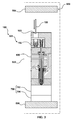
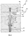
- FIG. 3 depicts an example schematic representation of the mold-tool system ( 100 ).
- the mold-tool system ( 100 ) includes a runner assembly ( 600 ) being configured to provide an access portal ( 103 ).
- the access portal ( 103 ) is configured to permit access to an assembly ( 101 ).
- the access portal ( 103 ) is configured to permit access to the assembly ( 101 ) by a removal assembly ( 105 ), so that the assembly ( 101 ) may be removed from the runner assembly ( 600 ) and replaced.
- the assembly ( 101 ) is configured for support in the runner assembly ( 600 ).
- the access portal ( 103 ) is configured to permit access to the assembly ( 101 ) in situ, for the case where the runner assembly ( 600 ) is operatively mounted to the molding system ( 500 ), and several examples are described below for this case (specifically depicted in FIGS. 3 , 6 , 8 ).
- the assembly ( 101 ) includes a position-adjustment assembly ( 102 ).
- the position-adjustment assembly ( 102 ) is configured to interact with a stem-actuation plate ( 606 ), which is depicted in FIG. 4 A .
- the stem-actuation plate ( 606 ) is connected with a stem assembly ( 609 ) of a nozzle assembly ( 620 ), both of which are depicted in FIG. 4 A .
- the position-adjustment assembly ( 102 ) is configured to adjust an amount of protrusion of the stem assembly ( 609 ) relative to a mold assembly ( 700 ).
- the runner assembly ( 600 ) may support actuatable movement of the stem-actuation plate ( 606 ).
- the runner assembly ( 600 ) provides an access portal ( 103 ) that may be configured to permit accessible adjustment to the position-adjustment assembly ( 102 ).
- the runner assembly ( 600 ) may be completely dismounted or disconnected from the stationary platen ( 504 ) and the mold assembly ( 700 ) (shown as being depicted in FIG. 1 ); then, the runner assembly ( 600 ) may be placed on a repair bench, for example, and the access portal ( 103 ) of the runner assembly ( 600 ) may be used to gain access to the position-adjustment assembly ( 102 ).
- the runner assembly ( 600 ) may remain within the molding envelope ( 533 ) defined by an outer perimeter of stationary platen ( 504 ) and the movable platen ( 506 ).
- the runner assembly ( 600 ) may remain connected with the mold assembly ( 700 ), and the runner assembly ( 600 ) may be disconnected form the stationary platen ( 504 ); then, the movable platen ( 506 ) may be translated away from stationary platen ( 504 ) so that the access portal ( 103 ) of the runner assembly ( 600 ) may be used to gain access to the position-adjustment assembly ( 102 ).
- the access portal ( 103 ) is configured to accommodate insertion of a removal assembly ( 105 ) so as to permit replacement, at least in part, of the position-adjustment assembly ( 102 ), so that a different stem-protrusion height may be realized with another position-adjustment assembly.
- FIGS. 3 , 6 , 8 provide several examples of the access portal ( 103 ) that is configured to permit accessible adjustment to the position-adjustment assembly ( 102 ) in situ.
- the meaning of "in situ” is that the runner assembly ( 600 ) remains positioned in the molding envelope ( 533 ) defined by the outer perimeter of stationary platen ( 504 ) and the movable platen ( 506 ) of the molding system ( 500 ), and/or that the runner assembly ( 600 ) may be attached in accordance to any one of the following cases: (i) directly to stationary platen ( 504 ), and indirectly to the movable platen ( 506 ) through the mold assembly ( 700 ).
- FIG. 3 provides an example of "in situ", wherein: (i) the runner assembly ( 600 ) remains positioned in the molding envelope ( 533 ) defined by stationary platen ( 504 ) and the movable platen ( 506 ), (ii) the runner assembly ( 600 ) remains coupled with the mold assembly ( 700 ), (iii) the mold assembly ( 700 ) and the runner assembly ( 600 ) are positioned in a retracted state that may be set apart from the stationary platen ( 504 ), and (iv) the mold assembly ( 700 ) and the runner assembly ( 600 ) remain supported by the movable platen ( 506 ). It will be appreciated that FIGS. 6 and 8 provide other examples of "in situ".
- FIG. 4 A depicts a more detailed view of the mold-tool system ( 100 ).
- FIG. 4 B shows a first example of a first stem protrusion height that may be realized.
- FIG. 5 A depicts a more detailed view of the mold-tool system ( 100 ) having another position-adjustment assembly that may have a different height than that depicted in FIG. 4 A .
- FIG. 5 B depicts a second example of a second stem protrusion height that may be realized, which is a different stem protrusion height that may be realized with the arrangement depicted in FIG. 4 A .
- FIG. 4 A depicts the first example of the arrangement or manner in which the runner assembly ( 600 ) may provide the access portal ( 103 ).
- "in situ" may include (and is not limited to) a backing plate that defines the access portal ( 103 ) that may be configured to permit access to the position-adjustment assembly ( 102 ) by using a removal assembly ( 105 ) without having to disassemble the stem-actuation plate ( 606 ) and the stem assembly ( 609 ).
- FIG. 7 provides the second example of the arrangement in which the runner assembly ( 600 ) may be arranged to provide the access portal ( 103 ).
- FIG. 9 provides the third example of the arrangement in which the runner assembly ( 600 ) may be arranged to provide the access portal ( 103 ).
- the stem-actuation plate ( 606 ) is configured to move the stem assembly ( 609 ) between a melt-flow position and a melt-no flow position at a gate assembly ( 720 ) leading to the mold assembly ( 700 ).
- the position-adjustment assembly ( 102 ) may be configured to adjust amount of protrusion of the stem assembly ( 609 ) relative to the mold assembly ( 700 ) for the case where the stem assembly ( 609 ) is positioned in the melt-no flow position.
- an actuator (not depicted) may be connected with the stem-actuation plate ( 606 ) and the actuator may be configured to actuate movement of the stem-actuation plate ( 606 ) responsive to the actuator receiving an actuation signal.
- the position-adjustment assembly ( 102 ) is accessible and replaceable from a back side of a backing plate ( 602 ) of the runner assembly ( 600 ). This may reduce time to make stem protrusion adjustments since the position-adjustment assembly ( 102 ) may be replaced while the runner assembly ( 600 ) remains within the molding envelope ( 533 ) defined by the stationary platen ( 504 ) and the movable platen ( 506 ), that is, within the in the press, in situ without removing plates of the runner assembly ( 600 ).
- the runner assembly ( 600 ) may include (and is not limited to) the following components and sub assemblies.
- a backing plate ( 602 ) may be configured to be mounted to and connected to stationary platen ( 504 ).
- the backing plate ( 602 ) may define the access portal ( 103 ) that may be configured to provide access to the position-adjustment assembly ( 102 ) and to a removal assembly ( 105 ).
- the removal assembly ( 105 ) may be used to or may be configured to remove the position-adjustment assembly ( 102 ).
- a stemconnector assembly ( 604 ) is configured to connect a stem-actuation plate ( 606 ) to a stem assembly ( 609 ).
- the position-adjustment assembly ( 102 ) may include thread structure that may be configured to threadably engage the stem-actuation plate ( 606 ).
- the stem assembly ( 609 ) extends through a manifold assembly ( 616 ) and through a nozzle assembly ( 620 ).
- the nozzle assembly ( 620 ) may be attached to one side of the manifold assembly ( 616 ).
- a manifold back plate assembly ( 608 ) abuts the backing plate ( 602 ).
- the stem-actuation plate ( 606 ) may be actuatably movable between the backing plate ( 602 ) and the manifold back plate assembly ( 608 ).
- a back-up pad ( 610 ) is placed between the manifold back plate assembly ( 608 ) and the manifold assembly ( 616 ).
- the manifold assembly ( 616 ) defines a melt channel ( 612 ) that may be configured to distribute the melt to the mold assembly ( 700 ) via the nozzle assembly ( 620 ).
- the manifold assembly ( 616 ) may also include a manifold-drop assembly ( 614 ) that may be configured to define part of the melt channel ( 612 ).
- the stem assembly ( 609 ) may extend through the manifold-drop assembly ( 614 ).
- a manifold front plate assembly ( 618 ) abuts and connects with the manifold back plate assembly ( 608 ).
- the manifold assembly ( 616 ) may be positioned and supported between the manifold front plate assembly ( 618 ) and the manifold back plate assembly ( 608 ).
- the nozzle assembly ( 620 ) may be configured to be in selective fluid communication with the mold assembly ( 700 ).
- the stem assembly ( 609 ) may be configured to be positioned between a melt-flow position, which permits the flow of the melt into the mold assembly ( 700 ), and a melt no-flow position in which no melt leaves the nozzle assembly ( 620 ).
- a gate assembly ( 720 ) may be positioned between the manifold front plate assembly ( 618 ) and the mold assembly ( 700 ).
- FIG. 4 B depicts a cross-sectional view of the gate assembly ( 790 ) of FIG. 4 A , in which between the gate assembly ( 790 ) and the stem assembly ( 609 ) there is defined a gatenozzle melt channel ( 792 ).
- the stem assembly ( 609 ) is depicted, in FIG. 4 A , to be in the closed position or no-flow position.
- the stem assembly ( 609 ) is depicted as extending into the mold assembly ( 700 ) by an amount of stem protrusion ( 794 ).
- the amount of stem protrusion ( 794 ) is the amount of height of the position-adjustment assembly ( 102 ) that exists between the stem-actuation plate ( 606 ) and the manifold back plate assembly ( 608 ).
- FIG. 5 A depicts a cross-sectional view of the runner assembly ( 600 ), for the case where the position-adjustment assembly ( 102 ) is configured to displace the stem-actuation plate ( 606 ) further away from the manifold back plate assembly ( 608 ) such that there may be less protrusion of the stem assembly ( 609 ) into the mold assembly ( 700 ), as depicted in FIG. 5B .
- the mechanisms that are used for alignment of the stem-actuation plate ( 606 ) are known and not depicted or described. There are many ways to actuate movement of stem-actuation plate ( 606 ) (such as, pneumatic, electric, etc)
- FIG. 6 depicts a schematic representation of the runner assembly ( 600 ) for the second example of "in situ", in which (i) the runner assembly ( 600 ) remains positioned in an molding envelope ( 533 ) defined by stationary platen ( 504 ) and the movable platen ( 506 ), (ii) the runner assembly ( 600 ) open at the parting line), (iii) part of the mold assembly ( 700 ) is retracted or set apart from the runner assembly ( 600 ) and the stationary platen ( 504 ), and (iv) the mold assembly ( 700 ) remains supported by the movable platen ( 506 ).
- FIG. 7 depicts a detailed cross-sectional view of the runner assembly ( 600 ) of FIG. 6 .
- Fig. 7 provides a more detailed view of the second example of the relationship of the access portal ( 103 ) as provided by the runner assembly ( 600 ).
- the manifold back plate assembly ( 608 ) and the manifold front plate assembly ( 618 ) and the gate assembly ( 790 ) all define the access portal ( 103 ).
- the access portal ( 103 ) may be used, by the removal assembly ( 105 ) to remove and replace the position-adjustment assembly ( 102 ) from the runner assembly ( 600 ).
- FIG. 8 depicts a schematic representation of the runner assembly ( 600 ) for the third example of "in situ", in which: (i) the runner assembly ( 600 ) remains positioned in an molding envelope ( 533 ) defined by stationary platen ( 504 ) and the movable platen ( 506 ), (ii) the runner assembly ( 600 ) remains connected with the mold assembly ( 700 ), (iii) the runner assembly ( 600 ) remains connected with the stationary platen ( 504 ), and (iv) the mold assembly ( 700 ) remains supported by the movable platen ( 506 ).
- FIG. 9 depicts a detailed cross-sectional view of the runner assembly ( 600 ) of FIG. 8 .
- Fig. 9 provides a more detailed view of the third example of the relationship of the access portal ( 103 ) as provided by the runner assembly ( 600 ).
- the manifold back plate assembly ( 608 ) defines the access portal ( 103 ) that may be oriented from a side of the runner assembly ( 600 ) that is not oriented toward stationary platen ( 504 ) and the movable platen ( 506 )., the access portal ( 103 ) may be used, by the removal assembly ( 105 ) to remove the position-adjustment assembly ( 102 ) from the runner assembly ( 600 ).
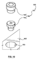
- FIG. 10 depicts a perspective, exploded view (non-assembled state) of a first example of the position-adjustment assembly ( 102 ).
- the position-adjustment assembly ( 102 ) may include (and is not limited to): a retainer assembly ( 150 ), and a spacer element ( 152 ).
- the removal assembly ( 105 ) may be configured to be threadably couplable to the stem-actuation plate ( 606 ).
- the retainer assembly ( 150 ) may be configured to retain the spacer element ( 152 ) in position relative to the stem-actuation plate ( 606 ).
- the spacer element ( 152 ) may have a predetermined height.
- the spacer element ( 152 ) may be replacable with another spacer element that may have a different height than the spacer element ( 152 ), so that the amount of the protrusion of the stem assembly ( 609 ) may be locked.
- the position-adjustment assembly ( 102 ) may be secured by a set screw, or may be threaded, or may include a bolted retainer, a snap ring, etc.
- the position-adjustment assembly ( 102 ) may have a feature that may be configured to allow removal (i.e. a tap, a groove, a hole, etc) of the position-adjustment assembly ( 102 ).
- FIG. 11 depicts a perspective cross sectional view of the position-adjustment assembly ( 102 ) in an assembled state.
- the spacer element ( 152 ) may include a shoulder portion ( 302 ) that may be abutted against the stem-actuation plate ( 606 ). It will be appreciated that the backing plate is not depicted in FIG. 11 . Threads ( 300 ) may be used to connect the retainer assembly ( 150 ) with the stem-actuation plate ( 606 ).
- FIG. 12 depicts a second example of the position-adjustment assembly ( 102 ), in an assembled (installed) state.
- Threads ( 350 ) may be used to connect the retainer assembly ( 150 ) with stem-actuation plate ( 606 ).
- the threads ( 350 ) may provide for continuous height adjustment ( 354 ).
- the position-adjustment assembly ( 102 ) may include (and is not limited to): a single unitary body ( 154 ) configured to: (i) be threadably couplable to the stem-actuation plate ( 606 ), (ii) have a predetermined height, (iii) be replacable with another single unitary body having a different height than the single unitary body ( 154 ), so that the amount of the protrusion of the stem assembly ( 609 ) may be locked.
- FIG. 13 depicts a third example of the position-adjustment assembly ( 102 ), in an exploded perspective view (uninstalled state).
- the position-adjustment assembly ( 102 ) may include (and is not limited to): a spacer member ( 166 ), a pin member ( 160 ) that may have a tool interface ( 168 ) configured to receive an application of torque from a removal assembly ( 105 ).
- a flat portion ( 164 ) may be positioned at an end of the pin member ( 160 ).
- An undercut portion ( 162 ) may be set apart from a top of the pin member ( 160 ). The undercut portion ( 162 ) may be configured to engage the spacer member ( 166 ) so as to facilitate removal of the spacer member ( 166 ) from the stem-actuation plate ( 606 ).
- FIG. 14 depicts the third example of the position-adjustment assembly ( 102 ) of FIG. 13 , in a section view (installed state). Threads ( 360 ) are configured to retain the position-adjustment assembly ( 102 ) and spacer member ( 166 ).
- the stem-actuation plate ( 606 ) may define defines a channel ( 607 ) that may receive the position-adjustment assembly ( 102 ), at least in part. Different spacer heights may change amount of stem protrusion ( 680 ).
Landscapes
- Engineering & Computer Science (AREA)
- Mechanical Engineering (AREA)
- Manufacturing & Machinery (AREA)
- Moulds For Moulding Plastics Or The Like (AREA)
Claims (5)
- Système moule-outil (100), comprenant :un ensemble (101) et un ensemble de canal (600) supportant l'ensemble (101),l'ensemble de canal (600) étant configuré pour fournir une porte d'accès (103) configurée pour permettre l'accès à l'ensemble (101) par un ensemble de retrait (105), de sorte que l'ensemble (101) puisse être retiré de l'ensemble de canal (600) et remplacé,l'ensemble (101) comportant un ensemble de réglage de position (102) qui est configuré pour déplacer une plaque d'actionnement de tige (606) reliée à un ensemble de tige (609) d'un ensemble de buse (620), réglant ainsi un degré de saillie de tige (794) de l'ensemble de tige (609) par rapport à un ensemble de moule (700) ; etl'ensemble de canal (600) supportant le mouvement actionnable de la plaque d'actionnement de tige (606), etla porte d'accès (103) étant configurée pour permettre l'accès à l'ensemble de réglage de position (102),la porte d'accès (103) étant en outre configurée pour permettre l'accès à l'ensemble (101) in situ, dans le cas où l'ensemble de canal (600) est monté de manière fonctionnelle sur un système de moulage (500),caractérisé en ce qu'il comporte in situ une plaque d'appui (602) définissant la porte d'accès (103), et la porte d'accès (103) est configurée pour permettre l'accès à l'ensemble de réglage de position (102) en utilisant l'ensemble de retrait (105) sans avoir à démonter la plaque d'actionnement de tige (606) et l'ensemble de tige (609), et l'ensemble de réglage de position (102) est accessible et remplaçable à partir d'un côté arrière de la plaque d'appui (602) de l'ensemble de canal (600).
- Système moule-outil (100) de la revendication 1, dans lequel la porte d'accès (103) est configurée pour permettre un réglage accessible à l'ensemble de réglage de position (102).
- Système moule-outil (100) de la revendication 1, dans lequel la porte d'accès (103) est configurée pour permettre l'insertion de l'ensemble de retrait (105) de manière à permettre le remplacement, au moins en partie, de l'ensemble de réglage de position (102), de sorte qu'une hauteur de saillie de tige différente puisse être réalisée avec un autre ensemble de réglage de position (102).
- Système moule-outil (100) de la revendication 1, dans lequel la plaque d'actionnement de tige (606) est configurée pour déplacer l'ensemble de tige (609) entre une position d'écoulement de matière fondue et une position de non écoulement de matière fondue au niveau d'un ensemble d'entrée (720) conduisant à l'ensemble de moule (700).
- Système moule-outil (100) de la revendication 1, dans lequel l'ensemble de réglage de position (102) est configuré pour régler un degré de la saillie de l'ensemble de tige (609) par rapport à l'ensemble de moule (700) dans le cas où l'ensemble de tige (609) est positionné dans une position de non écoulement de matière fondue.
Applications Claiming Priority (2)
| Application Number | Priority Date | Filing Date | Title |
|---|---|---|---|
| US201161443735P | 2011-02-17 | 2011-02-17 | |
| PCT/US2012/025330 WO2012112732A2 (fr) | 2011-02-17 | 2012-02-16 | Système d'outil de moulage comprenant un ensemble canal de coulée configuré pour offrir un portail d'accès afin de permettre un accès à un ensemble |
Publications (3)
| Publication Number | Publication Date |
|---|---|
| EP2675603A2 EP2675603A2 (fr) | 2013-12-25 |
| EP2675603A4 EP2675603A4 (fr) | 2014-12-24 |
| EP2675603B1 true EP2675603B1 (fr) | 2016-10-26 |
Family
ID=46673167
Family Applications (1)
| Application Number | Title | Priority Date | Filing Date |
|---|---|---|---|
| EP12747505.1A Not-in-force EP2675603B1 (fr) | 2011-02-17 | 2012-02-16 | Système d'outil de moulage comprenant un ensemble canal de coulée configuré pour offrir un portail d'accès afin de permettre un accès à un ensemble |
Country Status (6)
| Country | Link |
|---|---|
| US (1) | US20130316036A1 (fr) |
| EP (1) | EP2675603B1 (fr) |
| JP (1) | JP5744239B2 (fr) |
| CN (1) | CN103547419B (fr) |
| CA (1) | CA2822645C (fr) |
| WO (1) | WO2012112732A2 (fr) |
Families Citing this family (3)
| Publication number | Priority date | Publication date | Assignee | Title |
|---|---|---|---|---|
| JP2015523250A (ja) | 2012-07-12 | 2015-08-13 | オットー メナー イノヴァツィオン ゲゼルシャフト ゲーエムベーハー | アクティブバルブピンによる係合解除を行う射出成形装置 |
| EP3160709B1 (fr) * | 2014-06-30 | 2019-09-18 | Husky Injection Molding Systems Ltd. | Broche de retenue de ressort pour retenue de tige de soupape |
| EP3785880B1 (fr) * | 2014-10-15 | 2022-05-04 | Inglass S.p.A. | Appareil de moulage par injection de matière plastique |
Family Cites Families (20)
| Publication number | Priority date | Publication date | Assignee | Title |
|---|---|---|---|---|
| US713183A (en) * | 1901-10-16 | 1902-11-11 | John C Wands | Side bearing. |
| US3540329A (en) * | 1969-02-11 | 1970-11-17 | Sanford E Coblitz | Pipe machining tool |
| US5141696A (en) * | 1986-06-30 | 1992-08-25 | Osuna Diaz J M | Method for injection molding using flow adjusting arrangement |
| CA1309819C (fr) * | 1989-06-02 | 1992-11-10 | Jobst Ulrich Gellert | Dispositif de moulage par injection a bague fendue de commande de robinet |
| US5183069A (en) * | 1991-05-17 | 1993-02-02 | Eastman Kodak Company | Adjustable valve stem apparatus for valve gated injection molding devices |
| DE4324275C2 (de) * | 1993-07-20 | 1996-05-02 | Incoe Corp | Pneumatische Steuervorrichtung für Heißkanalnadelventile für Spritzgießwerkzeuge |
| CA2111248C (fr) * | 1993-12-13 | 2002-05-07 | Alex C. Teng | Appareil de moulage a injection a vanne muni d'un ressort a chaque piston |
| US5894025A (en) * | 1997-06-13 | 1999-04-13 | Kona Corporation | Valve pin actuator |
| JP3041255B2 (ja) * | 1997-06-16 | 2000-05-15 | 株式会社型システム | バルブゲート金型 |
| CA2233433C (fr) * | 1998-03-27 | 2007-07-31 | Mold-Masters Limited | Insert de distributeur cylindrique pour moulage par injection et methode connexe |
| JP2000141439A (ja) * | 1998-11-16 | 2000-05-23 | Kobe Steel Ltd | 射出圧縮成形装置 |
| US7131834B2 (en) * | 2002-08-14 | 2006-11-07 | Mold-Masters Ltd. | Valve pin adjustment device |
| CN1496806A (zh) * | 2002-10-18 | 2004-05-19 | 高科技-热通道技术有限责任公司 | 一种打开和关闭注射模具的喷射管嘴的机构 |
| DE20216125U1 (de) * | 2002-10-18 | 2003-01-23 | Heitec-Heisskanaltechnik GmbH, 35099 Burgwald | Vorrichtung zum Öffnen und Schliessen von Einspritzdüsen in einem Spritzgusswerkzeug |
| ATE486706T1 (de) * | 2003-06-23 | 2010-11-15 | Panos Trakas | Verbesserte verstellbare ventilnadelanordnung und verfahren |
| DE202004019328U1 (de) * | 2004-10-20 | 2005-02-24 | Mold-Masters Ltd., Georgetown | Spritzgießvorrichtung mit Ventilnadelverdrehsicherung |
| US7722351B2 (en) * | 2007-10-22 | 2010-05-25 | Mold-Masters (2007) Limited | Injection molding apparatus having magnetic valve pin coupling |
| US20090107646A1 (en) * | 2007-10-31 | 2009-04-30 | Husky Injection Molding Systems Ltd. | Metal-Molding Conduit Assembly of Metal-Molding System |
| DE112009000715T8 (de) * | 2008-03-24 | 2012-05-24 | Husky Injection Molding Systems Ltd. | Sicherheitskonnektor für einen Heisskanal mit einem sich selbst zerstörenden Riegel zur Verriegelung des Ventilschafts und der Betätigungsplatte |
| DE102009048796B4 (de) | 2008-10-10 | 2018-10-25 | Mold-Masters (2007) Limited | Spritzgießvorrichtung mit einer magnetischen Ventilnadelkupplung |
-
2012
- 2012-02-16 US US13/981,652 patent/US20130316036A1/en not_active Abandoned
- 2012-02-16 CN CN201280009215.9A patent/CN103547419B/zh not_active Expired - Fee Related
- 2012-02-16 CA CA2822645A patent/CA2822645C/fr not_active Expired - Fee Related
- 2012-02-16 WO PCT/US2012/025330 patent/WO2012112732A2/fr not_active Ceased
- 2012-02-16 JP JP2013554583A patent/JP5744239B2/ja not_active Expired - Fee Related
- 2012-02-16 EP EP12747505.1A patent/EP2675603B1/fr not_active Not-in-force
Also Published As
| Publication number | Publication date |
|---|---|
| JP2014514972A (ja) | 2014-06-26 |
| JP5744239B2 (ja) | 2015-07-08 |
| EP2675603A2 (fr) | 2013-12-25 |
| CN103547419B (zh) | 2015-11-25 |
| WO2012112732A2 (fr) | 2012-08-23 |
| CA2822645A1 (fr) | 2012-08-23 |
| WO2012112732A3 (fr) | 2013-11-28 |
| US20130316036A1 (en) | 2013-11-28 |
| CA2822645C (fr) | 2015-10-20 |
| EP2675603A4 (fr) | 2014-12-24 |
| CN103547419A (zh) | 2014-01-29 |
Similar Documents
| Publication | Publication Date | Title |
|---|---|---|
| EP2170574B1 (fr) | Empilement de moules de compensation et procédé d'alignement | |
| US8282870B2 (en) | Safety connector for hot runner, having latch destructively interlocking valve stem with actuation plate | |
| CN101873916B (zh) | 用于与模制系统一起使用的补偿模芯以及并入有补偿模芯的模制系统 | |
| US8768504B2 (en) | Method and system for operating an injection molding machine | |
| CN101918193B (zh) | 用于与模制系统一起使用的补偿保持部件及并入有补偿保持部件的模制系统 | |
| CN102285073A (zh) | 具有磁性阀销联接器的注射成型装置 | |
| CA2822645C (fr) | Systeme d'outil de moulage comprenant un ensemble canal de coulee configure pour offrir un portail d'acces afin de permettre un acces a un ensemble | |
| WO2013074741A1 (fr) | Système d'outil de moulage comprenant un ensemble de conformation de tige | |
| US20130287887A1 (en) | Valve-Stem Assembly Removable from Runner System While Valve-Actuator Assembly Remains Connected with Manifold Assembly | |
| US20130171290A1 (en) | Mold-Tool System having Actuator Assembly Including Piston Assembly and Flexible Diaphragm Assembly | |
| US20140127348A1 (en) | Selective Positioning of Nozzle Tip Relative to Mold-Side of Runner System | |
| WO2013032622A1 (fr) | Système d'outil-moule incluant un ensemble verrou conçu pour verrouiller sélectivement une plaque d'actionnement de tige de soupape avec une section mobile de bloc d'attache | |
| WO2012173955A1 (fr) | Système de moulage comprenant un plateau fixe positionné entre un ensemble d'actionnement et une plaque d'actionnement de tige | |
| EP2729291B1 (fr) | Réglage sélectif de la position d'un ensemble buse | |
| WO2013122789A1 (fr) | Système d'outil de moule comprenant un mécanisme de guidage de goupille | |
| US20130017288A1 (en) | Mold-Tool Assembly having Nozzle Assemblies to Provide Resins Molded Adjacently | |
| WO2013044375A1 (fr) | Système d'outil de moulage comportant un ensemble de commande de réduction de pression de matière fondue destiné à réduire sélectivement la pression d'une matière fondue dans une zone de fusion | |
| Wippenbeck | Processing Methods | |
| CA2823393A1 (fr) | Connecteur de securite pour canal chauffant, ayant un verrou destine a verrouiller de maniere destructive la tige de manoeuvre de vanne a la plaque d'actionnement |
Legal Events
| Date | Code | Title | Description |
|---|---|---|---|
| PUAI | Public reference made under article 153(3) epc to a published international application that has entered the european phase |
Free format text: ORIGINAL CODE: 0009012 |
|
| AK | Designated contracting states |
Kind code of ref document: A2 Designated state(s): AL AT BE BG CH CY CZ DE DK EE ES FI FR GB GR HR HU IE IS IT LI LT LU LV MC MK MT NL NO PL PT RO RS SE SI SK SM TR |
|
| AX | Request for extension of the european patent |
Extension state: BA ME |
|
| R17D | Deferred search report published (corrected) |
Effective date: 20131128 |
|
| 17P | Request for examination filed |
Effective date: 20140528 |
|
| RBV | Designated contracting states (corrected) |
Designated state(s): AL AT BE BG CH CY CZ DE DK EE ES FI FR GB GR HR HU IE IS IT LI LT LU LV MC MK MT NL NO PL PT RO RS SE SI SK SM TR |
|
| RIC1 | Information provided on ipc code assigned before grant |
Ipc: B28B 1/00 20060101AFI20140717BHEP |
|
| DAX | Request for extension of the european patent (deleted) | ||
| REG | Reference to a national code |
Ref country code: DE Ref legal event code: R079 Ref document number: 602012024592 Country of ref document: DE Free format text: PREVIOUS MAIN CLASS: B29C0033200000 Ipc: B29C0045280000 |
|
| A4 | Supplementary search report drawn up and despatched |
Effective date: 20141120 |
|
| RIC1 | Information provided on ipc code assigned before grant |
Ipc: B29C 45/28 20060101AFI20141114BHEP |
|
| 17Q | First examination report despatched |
Effective date: 20150825 |
|
| RAP1 | Party data changed (applicant data changed or rights of an application transferred) |
Owner name: HUSKY INJECTION MOLDING SYSTEMS LUXEMBOURG IP DEVE |
|
| GRAP | Despatch of communication of intention to grant a patent |
Free format text: ORIGINAL CODE: EPIDOSNIGR1 |
|
| INTG | Intention to grant announced |
Effective date: 20160331 |
|
| GRAS | Grant fee paid |
Free format text: ORIGINAL CODE: EPIDOSNIGR3 |
|
| GRAA | (expected) grant |
Free format text: ORIGINAL CODE: 0009210 |
|
| RAP1 | Party data changed (applicant data changed or rights of an application transferred) |
Owner name: HUSKY INJECTION MOLDING SYSTEMS LTD. |
|
| AK | Designated contracting states |
Kind code of ref document: B1 Designated state(s): AL AT BE BG CH CY CZ DE DK EE ES FI FR GB GR HR HU IE IS IT LI LT LU LV MC MK MT NL NO PL PT RO RS SE SI SK SM TR |
|
| REG | Reference to a national code |
Ref country code: GB Ref legal event code: FG4D |
|
| REG | Reference to a national code |
Ref country code: CH Ref legal event code: EP |
|
| REG | Reference to a national code |
Ref country code: AT Ref legal event code: REF Ref document number: 839682 Country of ref document: AT Kind code of ref document: T Effective date: 20161115 |
|
| REG | Reference to a national code |
Ref country code: IE Ref legal event code: FG4D |
|
| REG | Reference to a national code |
Ref country code: DE Ref legal event code: R096 Ref document number: 602012024592 Country of ref document: DE |
|
| REG | Reference to a national code |
Ref country code: LT Ref legal event code: MG4D |
|
| PG25 | Lapsed in a contracting state [announced via postgrant information from national office to epo] |
Ref country code: LV Free format text: LAPSE BECAUSE OF FAILURE TO SUBMIT A TRANSLATION OF THE DESCRIPTION OR TO PAY THE FEE WITHIN THE PRESCRIBED TIME-LIMIT Effective date: 20161026 |
|
| REG | Reference to a national code |
Ref country code: NL Ref legal event code: MP Effective date: 20161026 |
|
| REG | Reference to a national code |
Ref country code: AT Ref legal event code: MK05 Ref document number: 839682 Country of ref document: AT Kind code of ref document: T Effective date: 20161026 |
|
| PG25 | Lapsed in a contracting state [announced via postgrant information from national office to epo] |
Ref country code: LT Free format text: LAPSE BECAUSE OF FAILURE TO SUBMIT A TRANSLATION OF THE DESCRIPTION OR TO PAY THE FEE WITHIN THE PRESCRIBED TIME-LIMIT Effective date: 20161026 Ref country code: NO Free format text: LAPSE BECAUSE OF FAILURE TO SUBMIT A TRANSLATION OF THE DESCRIPTION OR TO PAY THE FEE WITHIN THE PRESCRIBED TIME-LIMIT Effective date: 20170126 Ref country code: GR Free format text: LAPSE BECAUSE OF FAILURE TO SUBMIT A TRANSLATION OF THE DESCRIPTION OR TO PAY THE FEE WITHIN THE PRESCRIBED TIME-LIMIT Effective date: 20170127 Ref country code: SE Free format text: LAPSE BECAUSE OF FAILURE TO SUBMIT A TRANSLATION OF THE DESCRIPTION OR TO PAY THE FEE WITHIN THE PRESCRIBED TIME-LIMIT Effective date: 20161026 |
|
| PG25 | Lapsed in a contracting state [announced via postgrant information from national office to epo] |
Ref country code: AT Free format text: LAPSE BECAUSE OF FAILURE TO SUBMIT A TRANSLATION OF THE DESCRIPTION OR TO PAY THE FEE WITHIN THE PRESCRIBED TIME-LIMIT Effective date: 20161026 Ref country code: FI Free format text: LAPSE BECAUSE OF FAILURE TO SUBMIT A TRANSLATION OF THE DESCRIPTION OR TO PAY THE FEE WITHIN THE PRESCRIBED TIME-LIMIT Effective date: 20161026 Ref country code: NL Free format text: LAPSE BECAUSE OF FAILURE TO SUBMIT A TRANSLATION OF THE DESCRIPTION OR TO PAY THE FEE WITHIN THE PRESCRIBED TIME-LIMIT Effective date: 20161026 Ref country code: PL Free format text: LAPSE BECAUSE OF FAILURE TO SUBMIT A TRANSLATION OF THE DESCRIPTION OR TO PAY THE FEE WITHIN THE PRESCRIBED TIME-LIMIT Effective date: 20161026 Ref country code: ES Free format text: LAPSE BECAUSE OF FAILURE TO SUBMIT A TRANSLATION OF THE DESCRIPTION OR TO PAY THE FEE WITHIN THE PRESCRIBED TIME-LIMIT Effective date: 20161026 Ref country code: IS Free format text: LAPSE BECAUSE OF FAILURE TO SUBMIT A TRANSLATION OF THE DESCRIPTION OR TO PAY THE FEE WITHIN THE PRESCRIBED TIME-LIMIT Effective date: 20170226 Ref country code: PT Free format text: LAPSE BECAUSE OF FAILURE TO SUBMIT A TRANSLATION OF THE DESCRIPTION OR TO PAY THE FEE WITHIN THE PRESCRIBED TIME-LIMIT Effective date: 20170227 Ref country code: HR Free format text: LAPSE BECAUSE OF FAILURE TO SUBMIT A TRANSLATION OF THE DESCRIPTION OR TO PAY THE FEE WITHIN THE PRESCRIBED TIME-LIMIT Effective date: 20161026 Ref country code: BE Free format text: LAPSE BECAUSE OF FAILURE TO SUBMIT A TRANSLATION OF THE DESCRIPTION OR TO PAY THE FEE WITHIN THE PRESCRIBED TIME-LIMIT Effective date: 20161026 Ref country code: RS Free format text: LAPSE BECAUSE OF FAILURE TO SUBMIT A TRANSLATION OF THE DESCRIPTION OR TO PAY THE FEE WITHIN THE PRESCRIBED TIME-LIMIT Effective date: 20161026 |
|
| REG | Reference to a national code |
Ref country code: DE Ref legal event code: R097 Ref document number: 602012024592 Country of ref document: DE |
|
| PG25 | Lapsed in a contracting state [announced via postgrant information from national office to epo] |
Ref country code: DK Free format text: LAPSE BECAUSE OF FAILURE TO SUBMIT A TRANSLATION OF THE DESCRIPTION OR TO PAY THE FEE WITHIN THE PRESCRIBED TIME-LIMIT Effective date: 20161026 Ref country code: CZ Free format text: LAPSE BECAUSE OF FAILURE TO SUBMIT A TRANSLATION OF THE DESCRIPTION OR TO PAY THE FEE WITHIN THE PRESCRIBED TIME-LIMIT Effective date: 20161026 Ref country code: EE Free format text: LAPSE BECAUSE OF FAILURE TO SUBMIT A TRANSLATION OF THE DESCRIPTION OR TO PAY THE FEE WITHIN THE PRESCRIBED TIME-LIMIT Effective date: 20161026 Ref country code: RO Free format text: LAPSE BECAUSE OF FAILURE TO SUBMIT A TRANSLATION OF THE DESCRIPTION OR TO PAY THE FEE WITHIN THE PRESCRIBED TIME-LIMIT Effective date: 20161026 Ref country code: SK Free format text: LAPSE BECAUSE OF FAILURE TO SUBMIT A TRANSLATION OF THE DESCRIPTION OR TO PAY THE FEE WITHIN THE PRESCRIBED TIME-LIMIT Effective date: 20161026 |
|
| PG25 | Lapsed in a contracting state [announced via postgrant information from national office to epo] |
Ref country code: BG Free format text: LAPSE BECAUSE OF FAILURE TO SUBMIT A TRANSLATION OF THE DESCRIPTION OR TO PAY THE FEE WITHIN THE PRESCRIBED TIME-LIMIT Effective date: 20170126 Ref country code: SM Free format text: LAPSE BECAUSE OF FAILURE TO SUBMIT A TRANSLATION OF THE DESCRIPTION OR TO PAY THE FEE WITHIN THE PRESCRIBED TIME-LIMIT Effective date: 20161026 Ref country code: IT Free format text: LAPSE BECAUSE OF FAILURE TO SUBMIT A TRANSLATION OF THE DESCRIPTION OR TO PAY THE FEE WITHIN THE PRESCRIBED TIME-LIMIT Effective date: 20161026 |
|
| PLBE | No opposition filed within time limit |
Free format text: ORIGINAL CODE: 0009261 |
|
| REG | Reference to a national code |
Ref country code: DE Ref legal event code: R119 Ref document number: 602012024592 Country of ref document: DE |
|
| STAA | Information on the status of an ep patent application or granted ep patent |
Free format text: STATUS: NO OPPOSITION FILED WITHIN TIME LIMIT |
|
| PG25 | Lapsed in a contracting state [announced via postgrant information from national office to epo] |
Ref country code: MC Free format text: LAPSE BECAUSE OF FAILURE TO SUBMIT A TRANSLATION OF THE DESCRIPTION OR TO PAY THE FEE WITHIN THE PRESCRIBED TIME-LIMIT Effective date: 20161026 |
|
| REG | Reference to a national code |
Ref country code: CH Ref legal event code: PL |
|
| 26N | No opposition filed |
Effective date: 20170727 |
|
| GBPC | Gb: european patent ceased through non-payment of renewal fee |
Effective date: 20170216 |
|
| PG25 | Lapsed in a contracting state [announced via postgrant information from national office to epo] |
Ref country code: CH Free format text: LAPSE BECAUSE OF NON-PAYMENT OF DUE FEES Effective date: 20170228 Ref country code: LI Free format text: LAPSE BECAUSE OF NON-PAYMENT OF DUE FEES Effective date: 20170228 |
|
| REG | Reference to a national code |
Ref country code: IE Ref legal event code: MM4A |
|
| PG25 | Lapsed in a contracting state [announced via postgrant information from national office to epo] |
Ref country code: SI Free format text: LAPSE BECAUSE OF FAILURE TO SUBMIT A TRANSLATION OF THE DESCRIPTION OR TO PAY THE FEE WITHIN THE PRESCRIBED TIME-LIMIT Effective date: 20161026 |
|
| REG | Reference to a national code |
Ref country code: FR Ref legal event code: ST Effective date: 20171031 |
|
| PG25 | Lapsed in a contracting state [announced via postgrant information from national office to epo] |
Ref country code: LU Free format text: LAPSE BECAUSE OF NON-PAYMENT OF DUE FEES Effective date: 20170216 |
|
| PG25 | Lapsed in a contracting state [announced via postgrant information from national office to epo] |
Ref country code: DE Free format text: LAPSE BECAUSE OF NON-PAYMENT OF DUE FEES Effective date: 20170901 Ref country code: FR Free format text: LAPSE BECAUSE OF NON-PAYMENT OF DUE FEES Effective date: 20170228 |
|
| PG25 | Lapsed in a contracting state [announced via postgrant information from national office to epo] |
Ref country code: IE Free format text: LAPSE BECAUSE OF NON-PAYMENT OF DUE FEES Effective date: 20170216 Ref country code: GB Free format text: LAPSE BECAUSE OF NON-PAYMENT OF DUE FEES Effective date: 20170216 |
|
| PG25 | Lapsed in a contracting state [announced via postgrant information from national office to epo] |
Ref country code: MT Free format text: LAPSE BECAUSE OF NON-PAYMENT OF DUE FEES Effective date: 20170216 |
|
| PG25 | Lapsed in a contracting state [announced via postgrant information from national office to epo] |
Ref country code: HU Free format text: LAPSE BECAUSE OF FAILURE TO SUBMIT A TRANSLATION OF THE DESCRIPTION OR TO PAY THE FEE WITHIN THE PRESCRIBED TIME-LIMIT; INVALID AB INITIO Effective date: 20120216 |
|
| PG25 | Lapsed in a contracting state [announced via postgrant information from national office to epo] |
Ref country code: CY Free format text: LAPSE BECAUSE OF NON-PAYMENT OF DUE FEES Effective date: 20161026 |
|
| PG25 | Lapsed in a contracting state [announced via postgrant information from national office to epo] |
Ref country code: MK Free format text: LAPSE BECAUSE OF FAILURE TO SUBMIT A TRANSLATION OF THE DESCRIPTION OR TO PAY THE FEE WITHIN THE PRESCRIBED TIME-LIMIT Effective date: 20161026 |
|
| PG25 | Lapsed in a contracting state [announced via postgrant information from national office to epo] |
Ref country code: TR Free format text: LAPSE BECAUSE OF FAILURE TO SUBMIT A TRANSLATION OF THE DESCRIPTION OR TO PAY THE FEE WITHIN THE PRESCRIBED TIME-LIMIT Effective date: 20161026 |
|
| PG25 | Lapsed in a contracting state [announced via postgrant information from national office to epo] |
Ref country code: AL Free format text: LAPSE BECAUSE OF FAILURE TO SUBMIT A TRANSLATION OF THE DESCRIPTION OR TO PAY THE FEE WITHIN THE PRESCRIBED TIME-LIMIT Effective date: 20161026 |