EP2675689B2 - Caisse de véhicule ferroviaire avec longeron pour la zone de transition entre une paroi latérale et le toit - Google Patents
Caisse de véhicule ferroviaire avec longeron pour la zone de transition entre une paroi latérale et le toit Download PDFInfo
- Publication number
- EP2675689B2 EP2675689B2 EP11708981.3A EP11708981A EP2675689B2 EP 2675689 B2 EP2675689 B2 EP 2675689B2 EP 11708981 A EP11708981 A EP 11708981A EP 2675689 B2 EP2675689 B2 EP 2675689B2
- Authority
- EP
- European Patent Office
- Prior art keywords
- car body
- roof
- attachment point
- protrusion
- section
- Prior art date
- Legal status (The legal status is an assumption and is not a legal conclusion. Google has not performed a legal analysis and makes no representation as to the accuracy of the status listed.)
- Active
Links
Images





Classifications
-
- B—PERFORMING OPERATIONS; TRANSPORTING
- B61—RAILWAYS
- B61D—BODY DETAILS OR KINDS OF RAILWAY VEHICLES
- B61D17/00—Construction details of vehicle bodies
- B61D17/04—Construction details of vehicle bodies with bodies of metal; with composite, e.g. metal and wood body structures
- B61D17/043—Construction details of vehicle bodies with bodies of metal; with composite, e.g. metal and wood body structures connections between superstructure sub-units
-
- B—PERFORMING OPERATIONS; TRANSPORTING
- B61—RAILWAYS
- B61D—BODY DETAILS OR KINDS OF RAILWAY VEHICLES
- B61D17/00—Construction details of vehicle bodies
- B61D17/04—Construction details of vehicle bodies with bodies of metal; with composite, e.g. metal and wood body structures
-
- B—PERFORMING OPERATIONS; TRANSPORTING
- B61—RAILWAYS
- B61D—BODY DETAILS OR KINDS OF RAILWAY VEHICLES
- B61D17/00—Construction details of vehicle bodies
- B61D17/04—Construction details of vehicle bodies with bodies of metal; with composite, e.g. metal and wood body structures
- B61D17/08—Sides
-
- B—PERFORMING OPERATIONS; TRANSPORTING
- B61—RAILWAYS
- B61D—BODY DETAILS OR KINDS OF RAILWAY VEHICLES
- B61D17/00—Construction details of vehicle bodies
- B61D17/04—Construction details of vehicle bodies with bodies of metal; with composite, e.g. metal and wood body structures
- B61D17/10—Floors
-
- B—PERFORMING OPERATIONS; TRANSPORTING
- B61—RAILWAYS
- B61D—BODY DETAILS OR KINDS OF RAILWAY VEHICLES
- B61D17/00—Construction details of vehicle bodies
- B61D17/04—Construction details of vehicle bodies with bodies of metal; with composite, e.g. metal and wood body structures
- B61D17/12—Roofs
Definitions
- the invention relates to a car body of a rail vehicle with a side member for the transition area from a car body side wall to the car body roof of a rail vehicle car body, different car body roof sections can be attached to the side member in a simple manner, and a rail vehicle having such a side member, and also a method for production of a rail vehicle car body with different roof sections.
- Rail vehicle car bodies can have both arched roof areas, also referred to as contour roof areas, and flat roof areas or less steeply rising roof areas.
- the roof level in the flat roof areas is lowered compared to the roof level in the arched roof areas.
- Air conditioning systems, pantographs, energy stores or drive devices, for example, are arranged on the flat roof sections. By arranging such devices on flat roof areas it is avoided that these devices protrude above the level of the arched roof sections, or it is at least achieved that they protrude less far.
- a roof tray for example.
- a roof trough has a horizontal or a substantially horizontal floor, which forms the roof surface, and rising side walls.
- a roof tub can be connected to a contour roof. For example, a rectangular opening is created in a contour roof, into which a roof pan is welded.
- EP 1839989 A2 describes a car body for rail vehicles with a lowered flat roof area.
- a lateral structural body which is arranged at the upper end of the side wall, is cut off in order to create an attachment point for a trough-shaped, lowered flat roof area.
- the disadvantage of such a solution is that part of the lateral structural body has to be cut off in order to make an attachment point for attaching a flat roof area accessible.
- a car body according to the first alternative of the preamble of independent claim 1 is known from EP 0 622 285 A1 .
- Jürgen Schnaas in ZEV + DET Glas, Ann. 123 (1999) 7/8 July / August discloses a top belt for a tram. It consists of two automatically welded profiles in which different functions are integrated, such as a rain gutter. Fastening options for door drives and cable ducts, as well as sealing and adhesive surfaces for the roof, which is made from an aluminum hard foam sandwich.
- CN 2839055Y discloses: a vehicle body structure comprising: a vehicle roof, vehicle windows located on both sides, and a lower wall panel with a vehicle roof side beam provided between the vehicle windows and the vehicle roof.
- a flat upper part for mounting the air-conditioning unit is provided below the vehicle roof.
- a floor frame edge beam, a floor frame center beam and a floor panel are also provided on the lower part of the vehicle body.
- the vehicle roof side beam, the lower wall panel, the floor frame edge beam and the floor frame center beam are made of aluminum material.
- At least one of the components of the vehicle roof, flat top part and base plate identified above is an aluminum honeycomb composite panel.
- U.S. 4,377,058 discloses a curved roof structure for a rail vehicle in which a plurality of roof support webs extend transversely between opposing car side walls at spaced apart intervals. These webs provide support for a variety of large roof panels, generally arranged in end-to-end relationship, which define the roof surface.
- the support webs have outwardly curved or arched shapes between their opposite ends so that the roof panels are similarly bent.
- One object of the present invention is to facilitate the fastening of different roof areas with a different height, and in particular to facilitate the fastening of flat roof areas.
- the invention proposes a car body as indicated in the attached patent claims. Particularly advantageous embodiments of the car body are specified in the subclaims.
- a rail vehicle car body with roof areas of different heights and a method for producing such a rail vehicle car body are also specified.
- the invention relates to a car body with a longitudinal beam or alternatively one according to claim 1.
- the "inside of the car body” corresponds to the inside of the car body of a side wall or an imaginary upward extension of a side wall.
- the term “in the direction of the inside of the car body” does not necessarily mean that an attachment point or a projection described below points into the interior of the vehicle body, because this is at least not the case if a roof section is attached to the attachment point or the projection.
- the term “in the direction of the inside of the car body” does not necessarily mean “in the direction of the interior of the car”. The following examples serve to clarify: If the longitudinal member is arranged over a right side wall in the direction of travel, the term “in the direction of the inside of the car body” means that the second attachment point points to the left in the direction of travel.
- the term "in the direction of the inside of the car body” means that the second attachment point points to the right in the direction of travel.
- first attachment point or a first or second projection (described below), provided that their orientation is defined with reference to a car body inside.
- the side member is a load-bearing element of the car body and runs in the longitudinal direction of the car between the side wall and the roof. In other words, it is arranged in the transition area from the side wall to the roof.
- a carrier according to the invention is also referred to as an upper belt.
- the side member can be part of a car body in an integral construction or intended for a car body in an integral construction.
- the longitudinal member has an attachment point at which a first roof section can be attached and attached, for example an upwardly curved roof section, and another attachment point at which a second roof section, for example a flat roof section, can be attached and attached .
- first roof section and the “second roof section” mean different types of roofs which can be arranged on the side member in succession in the longitudinal direction of the car.
- the difference between the mentioned first roof section and the mentioned second roof section is in particular that the first roof section protrudes upward beyond the second roof section. This means in particular that the first roof section is higher than the second roof section at its highest point.
- the second roof section is provided for attaching devices, for example air conditioning systems, energy stores, drive devices or pantographs, but not the first roof section.
- the cross-sectional shape of a roof or a roof section can vary in its course in the longitudinal direction of the car.
- the longitudinal beam When the longitudinal beam is installed in the car body, it extends in the longitudinal direction of the car body, and preferably over the entire length of the car body.
- the mentioned attachment points for the side wall and the first and second roof sections extend over the entire length of the carrier, preferably over the entire length of the car body.
- the cross-sectional shape of the longitudinal member is essentially the same over the entire length.
- the surfaces that define the attachment points therefore have the same width and possibly the same cross-sectional profile, in particular over the entire length.
- the longitudinal beam according to the invention is made in one piece, for example as an extruded profile, and extends in the longitudinal direction of the car body, preferably from the front end of the car body to the rear end of the car body.
- the longitudinal beam is particularly preferably an extruded profile made of metal, particularly preferably made of aluminum or an aluminum alloy.
- the longitudinal beam is particularly preferred extruded profile with a hollow chamber structure, in particular made of aluminum, wherein the chambers can be separated by walls running in the longitudinal direction.
- the longitudinal member according to the invention is that no mechanical processing has to be carried out on it in order to attach different roof sections.
- the longitudinal beam Over its entire length, preferably the entire length of the car, the longitudinal beam can be designed the same and also remain designed, regardless of whether a first or a second roof section is or will be attached to it.
- the existing, optionally the first and second attachment points are available. After attaching a first roof section to the first attachment point, the unused second attachment point in this section can remain on the carrier, and after attaching a second roof section to the second attachment point, the unused first attachment point in this section can remain on the carrier.
- a car body side wall can be attached to the longitudinal beam and connected to the longitudinal beam.
- a longitudinal member according to the invention is arranged in particular both over the right side wall in the direction of travel and the left side wall of a car body in the direction of travel.
- the longitudinal beams are arranged in mirror image to one another, based on a plane of symmetry arranged between the side walls.
- the various roof sections in particular each extend from longitudinal member to longitudinal member and thus span the space between the side walls.
- the side members are arranged in the transition area from the side wall to the roof of the car body.
- Cross stiffening elements which each extend transversely through the car body and are attached to the second attachment point of a longitudinal member and the second attachment point of another longitudinal member on the other side of the car body, can be attached, for example, to points of the car body, for example by welding, where a first Roof section located and where the second attachment points of the side members on both sides (right and left) of the car body are not used to attach a second roof section.
- a transverse stiffening element extends below a first roof section from the second attachment point of a longitudinal beam on one side of the car body to the second attachment point of a longitudinal beam on the other side of the vehicle body.
- the transverse stiffening element is preferably made of metal, preferably aluminum.
- the first roof section is preferably an upwardly curved roof section.
- a curved roof section is also referred to in this description as a "contour roof” or “arched roof”.
- the term “arched” includes all conceivable radii of curvature and arc shapes. The radius of curvature can also vary and / or the cross-sectional profile can be angled. Looking at a car body in cross section, the contour roof runs e.g. starting from the right (or, conversely, left) side wall upwards, reaches a highest point, a highest area or highest points at any point between the right and left side wall, and runs to the left or, conversely, right) side wall down again.
- the contour roof is preferably mirror-symmetrical to a plane of symmetry assumed halfway between the side walls.
- the second roof section can also be an upwardly curved roof section which, however, in particular does not protrude above the second roof section.
- the first roof section is a roof section with a horizontally extending plateau which is arranged higher than the side edges of the first roof section which are connected to the first attachment point.
- the second roof section can also have a horizontally running plateau which is arranged higher than the side edges of the second roof section, which are attached to the second attachment point, as long as the first roof section protrudes above the second roof section.
- the second roof section is preferably a roof section that runs horizontally or essentially horizontally.
- a roof section is also referred to as a "flat roof” in this description. If you look at a car body in cross section, so the flat roof runs horizontally or essentially horizontally between the right and left side walls.
- the flat roof attached to the second projection of the longitudinal member does not have to run exactly horizontally in every case, which is expressed by the term “essentially”.
- Such a roof can have a slight angle of inclination, in particular of up to 5 ° to the horizontal, starting from both car body side walls in the direction of the center of the car body, whereby the roof can be angled upwards from both car body side walls or downwards from both car body side walls.
- the angled roof areas of such a second roof section meet at the same angle of inclination in the middle of the car body.
- the second roof section is a horizontally running flat roof that extends over the shortest distance from the second attachment point of a longitudinal member on one side of the car body (for example the left side of the car body) to the second attachment point of a longitudinal member on the other side of the car body (e.g. the right side of the car body).
- connections between the roof sections and the longitudinal beam and the side wall and the longitudinal beam are preferably joint connections which require the parts to be joined to be heated. Most preferred is a welded or soldered connection. In principle, however, other joining techniques such as gluing or riveting are also conceivable.
- the attachment points of the side member preferably have profiled surfaces on which the intended roof sections of the car body can be attached.
- One example is a protruding lip.
- the profiled surface is used to attach a first roof section.
- the profiled surface is used to attach a second roof section.
- Roof sections can also have a profiled surface on their edge which is complementary in shape to a profiled surface at a point of attachment.
- the first attachment point has a protruding lip on which a first roof section can be placed and which can be connected to the first roof section by a welded connection.
- the second attachment point has a protruding lip on which a second roof section can be placed and which can be connected to the second roof section by a welded connection.
- the projections and the lower section extend in particular over the entire length of the carrier in the longitudinal direction of the car or at least over a longitudinal section in which various roof sections are attached to the longitudinal carrier.
- the lower portion preferably has a larger cross-sectional area in the cross-section of the side member than each of the projections.
- the width of the lower section is preferably greater than the width of the projections. The width is determined in a direction transverse to the longitudinal direction.
- the lower section is arranged above the side wall in the assembled state of the car body.
- the side wall is attached to the lower section at the third attachment point.
- the third attachment point is preferably at the lower end of the lower section. It is also possible for the side wall and the longitudinal beam to form an integral part.
- the attachment point for the first roof section is located at the end of the first projection and the attachment point for the second roof section is located at the end of the second projection.
- each of the projections can be accessed by welding without the need to separate the projection that is not required.
- the second projection on the longitudinal member can remain unused in a longitudinal section if a first roof section is welded to the first projection in the longitudinal section and vice versa.
- the first projection of the longitudinal member When a second roof section is attached, the first projection of the longitudinal member, pointing vertically upwards or obliquely upwards, remains in place. It can serve as a lateral shield for devices attached to the second roof section, for example air conditioning systems, energy storage devices, drive devices or pantographs, and completely or partially cover such devices or their fastening points. In addition to shielding against effects from the side, such as dust and dirt, the first projection can also function as a privacy screen. If the optical cladding or shielding of devices on a second roof section is not required, the first projection itself can also serve as a fastening point for devices.
- the first projection can serve as a lateral roof delimitation in the area of a second roof section, in particular in the area of a flat roof section, which prevents water from flowing over the roof edge.
- the first projection in the area of a flat roof section can prevent rainwater or water from an air conditioning system installed on the flat roof from running down the car body over the side edges of the roof.
- the first projection itself can also serve to divert water, as explained further below.
- the specially designed longitudinal member described above is preferably an extruded profile made of metal, particularly preferably made of aluminum.
- the longitudinal beam is particularly preferably an extruded profile with a hollow chamber structure, in particular made of aluminum.
- a profile can have an outer (with respect to the interior of the car body) and an inner plate-shaped area, which are connected by additional chamber walls.
- Each projection and the lower section of the longitudinal member according to the invention can have an outer and an inner plate-shaped area which are connected to one another by additional chamber walls.
- the projections can also be formed from a single chamber of a hollow chamber profile. At their end, the projections are preferably closed, for example by a transverse wall.
- the first projection has a drainage channel in its interior.
- the drainage channel is used to divert water from a roof section, preferably from a second roof section.
- the drainage channel preferably extends in the longitudinal direction of the car.
- a drainage channel extending in the longitudinal direction of the car can extend over the entire length of the first projection or only along part of the projection.
- the first projection has at least one inflow opening and at least one outflow opening, between which the drainage channel extends.
- the inflow opening (s) is accessible from the second roof section, for example by being arranged on the side of the projection which faces the second roof section.
- the drainage opening can be arranged at various points, for example at a longitudinal end of the projection, which is arranged at the front end in the direction of travel or at the rear end of a car body.
- a nozzle or a drainage pipe can be attached to the drainage opening.
- the embodiment just described can be combined particularly advantageously with an embodiment in which the first projection is formed from one or more chambers of a hollow chamber profile. Such a chamber then serves as a drainage channel.
- the dimensions of the projections can in principle be freely selected.
- the length of a projection is defined by the length of the side member in the longitudinal direction of the car.
- the depth of a projection corresponds to its extension from a base of the longitudinal member, in particular from the lower section, to its free-standing end.
- the ratio of the width to the depth of the projections can be greater than 1 or it can be less than 1, independently of one another.
- the width of a projection can vary in the depth direction.
- at least one of the projections can taper in the direction of its free end.
- the projections preferably have a profiled surface on which the car body components provided for this purpose can be attached.
- the profiled surface is used to attach a first roof section.
- the profiled surface is used to attach a second roof section.
- the roof sections can have a profiled surface on their edge which is complementary in shape to a profiled surface at the end of an associated projection.
- the first projection has a protruding lip at its free end, on which a first roof section can be placed and which can be connected to the first roof section by a welded connection.
- the first roof section preferably also has a protruding lip at its end, which is connected to the free end of the first projection, which is placed on the lip of the projection on the first projection when the roof section is placed on the lip of the projection, and which in turn extends over a weld connection can be joined to the first projection.
- the first projection can have a recess at the contact point with the lip of the first roof section resting on it, into which the lip of the first roof section is inserted and fits.
- the second projection has a protruding lip on its free end, on which a second roof section can be placed and which can be connected to the second roof section by a welded connection.
- the second roof section preferably also has at its end, which is connected to the free end of the second projection, a protruding lip which, when the roof section is placed on the lip of the projection, is placed on the second projection, and which in turn extends over a weld connection can be joined to the second projection.
- the second projection can have a recess at the contact point with the lip of the second roof section resting on it, into which the lip of the second roof section fits.
- the lower section of the longitudinal member can have, for example, two opposing lips that kink towards each other towards the inside of the lower section, on which two lips protruding from the end of a side wall element abut and with a welded joint between the side wall and the lip at the transition points of the abutting lips Side member can be run.
- the first projection of the longitudinal member can run vertically upwards or obliquely upwards. "At an angle upwards” means that the first projection rises in cross section (transversely to the longitudinal direction of the car body) towards the inside of the car.
- the first projection can run in a straight direction or curved towards its free end.
- the projection can also be straight on one side (inside or outside) and curved on the other side (inside or outside).
- the curvature can connect to the curvature of the contour roof.
- the first projection particularly preferably extends obliquely upwards.
- a preferred angle of the straight extension of the first projection to an imaginary horizontal line is in particular 20 ° to 70 °.
- a first roof section can advantageously be attached to a projection which runs obliquely upward and which runs obliquely downward at its lateral ends.
- the angle of the first projection running obliquely at the top and the angle of the course of the roof section at its end are each identical to the horizontal.
- the second projection faces the inside of the car body. In cross section (transversely to the longitudinal direction of the car body) it runs preferably horizontally or essentially horizontally.
- the second projection can run straight or curved to its free end, the straight shape being preferred.
- essentially horizontal means that it can rise up to an imaginary horizontal line by up to 10 ° or downward by up to 10 °.
- the second projection protrudes beyond the first projection in the horizontal direction towards the inside of the car body.
- the second projection can be accessed particularly well from above in terms of welding technology, because the welding point is not covered by the first projection.
- the depth of the first projection and the depth of the second projection are dimensioned such that an imaginary connecting line from the free end of the first projection to the free end of the second projection forms an angle of 40 ° to 50 ° with the horizontal .
- the free end is defined by its free end. Otherwise there is e.g. an outer wall of a hollow chamber profile.
- the advantage of this embodiment is that the free end of the first projection can be used as a guide for a welding torch when a second roof section is welded to the second projection.
- the welding torch in particular its torch tube, is supported or leaned against the free end of the first projection and the torch opening of the welding torch is aligned with the free end of the second projection on which the second roof section to be joined rests.
- a welding torch aligned in this way can be guided in the longitudinal direction of the carriage along the free end of the first projection and a weld seam can be produced between the free end of the second projection and the adjacent flat roof part.
- the welding torch remains optimally aligned, in particular optimally for creating an overlap seam between the second projection and the second roof section.
- the second projection of the longitudinal member has a fastening means on its underside for fastening an interior lining or other components or assemblies.
- the second projection of the longitudinal member has a double function, namely the function as a connection point for a second roof section and the function of a fastening point, e.g. for interior cladding, for example interior ceilings, or other components, such as e.g. Cable ducts and elements of air conditioning systems.
- a preferred example of a fastening means is a fastening rail, in particular a C-profile rail.
- the fastening means can be a fastening means fastened to the second projection, or the fastening means can be manufactured as an integral part of the second projection, for example as a region of the extruded profile.
- Longitudinal beams described above can be connected to one or more first and / or second roof sections to form a component that is used as an assembly unit or preassembled assembly in the construction of car bodies.
- the invention thus also relates to a component for a rail vehicle car body, having or consisting of the previously described longitudinal beams and one or more first and / or second roof sections attached to the longitudinal beams.
- the invention also relates to a component for a rail vehicle body, comprising a longitudinal beam described above and a side wall connected to the beam.
- a side wall is connected to a separately produced longitudinal member to form an assembly unit or pre-assembled assembly.
- the invention relates to a rail vehicle which has a car body as described above.
- Preferred rail vehicles are metros, local trains, long-distance trains, high-speed trains and trams. Rail vehicles with an integral construction are particularly preferred.
- the invention also relates to a method for producing a rail vehicle car body according to claim 7.
- a longitudinal beam as already described above, including all special and preferred embodiments, can be used in the method.
- Side members according to the invention can be used in step a) of the method as carriers on the right and left side of the car body to the direction of travel.
- a joining device in particular a welding torch, is guided along the second attachment point, in particular a second projection.
- a joining device in particular a welding torch, is guided along the first attachment point, in particular on a first projection.
- the car body to be produced has at least one first roof section and at least one second roof section.
- the arrangement of the roof sections can can in principle be chosen arbitrarily and there can be several first roof sections which alternate with a second or with several second roof sections. It is also possible to connect at least a third roof section to the longitudinal beam at the first or second attachment point.
- flat roof sections are provided at the front and rear car body ends and a contour roof section in between.
- the joining steps of the method are preferably carried out using a joining technique that requires the components to be joined to be heated. A welded connection or a soldered connection is particularly preferred. However, riveted or glued connections are also conceivable.
- An opening can be present between a first roof section and a second roof section if the first roof section does not already have a gable at the transition point.
- openings between first roof sections and second roof sections are closed.
- a gable element such as a sheet metal or a suitably shaped hollow profile, can be inserted into the opening and connected at the upper edge to the edge of the first roof section and at the lower edge to the edge of the second roof section, preferably by a joint connection, in particular by welding .
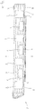
- the Fig. 1a and 1b show a rail vehicle car body 1, the Fig. 1a a view from diagonally above and the Figure 1b shows a view from the side.
- the car body has a head structure which is arranged in the illustration at the right end of the car body and the eye falls on the right side wall 2 in both illustrations.
- the car body has a horizontally running car body roof 3 as a second roof section (flat roof) at the front and rear end ) on. In between there is a curved car body roof 4 (contour roof) as the first roof section. They also show Fig. 1a and 1b Window cutouts 5 and door cutouts 6 in the side wall. An opening 7 is present between the contour roof 4 and the flat roofs 3.
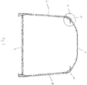
- the Fig. 2 shows a cross section through the car body of FIG Figure 1b along the line II. It is a cross section through the area of the car body in which a contour roof is arranged. Shown are the right car body side wall 2, the left car body side wall 8, the car body floor 9 and the contour roof 4.
- the longitudinal member according to the invention is arranged in the marked section X and is based on the Fig. 3 explained.
- the car body floor 9, the side walls 2, 8, the contour roof 4 and the side members are made of extruded profile parts with a hollow chamber structure.
- the Fig. 3 shows the longitudinal beam 10 according to the invention with an attached right car body side wall 2 and an attached contour roof 4.
- the longitudinal beam 10 is shown as a dark-colored hollow chamber profile to make it easier to distinguish it from adjacent components. This is only a graphic representation and does not mean that the longitudinal beam 10 has to be made of a different material than a contoured roof 4 or a side wall 2. All these parts are preferably made of aluminum.
- the longitudinal support 10, formed from a hollow chamber profile has a first projection 11 pointing obliquely upward and having a free end 12. The free end 12 forms the first attachment point for a first roof section.
- the curved car body roof 4 is welded to the free end 12. Details on the welded connection are given below in Fig. 4 described.
- the longitudinal member 10 has a second projection 13 with a free end 14.
- the free end 14 forms the second attachment point for a second roof section.
- the second projection 13 points horizontally in the direction of the inside of the car body and is arranged below the first projection 11.
- the first projection 11 is formed from a single chamber of a hollow chamber profile and it is tapered in the direction of its free end 12.
- the second projection 13 is formed from two chambers of a hollow chamber profile and tapers in the direction of its free end 14.
- the free end 14 of the second projection 13 is exposed since no flat roof is attached in this area of the car body.
- the outside of the car body is designated with the letter A and the inside of the car body with the letter B.
- the dashed line which is drawn as an extension of the side wall 2, together with the side wall of the car body, forms the boundary line between the inside of the car body B and the outside of the car body A according to the definition of this invention.
- the dashed line corresponds to an imaginary extension of the side wall 2 upwards.
- a corresponding dashed line is also in the Fig. 7 It is shown in the Fig. 3 to see that the second projection 13 protrudes over the first protrusion 11 in the horizontal direction and that it protrudes over the first protrusion in the direction of the inside B of the car body.
- a fastening means 15 in the form of a downwardly open C-rail is provided in the underside of the second projection 13.
- the C-rail is an integral part of the extruded profile.
- a lower section 16 of the longitudinal member 10 is connected to the right side wall 2 at its lower end 17, which is the third attachment point here.
- the lower section 16 has at the lower end two lips 18 which kink inward relative to one another and against which two lips 19 protruding from the end of the side wall 2 rest.
- the lips 18 and 19 are connected to one another by a welded connection, as a result of which the connection from the side wall 2 to the longitudinal beam 10 or its lower section 16 is established.
- the side wall 2 also has a fastening means 20 in the form of a C-rail.
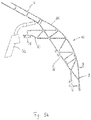
- the Fig. 4 shows an enlarged section from Fig. 3 , in which the attachment point between the first projection 11 of the longitudinal member 10 and the contoured roof 4 is shown. From the Fig. 4 it can be seen that the first projection 11 of the longitudinal member 10 has a protruding lip 30 at its free end 12 on which the contoured roof 4 is placed. At its end 31, the contour roof 4 in turn has a protruding lip 32 which lies on the first projection 11 on the outside of the car body. A gap is formed between the end 31 of the contour roof 4 and the end 12 of the longitudinal member 10 to compensate for manufacturing tolerances.
- the first projection 11 has a recess 33 at the contact point with the lip 32, into which the lip 32 is fitted in order to create a flush transition from the contoured roof 4 to the longitudinal member 10.
- lap welds are carried out in order to join the contoured roof 4 to the free end 12 of the first projection 11 of the longitudinal member 10.
- the creation of such a weld joint is in the Figure 5a and 5b shown.
- the extension of the longitudinal member 10 in the longitudinal direction of the car body is shown in detail, in addition to a section through the longitudinal member 10 and a side wall 2 in the transverse direction.
- the Figure 5b shows only a cross-section.
- the longitudinal member 10 is in one piece or in one piece, ie it extends seamlessly from one end of the car body, which is in the Figure 5a can be seen at the right edge of the picture, to the other end of the car body, which in the view of the Figure 5a is on the left, but is no longer shown in the figure itself.
- the longitudinal beam 10 is arranged in the transition area from the side wall 2 to the roof 4 and is also referred to as the top flange.
- the welding accessibility of the first projection 11 to create a welded connection to the contoured roof 4 is shown.
- the welding torch 50 can be applied from the inside of the car body to create a weld seam.
- the welding technology accessibility to the first projection 11 is given without the second projection 13 having to be separated. If necessary, the welding torch 50 can even be leaned against the second projection 13 and in the longitudinal direction of the car body (in the direction of view of the observer at Figure 5b ) are guided along the second projection 13.
- the Fig. 6 shows a section through a car body 1 along that in FIG Figure 1b shown line II-II. It is a section through an area of the car body 1 in which a flat roof 3 is attached.
- the longitudinal beam 10 according to the invention connects the car body side walls 2, 8 with the flat roof 3. Otherwise, for further explanation of the figure, refer to the explanations for Fig. 2 Be referred to.
- the Fig. 7 shows the section Y from the Fig. 6 in enlargement.
- a side wall 2 is attached to the third end 17, which is the third attachment point here, of the lower section 16, and a flat roof 3 is attached to the free end 14 of the second projection 13.
- the free end 12 of the first projection 11 is exposed and the projection 11 also remains in the flat roof area on the car body.
- the projection 11 protrudes above the level of the flat roof 3 and can serve as a lateral shield for devices (not shown here) attached to the flat roof, such as air conditioning systems.
- the projection can cover the device completely or partially to the outside of the car body A when viewed from the side (from left to right in the picture).
- the Fig. 8 shows an enlarged section from Fig. 7 , in which the connection point from the flat roof 3 to the second projection 13 of the side member 10 is shown in detail.
- the second projection 13 has at its end 14 a protruding lip 40 on which the contour roof 3 is placed. At its end 41, the contour roof 3 has a lip 42 which rests on the second projection 13.
- the second projection 13 has a recess 43 into which the lip 42 of the flat roof 3 fits.
- the free-standing first projection 11 can serve as a guide for a welding torch 50.
- the welding torch 50 is guided along the projection 11 in the longitudinal direction of the car (viewing direction of the observer) in order to create a welded connection between the flat roof 3 and the second projection 13.
- the burner tube 51 of the welding torch 50 is leaned against the edge of the protruding lip 30 at the free end 12 of the first projection 11 and the opening 52 of the burner tube 51 is aligned with the free end 14 of the second projection 13.
- the welding torch By guiding the welding torch along the end of the lip 30 at the free end 12 of the first projection 11 in the longitudinal direction of the carriage, the welding torch remains at the optimum angle, which is around 45 ° here, to create an overlap weld between the flat roof 3 and the second projection 13 aligned.
- the burner nozzle 51 rests on the end of the lip 30.
- the length of the first projection 11, including the lip 30, and the length of the second projection 13 are dimensioned such that an imaginary connecting line from the end of the lip 30 to the free end 14 of the second projection 13 with the horizontal (here for example, the roof line of the flat roof 3) forms an angle of about 45 °.
- the outermost point of the projection 11 is the end 35 of the lip 30.
- the end 12 of the first projection 11 If no lip 30 is provided at the free end 12 of the first projection 11, the end 12, here in the form of a final profile web, itself forms the outermost point and the support point for the Burner nozzle 51.
- the first projection 11 would ideally be dimensioned such that an imaginary connecting line from the free end 12 to the free end 14 forms an angle of 45 ° with the horizontal.
- the Fig. 9 also shows the very good welding accessibility of the connection point from the flat roof 3 to the second projection 13 of the side member, because the second projection 13 protrudes over the first projection 11 in the horizontal direction (horizontally to the left in this illustration).
- Fig. 10 shows the drainage of a flat roof area 3.
- the first projection 11 of a side member 10 has a drainage channel in its interior.
- the first projection 11 is formed from a single chamber of a hollow chamber profile, as for example in FIG Fig. 3 and 4th shown, and this hollow chamber serves as a drainage channel.
- the drainage channel extends in the longitudinal direction of the car and only along part of the projection 11.
- the drainage channel runs from an inflow opening 60 to an outflow opening 61.
- the inflow opening 60 is accessible from a flat roof section 3.
- In the area of the inflow opening are the walls of the hollow profile chamber of the first projection 11 partially removed, whereby a drain niche was created. Areas of the profile hollow chamber of the first projection 11 in which no drainage channel is provided are closed with a plate 64.
- the discharge opening 61 is arranged in the lower area of the hollow profile chamber of the first projection 11 and it is located at the bottom at the longitudinal end 63 of the projection 11 and thus at the end of the car body 1.
- the profile chamber of the first projection is closed at the longitudinal end 63 by a plate 65, so that water flowing off is drained off exclusively through the drain opening 61 pointing downwards. In principle, it would also be conceivable to leave the profile chamber of the first projection open at the side and to drain water through this opening.
- a pipe socket 62 is welded to the first projection 11 at the outflow opening 61. Further piping can be connected to the pipe socket 62 in order to divert draining water specifically to certain positions on the underframe (not shown) of the car body 1, for example to the center of the track bed.
- the direction of flow of the water running off the flat roof section 3 is indicated by arrows. As can be seen from the arrows, water is directed from the flat roof to the end of the car.
Landscapes
- Engineering & Computer Science (AREA)
- Life Sciences & Earth Sciences (AREA)
- Wood Science & Technology (AREA)
- Mechanical Engineering (AREA)
- Body Structure For Vehicles (AREA)
- Butt Welding And Welding Of Specific Article (AREA)
- Train Traffic Observation, Control, And Security (AREA)
- Tires In General (AREA)
Claims (9)
- Caisse de véhicule d'un véhicule ferroviaire, présentant
un longeron (10) réalisé d'un seul tenant, présentant :- un premier point d'attache (12) pointant, en position de montage, de manière perpendiculaire vers le haut ou de manière oblique vers le haut en direction du côté intérieur de caisse de véhicule,- un deuxième point d'attache (14) pointant, en position de montage, en direction du côté intérieur de caisse de véhicule (B), lequel est disposé sous le premier point d'attache (12),- un troisième point d'attache (17) pointant, en position de montage, vers le bas ou de manière oblique vers le bas, pour une paroi latérale de caisse de véhicule (2, 8), dans laquelle- une première section de toit (4) est installée au niveau du premier point d'attache (12) du longeron (10),caractérisée en ce qu'une deuxième section de toit (3) est installée au niveau du deuxième point d'attache (14) du longeron (10) de sorte que la première section de toit dépasse vers le haut de la deuxième section de toit, et en ce que la première section de toit et la deuxième section de toit sont disposées dans une direction longitudinale de caisse alternativement et successivement sur le longeron,
sachant que le longeron présente :- une section inférieure (16) en position de montage, qui présente le troisième point d'attache (17),- une première partie faisant saillie (11) faisant saillie, en position de montage, de manière perpendiculaire vers le haut ou de manière oblique vers le haut en direction du côté intérieur de caisse de véhicule, pourvue d'une extrémité libre, qui présente le premier point d'attache (12), et- une deuxième partie faisant saillie (13) faisant saillie, en position de montage, en direction du côté intérieur de caisse de véhicule (B), laquelle est disposée sous la première partie faisant saillie et présente une extrémité libre, qui présente le deuxième point d'attache (14),dans le cadre de laquelle la deuxième partie faisant saillie (13) dépasse, en position de montage, dans une direction horizontale de la première partie faisant saillie (11). - Caisse de véhicule selon la revendication 1, dans le cadre de laquelle la profondeur de la première partie faisant saillie et la profondeur de la deuxième partie faisant saillie présentent des valeurs telles qu'une ligne de liaison imaginaire allant de l'extrémité libre de la première partie faisant saillie vers l'extrémité libre de la deuxième partie faisant saillie forme, avec l'horizontale, un angle allant de 40° à 50°.
- Caisse de véhicule selon l'une quelconque des revendications 1 à 2, dans le cadre de laquelle la deuxième partie faisant saillie (13) présente, au niveau de son côté inférieur, un moyen de fixation (15) servant à fixer un habillage intérieur ou d'autres composants ou groupes modulaires.
- Caisse de véhicule selon l'une quelconque des revendications 1 à 3, dans le cadre de laquelle la première partie faisant saillie est formée à partir d'une ou de plusieurs chambres d'un profilé de chambre creuse et où une des chambres forme un canal de drainage.
- Caisse de véhicule selon l'une quelconque des revendications précédentes, dans le cadre de laquelle la première section de toit est une section de toit bombée et où la deuxième section de toit est une section de toit horizontale ou sensiblement horizontale.
- Véhicule ferroviaire, présentant une caisse de véhicule selon l'une quelconque des revendications 1 à 5.
- Procédé servant à fabriquer une caisse de véhicule de véhicule ferroviaire comprenant au moins une première section de toit, ainsi qu'au moins une deuxième section de toit, dans lequel dans le cadre du procédéa) respectivement un longeron (10) d'un seul tenant est disposé au-dessus de la zone de la paroi latérale de caisse de véhicule de droite et au-dessus de la zone de la paroi latérale de caisse de véhicule de gauche d'une caisse de véhicule, lequel longeron présente les éléments suivants :- un premier point d'attache (12) pointant, en position de montage, de manière perpendiculaire vers le haut ou de manière oblique vers le haut en direction du côté intérieur de caisse de véhicule, pour une première section de toit,- un deuxième point d'attache (14) pointant, en position de montage, en direction du côté intérieur de caisse de véhicule, pour une deuxième section de toit, dans lequel le deuxième point d'attache (14) est disposé sous le premier point d'attache (12),- un troisième point d'attache (17) pointant, en position de montage, vers le bas ou de manière oblique vers le bas, pour une paroi latérale de caisse de véhicule,sachant que le longeron présente :- une section inférieure (16) en position de montage, qui présente le troisième point d'attache (17),- une première partie faisant saillie (11) faisant saillie, en position de montage, de manière perpendiculaire vers le haut ou de manière oblique vers le haut en direction du côté intérieur de caisse de véhicule, pourvue d'une extrémité libre, qui présente le premier point d'attache (12), et- une deuxième partie faisant saillie (13) faisant saillie, en position de montage, en direction du côté intérieur de caisse de véhicule (B), laquelle est disposée sous la première partie faisant saillie et présente une extrémité libre, qui présente le deuxième point d'attache (14),dans le cadre de laquelle la deuxième partie faisant saillie (13) dépasse, en position de montage, dans une direction horizontale de la première partie faisant saillie (11),b) une paroi latérale de caisse de véhicule droite et une paroi latérale de caisse de véhicule gauche sont assemblées respectivement aux troisièmes points d'attache (17) des deux longerons (10),c) une ou plusieurs premières sections de toit sont assemblées aux premiers points d'attache (12) des deux longerons (10), etd) une ou plusieurs deuxièmes sections de toit sont assemblées aux deuxièmes points d'attache (14) des deux longerons (10) de sorte que des premières et des deuxièmes sections de toit sont disposées dans une direction longitudinale de caisse, que soit seulement une première ou soit seulement une deuxième section de toit est disposée dans une section longitudinale du longeron (10) et que la première section de toit dépasse vers le haut de la deuxième section de toit.
- Procédé selon la revendication 7, caractérisé en ce que lors de l'assemblage de l'une ou des nombreuses premières sections de toit au premier point d'attache, un dispositif d'assemblage, en particulier un chalumeau de soudage, est guidé le long du deuxième point d'attache.
- Procédé selon la revendication 7 ou 8, caractérisé en ce que lors de l'assemblage de l'une ou des nombreuses deuxièmes sections de toit au deuxième point d'attache, un dispositif d'assemblage, en particulier un chalumeau de soudage, est guidé le long du premier point d'attache.
Priority Applications (1)
| Application Number | Priority Date | Filing Date | Title |
|---|---|---|---|
| PL11708981T PL2675689T5 (pl) | 2011-02-14 | 2011-02-14 | Nadwozie wagonu pojazdu szynowego z belką wzdłużną dla obszaru przejściowego ściany bocznej nadwozia wagonu na dach nadwozia wagonu |
Applications Claiming Priority (1)
| Application Number | Priority Date | Filing Date | Title |
|---|---|---|---|
| PCT/EP2011/000668 WO2012110045A1 (fr) | 2011-02-14 | 2011-02-14 | Longeron pour la zone de transition entre une paroi latérale et le toit d'une caisse de véhicule ferroviaire |
Publications (3)
| Publication Number | Publication Date |
|---|---|
| EP2675689A1 EP2675689A1 (fr) | 2013-12-25 |
| EP2675689B1 EP2675689B1 (fr) | 2016-08-17 |
| EP2675689B2 true EP2675689B2 (fr) | 2020-09-02 |
Family
ID=44625452
Family Applications (1)
| Application Number | Title | Priority Date | Filing Date |
|---|---|---|---|
| EP11708981.3A Active EP2675689B2 (fr) | 2011-02-14 | 2011-02-14 | Caisse de véhicule ferroviaire avec longeron pour la zone de transition entre une paroi latérale et le toit |
Country Status (7)
| Country | Link |
|---|---|
| EP (1) | EP2675689B2 (fr) |
| JP (1) | JP2014506541A (fr) |
| KR (1) | KR20140012668A (fr) |
| CN (1) | CN103370254B (fr) |
| PL (1) | PL2675689T5 (fr) |
| SG (1) | SG192790A1 (fr) |
| WO (1) | WO2012110045A1 (fr) |
Families Citing this family (19)
| Publication number | Priority date | Publication date | Assignee | Title |
|---|---|---|---|---|
| DE102012210994A1 (de) * | 2012-06-27 | 2014-01-02 | Siemens Ag | Wagenkasten |
| SG2014011902A (en) * | 2013-04-09 | 2014-11-27 | Bombardier Transp Gmbh | Roof structure for a vehicle |
| WO2015118571A1 (fr) * | 2014-02-05 | 2015-08-13 | 川崎重工業株式会社 | Carrosserie de véhicule ferroviaire |
| US9440661B2 (en) * | 2014-03-06 | 2016-09-13 | Siemens Industry, Inc. | Integrated ceiling assembly for railcars |
| CN103832443A (zh) * | 2014-03-24 | 2014-06-04 | 唐山轨道客车有限责任公司 | 地铁车辆用车顶结构 |
| CN104709302A (zh) * | 2015-03-23 | 2015-06-17 | 南车南京浦镇车辆有限公司 | 轨道车辆多功能车顶边梁 |
| JP6275082B2 (ja) * | 2015-07-02 | 2018-02-07 | 近畿車輌株式会社 | 鉄道車両 |
| CN105599779A (zh) * | 2016-02-05 | 2016-05-25 | 中车青岛四方机车车辆股份有限公司 | 一种轨道车辆侧墙结构 |
| CN106364499A (zh) * | 2016-09-22 | 2017-02-01 | 中车南京浦镇车辆有限公司 | 车顶雨檐排水结构 |
| JP7025847B2 (ja) * | 2017-04-03 | 2022-02-25 | 川崎車両株式会社 | 鉄道車両構体 |
| CN107717188B (zh) * | 2017-11-03 | 2019-11-22 | 中车青岛四方机车车辆股份有限公司 | 一种轨道车辆侧梁内筋双机协同自动焊接方法 |
| CN111284510A (zh) * | 2018-12-07 | 2020-06-16 | 中车唐山机车车辆有限公司 | 轨道车辆的车体侧墙、车体及轨道车辆 |
| JP7361331B2 (ja) * | 2019-10-15 | 2023-10-16 | 川崎車両株式会社 | 継手構造及び構体、並びに構造体 |
| CN112977504A (zh) * | 2019-12-16 | 2021-06-18 | 中车唐山机车车辆有限公司 | 一种轨道车辆及其边顶板与侧墙板的连接结构和连接方法 |
| CN111688732B (zh) * | 2020-05-06 | 2021-06-08 | 中车青岛四方机车车辆股份有限公司 | 侧顶型材、轨道车辆车体及轨道车辆 |
| CN113306585B (zh) * | 2021-07-02 | 2022-11-08 | 中车株洲电力机车有限公司 | 一种车体结构及轨道车辆 |
| DE102021208471A1 (de) * | 2021-08-04 | 2023-02-09 | Siemens Mobility GmbH | Dachkonstruktion für einen Wagenkasten für ein Schienenfahrzeug |
| DE102024209824A1 (de) * | 2024-10-09 | 2026-04-09 | Siemens Mobility GmbH | Spurgeführtes Fahrzeug des Personentransports |
| CN119190104B (zh) * | 2024-10-18 | 2025-10-10 | 中车青岛四方机车车辆股份有限公司 | 边梁型材及轨道车辆车体 |
Citations (6)
| Publication number | Priority date | Publication date | Assignee | Title |
|---|---|---|---|---|
| US4377058A (en) † | 1980-09-09 | 1983-03-22 | United American Car Co. | Curved hopper car roof |
| DE19606792A1 (de) † | 1996-02-23 | 1997-08-28 | Abb Daimler Benz Transp | Schienenfahrzeug mit Wagenkasten |
| JPH1086820A (ja) † | 1996-09-18 | 1998-04-07 | Hitachi Ltd | 鉄道車両の構体構造 |
| EP1100841A1 (fr) † | 1998-08-07 | 2001-05-23 | General Electric Company | Copolycarbonates de qualite optique contenant des unites polyoxyalkylene carbonate |
| CN2839055Y (zh) † | 2005-09-23 | 2006-11-22 | 北京控股磁悬浮技术发展有限公司 | 车体结构 |
| EP1839989A2 (fr) † | 2006-03-28 | 2007-10-03 | Hitachi, Ltd. | Procédé de fabrication d'un véhicule ferroviaire, et éléments creux utilisés pour le procédé. |
Family Cites Families (7)
| Publication number | Priority date | Publication date | Assignee | Title |
|---|---|---|---|---|
| JPS5357411U (fr) * | 1976-10-20 | 1978-05-16 | ||
| FR2704508B1 (fr) * | 1993-04-28 | 1995-06-02 | Gec Alsthom Transport Sa | Caisse de véhicule ferroviaire allégée. |
| SE503463C2 (sv) * | 1994-11-14 | 1996-06-17 | Dunder Trading I Haparanda Ab | Balk och karosseri |
| JP3658900B2 (ja) * | 1996-12-18 | 2005-06-08 | 株式会社日立製作所 | 鉄道車両の天井部内装装置 |
| JP3720789B2 (ja) * | 2002-04-18 | 2005-11-30 | 川崎重工業株式会社 | 鉄道車両用構体 |
| CN201300852Y (zh) * | 2008-10-31 | 2009-09-02 | 长春轨道客车股份有限公司 | 不锈钢轨道客车车顶空调机组座与侧墙连接机构 |
| JP2012183841A (ja) * | 2011-03-03 | 2012-09-27 | Hitachi Ltd | 鉄道車両構体 |
-
2011
- 2011-02-14 SG SG2013062088A patent/SG192790A1/en unknown
- 2011-02-14 WO PCT/EP2011/000668 patent/WO2012110045A1/fr not_active Ceased
- 2011-02-14 CN CN201180067434.8A patent/CN103370254B/zh active Active
- 2011-02-14 JP JP2013552844A patent/JP2014506541A/ja active Pending
- 2011-02-14 KR KR1020137024397A patent/KR20140012668A/ko not_active Withdrawn
- 2011-02-14 EP EP11708981.3A patent/EP2675689B2/fr active Active
- 2011-02-14 PL PL11708981T patent/PL2675689T5/pl unknown
Patent Citations (6)
| Publication number | Priority date | Publication date | Assignee | Title |
|---|---|---|---|---|
| US4377058A (en) † | 1980-09-09 | 1983-03-22 | United American Car Co. | Curved hopper car roof |
| DE19606792A1 (de) † | 1996-02-23 | 1997-08-28 | Abb Daimler Benz Transp | Schienenfahrzeug mit Wagenkasten |
| JPH1086820A (ja) † | 1996-09-18 | 1998-04-07 | Hitachi Ltd | 鉄道車両の構体構造 |
| EP1100841A1 (fr) † | 1998-08-07 | 2001-05-23 | General Electric Company | Copolycarbonates de qualite optique contenant des unites polyoxyalkylene carbonate |
| CN2839055Y (zh) † | 2005-09-23 | 2006-11-22 | 北京控股磁悬浮技术发展有限公司 | 车体结构 |
| EP1839989A2 (fr) † | 2006-03-28 | 2007-10-03 | Hitachi, Ltd. | Procédé de fabrication d'un véhicule ferroviaire, et éléments creux utilisés pour le procédé. |
Non-Patent Citations (2)
| Title |
|---|
| J. SCHNAAS: "Neue Fertigungsprinzipen zum Vorteil des Kunden", ZEITSCHRIFT FUR EISENBAHNWESEN UND VERKEHRSTECHNIK. DIE EISENBAHNTECHNIK + GLASERS ANNALEN,, vol. 123, no. 7/8, 1999, pages 279 - 287 † |
| Schweizerische Eisenbahnrevue 7-8/1992 † |
Also Published As
| Publication number | Publication date |
|---|---|
| KR20140012668A (ko) | 2014-02-03 |
| EP2675689B1 (fr) | 2016-08-17 |
| SG192790A1 (en) | 2013-09-30 |
| PL2675689T5 (pl) | 2020-11-30 |
| CN103370254B (zh) | 2016-10-12 |
| EP2675689A1 (fr) | 2013-12-25 |
| JP2014506541A (ja) | 2014-03-17 |
| CN103370254A (zh) | 2013-10-23 |
| WO2012110045A1 (fr) | 2012-08-23 |
| PL2675689T3 (pl) | 2017-05-31 |
Similar Documents
| Publication | Publication Date | Title |
|---|---|---|
| EP2675689B2 (fr) | Caisse de véhicule ferroviaire avec longeron pour la zone de transition entre une paroi latérale et le toit | |
| DE10108287B4 (de) | Karosseriestruktur | |
| EP0778194B1 (fr) | Véhicule, spécialement véhicule routier ou ferroviaire, comportant une ossature | |
| EP0608761B1 (fr) | Structure de caisse de voiture, notamment ferroviaire | |
| EP2555957B1 (fr) | Paroi extérieure pour une carrosserie de véhicule sur rail et son procédé de fabrication | |
| DE60111600T2 (de) | Wagenkasten eines Schienenfahrzeugs | |
| EP2704938B1 (fr) | Caisse de véhicule ferroviaire et son procédé de fabrication | |
| EP2619063B2 (fr) | Caisse pour véhicule sur rails comportant un dispositif de fixation d'attelage et procédé de production correspondant | |
| DE19606792A1 (de) | Schienenfahrzeug mit Wagenkasten | |
| DE69323638T2 (de) | Aufbau eines Wagenkastens | |
| EP2165906B1 (fr) | Caisse de véhicule ferroviaire et son procédé de fabrication | |
| DE3222419C2 (de) | Dachaufbau für Kraftfahrzeuge mit Schiebedach, insbesondere Personenkraftwagen | |
| DE69021113T2 (de) | Eisenbahnpersonenwagenkasten und dessen Herstellungsverfahren. | |
| EP2559609B1 (fr) | Cadre de renfort et procédé de mise en place d'un cadre de renfort dans une carrosserie de véhicule | |
| EP4341145B1 (fr) | Composant de grande dimension pour véhicule ferroviaire | |
| DE10302756B4 (de) | Tragstruktur für eine Kraftwagenkarosserie | |
| EP4186771B1 (fr) | Véhiucle comprenant un soufflet pourvu de canal de drainage | |
| DE10253396A1 (de) | Glasscheiben-Führungsvorrichtung für eine Fahrzeugtür | |
| EP2165907A1 (fr) | Carrosserie de caisse de voiture et procédé de rééquipement d'une caisse de voiture | |
| DE19724557B4 (de) | Selbsttragende Fahrzeugkarosserie | |
| EP0647476A1 (fr) | Construction de parois pour une cabine d'une installation de peinture | |
| DE102014214789A1 (de) | Schienenfahrzeugbaueinheit | |
| DE102013211577A1 (de) | Verstärkung eines Rohbautragwerks eines Fahrzeugs | |
| EP0861181B1 (fr) | Wagon a marchandises ferme | |
| DE9320494U1 (de) | Wagenkastenaufbau für Eisenbahnwagen zur Personenbeförderung |
Legal Events
| Date | Code | Title | Description |
|---|---|---|---|
| PUAI | Public reference made under article 153(3) epc to a published international application that has entered the european phase |
Free format text: ORIGINAL CODE: 0009012 |
|
| 17P | Request for examination filed |
Effective date: 20130808 |
|
| AK | Designated contracting states |
Kind code of ref document: A1 Designated state(s): AL AT BE BG CH CY CZ DE DK EE ES FI FR GB GR HR HU IE IS IT LI LT LU LV MC MK MT NL NO PL PT RO RS SE SI SK SM TR |
|
| DAX | Request for extension of the european patent (deleted) | ||
| 17Q | First examination report despatched |
Effective date: 20140805 |
|
| GRAP | Despatch of communication of intention to grant a patent |
Free format text: ORIGINAL CODE: EPIDOSNIGR1 |
|
| INTG | Intention to grant announced |
Effective date: 20150513 |
|
| INTG | Intention to grant announced |
Effective date: 20160308 |
|
| GRAS | Grant fee paid |
Free format text: ORIGINAL CODE: EPIDOSNIGR3 |
|
| GRAA | (expected) grant |
Free format text: ORIGINAL CODE: 0009210 |
|
| AK | Designated contracting states |
Kind code of ref document: B1 Designated state(s): AL AT BE BG CH CY CZ DE DK EE ES FI FR GB GR HR HU IE IS IT LI LT LU LV MC MK MT NL NO PL PT RO RS SE SI SK SM TR |
|
| REG | Reference to a national code |
Ref country code: GB Ref legal event code: FG4D Free format text: NOT ENGLISH |
|
| REG | Reference to a national code |
Ref country code: CH Ref legal event code: EP |
|
| REG | Reference to a national code |
Ref country code: IE Ref legal event code: FG4D Free format text: LANGUAGE OF EP DOCUMENT: GERMAN |
|
| REG | Reference to a national code |
Ref country code: AT Ref legal event code: REF Ref document number: 820740 Country of ref document: AT Kind code of ref document: T Effective date: 20160915 |
|
| REG | Reference to a national code |
Ref country code: DE Ref legal event code: R096 Ref document number: 502011010431 Country of ref document: DE |
|
| REG | Reference to a national code |
Ref country code: CH Ref legal event code: NV Representative=s name: PATENTANWALT DIPL.-ING. (UNI.) WOLFGANG HEISEL, CH |
|
| REG | Reference to a national code |
Ref country code: NL Ref legal event code: MP Effective date: 20160817 |
|
| REG | Reference to a national code |
Ref country code: LT Ref legal event code: MG4D |
|
| PG25 | Lapsed in a contracting state [announced via postgrant information from national office to epo] |
Ref country code: FI Free format text: LAPSE BECAUSE OF FAILURE TO SUBMIT A TRANSLATION OF THE DESCRIPTION OR TO PAY THE FEE WITHIN THE PRESCRIBED TIME-LIMIT Effective date: 20160817 Ref country code: LT Free format text: LAPSE BECAUSE OF FAILURE TO SUBMIT A TRANSLATION OF THE DESCRIPTION OR TO PAY THE FEE WITHIN THE PRESCRIBED TIME-LIMIT Effective date: 20160817 Ref country code: HR Free format text: LAPSE BECAUSE OF FAILURE TO SUBMIT A TRANSLATION OF THE DESCRIPTION OR TO PAY THE FEE WITHIN THE PRESCRIBED TIME-LIMIT Effective date: 20160817 Ref country code: NO Free format text: LAPSE BECAUSE OF FAILURE TO SUBMIT A TRANSLATION OF THE DESCRIPTION OR TO PAY THE FEE WITHIN THE PRESCRIBED TIME-LIMIT Effective date: 20161117 Ref country code: RS Free format text: LAPSE BECAUSE OF FAILURE TO SUBMIT A TRANSLATION OF THE DESCRIPTION OR TO PAY THE FEE WITHIN THE PRESCRIBED TIME-LIMIT Effective date: 20160817 Ref country code: IT Free format text: LAPSE BECAUSE OF FAILURE TO SUBMIT A TRANSLATION OF THE DESCRIPTION OR TO PAY THE FEE WITHIN THE PRESCRIBED TIME-LIMIT Effective date: 20160817 Ref country code: NL Free format text: LAPSE BECAUSE OF FAILURE TO SUBMIT A TRANSLATION OF THE DESCRIPTION OR TO PAY THE FEE WITHIN THE PRESCRIBED TIME-LIMIT Effective date: 20160817 |
|
| REG | Reference to a national code |
Ref country code: FR Ref legal event code: PLFP Year of fee payment: 7 |
|
| PG25 | Lapsed in a contracting state [announced via postgrant information from national office to epo] |
Ref country code: SE Free format text: LAPSE BECAUSE OF FAILURE TO SUBMIT A TRANSLATION OF THE DESCRIPTION OR TO PAY THE FEE WITHIN THE PRESCRIBED TIME-LIMIT Effective date: 20160817 Ref country code: PT Free format text: LAPSE BECAUSE OF FAILURE TO SUBMIT A TRANSLATION OF THE DESCRIPTION OR TO PAY THE FEE WITHIN THE PRESCRIBED TIME-LIMIT Effective date: 20161219 Ref country code: ES Free format text: LAPSE BECAUSE OF FAILURE TO SUBMIT A TRANSLATION OF THE DESCRIPTION OR TO PAY THE FEE WITHIN THE PRESCRIBED TIME-LIMIT Effective date: 20160817 Ref country code: GR Free format text: LAPSE BECAUSE OF FAILURE TO SUBMIT A TRANSLATION OF THE DESCRIPTION OR TO PAY THE FEE WITHIN THE PRESCRIBED TIME-LIMIT Effective date: 20161118 Ref country code: LV Free format text: LAPSE BECAUSE OF FAILURE TO SUBMIT A TRANSLATION OF THE DESCRIPTION OR TO PAY THE FEE WITHIN THE PRESCRIBED TIME-LIMIT Effective date: 20160817 |
|
| PG25 | Lapsed in a contracting state [announced via postgrant information from national office to epo] |
Ref country code: RO Free format text: LAPSE BECAUSE OF FAILURE TO SUBMIT A TRANSLATION OF THE DESCRIPTION OR TO PAY THE FEE WITHIN THE PRESCRIBED TIME-LIMIT Effective date: 20160817 Ref country code: EE Free format text: LAPSE BECAUSE OF FAILURE TO SUBMIT A TRANSLATION OF THE DESCRIPTION OR TO PAY THE FEE WITHIN THE PRESCRIBED TIME-LIMIT Effective date: 20160817 |
|
| REG | Reference to a national code |
Ref country code: DE Ref legal event code: R026 Ref document number: 502011010431 Country of ref document: DE |
|
| PLBI | Opposition filed |
Free format text: ORIGINAL CODE: 0009260 |
|
| PLBI | Opposition filed |
Free format text: ORIGINAL CODE: 0009260 |
|
| PLBI | Opposition filed |
Free format text: ORIGINAL CODE: 0009260 |
|
| PG25 | Lapsed in a contracting state [announced via postgrant information from national office to epo] |
Ref country code: DK Free format text: LAPSE BECAUSE OF FAILURE TO SUBMIT A TRANSLATION OF THE DESCRIPTION OR TO PAY THE FEE WITHIN THE PRESCRIBED TIME-LIMIT Effective date: 20160817 Ref country code: BG Free format text: LAPSE BECAUSE OF FAILURE TO SUBMIT A TRANSLATION OF THE DESCRIPTION OR TO PAY THE FEE WITHIN THE PRESCRIBED TIME-LIMIT Effective date: 20161117 Ref country code: CZ Free format text: LAPSE BECAUSE OF FAILURE TO SUBMIT A TRANSLATION OF THE DESCRIPTION OR TO PAY THE FEE WITHIN THE PRESCRIBED TIME-LIMIT Effective date: 20160817 Ref country code: SK Free format text: LAPSE BECAUSE OF FAILURE TO SUBMIT A TRANSLATION OF THE DESCRIPTION OR TO PAY THE FEE WITHIN THE PRESCRIBED TIME-LIMIT Effective date: 20160817 Ref country code: SM Free format text: LAPSE BECAUSE OF FAILURE TO SUBMIT A TRANSLATION OF THE DESCRIPTION OR TO PAY THE FEE WITHIN THE PRESCRIBED TIME-LIMIT Effective date: 20160817 Ref country code: BE Free format text: LAPSE BECAUSE OF NON-PAYMENT OF DUE FEES Effective date: 20170228 |
|
| 26 | Opposition filed |
Opponent name: SIEMENS AKTIENGESELLSCHAFT Effective date: 20170502 |
|
| 26 | Opposition filed |
Opponent name: SIEMENS AG OESTERREICH Effective date: 20170510 |
|
| 26 | Opposition filed |
Opponent name: STADLER RAIL AG Effective date: 20170512 |
|
| PLAX | Notice of opposition and request to file observation + time limit sent |
Free format text: ORIGINAL CODE: EPIDOSNOBS2 |
|
| PG25 | Lapsed in a contracting state [announced via postgrant information from national office to epo] |
Ref country code: SI Free format text: LAPSE BECAUSE OF FAILURE TO SUBMIT A TRANSLATION OF THE DESCRIPTION OR TO PAY THE FEE WITHIN THE PRESCRIBED TIME-LIMIT Effective date: 20160817 |
|
| PG25 | Lapsed in a contracting state [announced via postgrant information from national office to epo] |
Ref country code: MC Free format text: LAPSE BECAUSE OF FAILURE TO SUBMIT A TRANSLATION OF THE DESCRIPTION OR TO PAY THE FEE WITHIN THE PRESCRIBED TIME-LIMIT Effective date: 20160817 |
|
| GBPC | Gb: european patent ceased through non-payment of renewal fee |
Effective date: 20170214 |
|
| PLAB | Opposition data, opponent's data or that of the opponent's representative modified |
Free format text: ORIGINAL CODE: 0009299OPPO |
|
| PLAF | Information modified related to communication of a notice of opposition and request to file observations + time limit |
Free format text: ORIGINAL CODE: EPIDOSCOBS2 |
|
| R26 | Opposition filed (corrected) |
Opponent name: SIEMENS AKTIENGESELLSCHAFT Effective date: 20170502 |
|
| REG | Reference to a national code |
Ref country code: IE Ref legal event code: MM4A |
|
| PG25 | Lapsed in a contracting state [announced via postgrant information from national office to epo] |
Ref country code: LU Free format text: LAPSE BECAUSE OF NON-PAYMENT OF DUE FEES Effective date: 20170214 |
|
| PLBB | Reply of patent proprietor to notice(s) of opposition received |
Free format text: ORIGINAL CODE: EPIDOSNOBS3 |
|
| REG | Reference to a national code |
Ref country code: BE Ref legal event code: MM Effective date: 20170228 |
|
| REG | Reference to a national code |
Ref country code: FR Ref legal event code: PLFP Year of fee payment: 8 |
|
| PG25 | Lapsed in a contracting state [announced via postgrant information from national office to epo] |
Ref country code: GB Free format text: LAPSE BECAUSE OF NON-PAYMENT OF DUE FEES Effective date: 20170214 Ref country code: IE Free format text: LAPSE BECAUSE OF NON-PAYMENT OF DUE FEES Effective date: 20170214 |
|
| PG25 | Lapsed in a contracting state [announced via postgrant information from national office to epo] |
Ref country code: MT Free format text: LAPSE BECAUSE OF FAILURE TO SUBMIT A TRANSLATION OF THE DESCRIPTION OR TO PAY THE FEE WITHIN THE PRESCRIBED TIME-LIMIT Effective date: 20160817 |
|
| PG25 | Lapsed in a contracting state [announced via postgrant information from national office to epo] |
Ref country code: AL Free format text: LAPSE BECAUSE OF FAILURE TO SUBMIT A TRANSLATION OF THE DESCRIPTION OR TO PAY THE FEE WITHIN THE PRESCRIBED TIME-LIMIT Effective date: 20160817 |
|
| PG25 | Lapsed in a contracting state [announced via postgrant information from national office to epo] |
Ref country code: HU Free format text: LAPSE BECAUSE OF FAILURE TO SUBMIT A TRANSLATION OF THE DESCRIPTION OR TO PAY THE FEE WITHIN THE PRESCRIBED TIME-LIMIT; INVALID AB INITIO Effective date: 20110214 |
|
| PLAB | Opposition data, opponent's data or that of the opponent's representative modified |
Free format text: ORIGINAL CODE: 0009299OPPO |
|
| PG25 | Lapsed in a contracting state [announced via postgrant information from national office to epo] |
Ref country code: CY Free format text: LAPSE BECAUSE OF NON-PAYMENT OF DUE FEES Effective date: 20160817 |
|
| R26 | Opposition filed (corrected) |
Opponent name: SIEMENS AKTIENGESELLSCHAFT Effective date: 20170502 |
|
| PG25 | Lapsed in a contracting state [announced via postgrant information from national office to epo] |
Ref country code: MK Free format text: LAPSE BECAUSE OF FAILURE TO SUBMIT A TRANSLATION OF THE DESCRIPTION OR TO PAY THE FEE WITHIN THE PRESCRIBED TIME-LIMIT Effective date: 20160817 |
|
| PG25 | Lapsed in a contracting state [announced via postgrant information from national office to epo] |
Ref country code: TR Free format text: LAPSE BECAUSE OF FAILURE TO SUBMIT A TRANSLATION OF THE DESCRIPTION OR TO PAY THE FEE WITHIN THE PRESCRIBED TIME-LIMIT Effective date: 20160817 |
|
| PG25 | Lapsed in a contracting state [announced via postgrant information from national office to epo] |
Ref country code: IS Free format text: LAPSE BECAUSE OF FAILURE TO SUBMIT A TRANSLATION OF THE DESCRIPTION OR TO PAY THE FEE WITHIN THE PRESCRIBED TIME-LIMIT Effective date: 20161217 |
|
| PUAH | Patent maintained in amended form |
Free format text: ORIGINAL CODE: 0009272 |
|
| STAA | Information on the status of an ep patent application or granted ep patent |
Free format text: STATUS: PATENT MAINTAINED AS AMENDED |
|
| REG | Reference to a national code |
Ref country code: CH Ref legal event code: AELC |
|
| 27A | Patent maintained in amended form |
Effective date: 20200902 |
|
| AK | Designated contracting states |
Kind code of ref document: B2 Designated state(s): AL AT BE BG CH CY CZ DE DK EE ES FI FR GB GR HR HU IE IS IT LI LT LU LV MC MK MT NL NO PL PT RO RS SE SI SK SM TR |
|
| REG | Reference to a national code |
Ref country code: DE Ref legal event code: R102 Ref document number: 502011010431 Country of ref document: DE |
|
| P01 | Opt-out of the competence of the unified patent court (upc) registered |
Effective date: 20230822 |
|
| REG | Reference to a national code |
Ref country code: CH Ref legal event code: U11 Free format text: ST27 STATUS EVENT CODE: U-0-0-U10-U11 (AS PROVIDED BY THE NATIONAL OFFICE) Effective date: 20260301 |
|
| PGFP | Annual fee paid to national office [announced via postgrant information from national office to epo] |
Ref country code: DE Payment date: 20260218 Year of fee payment: 16 |
|
| PGFP | Annual fee paid to national office [announced via postgrant information from national office to epo] |
Ref country code: AT Payment date: 20260219 Year of fee payment: 16 |
|
| PGFP | Annual fee paid to national office [announced via postgrant information from national office to epo] |
Ref country code: FR Payment date: 20260218 Year of fee payment: 16 |
|
| PGFP | Annual fee paid to national office [announced via postgrant information from national office to epo] |
Ref country code: CH Payment date: 20260301 Year of fee payment: 16 |
|
| PGFP | Annual fee paid to national office [announced via postgrant information from national office to epo] |
Ref country code: PL Payment date: 20260209 Year of fee payment: 16 |