EP2675702B1 - Cloison de séparation commune pour réservoirs d'ergol composites - Google Patents
Cloison de séparation commune pour réservoirs d'ergol composites Download PDFInfo
- Publication number
- EP2675702B1 EP2675702B1 EP11808770.9A EP11808770A EP2675702B1 EP 2675702 B1 EP2675702 B1 EP 2675702B1 EP 11808770 A EP11808770 A EP 11808770A EP 2675702 B1 EP2675702 B1 EP 2675702B1
- Authority
- EP
- European Patent Office
- Prior art keywords
- channels
- wall
- layer
- tank
- channel
- Prior art date
- Legal status (The legal status is an assumption and is not a legal conclusion. Google has not performed a legal analysis and makes no representation as to the accuracy of the status listed.)
- Active
Links
Images


Classifications
-
- B—PERFORMING OPERATIONS; TRANSPORTING
- B64—AIRCRAFT; AVIATION; COSMONAUTICS
- B64C—AEROPLANES; HELICOPTERS
- B64C1/00—Fuselages; Constructional features common to fuselages, wings, stabilising surfaces or the like
- B64C1/06—Frames; Stringers; Longerons ; Fuselage sections
- B64C1/10—Bulkheads
-
- B—PERFORMING OPERATIONS; TRANSPORTING
- B32—LAYERED PRODUCTS
- B32B—LAYERED PRODUCTS, i.e. PRODUCTS BUILT-UP OF STRATA OF FLAT OR NON-FLAT, e.g. CELLULAR OR HONEYCOMB, FORM
- B32B3/00—Layered products comprising a layer with external or internal discontinuities or unevennesses, or a layer of non-planar shape; Layered products comprising a layer having particular features of form
- B32B3/26—Layered products comprising a layer with external or internal discontinuities or unevennesses, or a layer of non-planar shape; Layered products comprising a layer having particular features of form characterised by a particular shape of the outline of the cross-section of a continuous layer; characterised by a layer with cavities or internal voids ; characterised by an apertured layer
- B32B3/30—Layered products comprising a layer with external or internal discontinuities or unevennesses, or a layer of non-planar shape; Layered products comprising a layer having particular features of form characterised by a particular shape of the outline of the cross-section of a continuous layer; characterised by a layer with cavities or internal voids ; characterised by an apertured layer characterised by a layer formed with recesses or projections, e.g. hollows, grooves, protuberances, ribs
-
- B—PERFORMING OPERATIONS; TRANSPORTING
- B64—AIRCRAFT; AVIATION; COSMONAUTICS
- B64G—COSMONAUTICS; VEHICLES OR EQUIPMENT THEREFOR
- B64G1/00—Cosmonautic vehicles
- B64G1/10—Artificial satellites; Systems of such satellites; Interplanetary vehicles
-
- B—PERFORMING OPERATIONS; TRANSPORTING
- B64—AIRCRAFT; AVIATION; COSMONAUTICS
- B64G—COSMONAUTICS; VEHICLES OR EQUIPMENT THEREFOR
- B64G1/00—Cosmonautic vehicles
- B64G1/22—Parts of, or equipment specially adapted for fitting in or to, cosmonautic vehicles
- B64G1/40—Arrangements or adaptations of propulsion systems
- B64G1/402—Propellant tanks; Feeding propellants
-
- Y—GENERAL TAGGING OF NEW TECHNOLOGICAL DEVELOPMENTS; GENERAL TAGGING OF CROSS-SECTIONAL TECHNOLOGIES SPANNING OVER SEVERAL SECTIONS OF THE IPC; TECHNICAL SUBJECTS COVERED BY FORMER USPC CROSS-REFERENCE ART COLLECTIONS [XRACs] AND DIGESTS
- Y10—TECHNICAL SUBJECTS COVERED BY FORMER USPC
- Y10T—TECHNICAL SUBJECTS COVERED BY FORMER US CLASSIFICATION
- Y10T428/00—Stock material or miscellaneous articles
- Y10T428/24—Structurally defined web or sheet [e.g., overall dimension, etc.]
- Y10T428/24479—Structurally defined web or sheet [e.g., overall dimension, etc.] including variation in thickness
- Y10T428/24562—Interlaminar spaces
Definitions
- the present disclosure relates generally to rocket propelled vehicles. More particularly, the present disclosure relates to a method and apparatus for a common bulkhead for composite propellant tanks.
- High altitude aircraft, missiles, launch vehicles and satellites are examples of vehicles which may be rocket propelled. These rocket propulsion systems may use liquid or gaseous propellants.
- Liquid propellants may include, for example, without limitation, liquid hydrogen and/or liquid oxygen. Other common combinations include kerosene with liquid oxygen or the storable hypergolic propellants mono-methyl hydrazine with nitrogen tetroxide.
- Propellants are stored in tanks. When more than one tank is present, common walls may be interposed between the tanks. This common wall may also be referred to as a common bulkhead. These types of tanks are often comprised of metal. However, recently, tanks comprised of composite materials have also been used. Tanks comprised of composite materials may result in lower vehicle weights, as compared to metal tanks.
- Two propellants may be stored in two tanks having a common wall. Pressure within the tanks may be different on the two sides of the common wall between the two tanks.
- the common wall may be designed to resist undesired structural changes resulting from this differential pressure and/or other vehicle loads. For many common bulkhead applications, it is desirable that undesired structural changes be reduced and/or prevented with as little weight as possible.
- sandwich construction bulkheads may be comprised of facesheets on either side of a connecting lightweight core. These types of bulkheads are lighter for a given load resistance or more structurally efficient, as compared to a simple monocoque membrane or skin and stiffener construction.
- an apparatus comprises a first structure, a second structure, a first layer, and a second layer.
- the first structure has a first plurality of channels extending towards a number of edges of the first structure.
- the second structure has a second plurality of channels extending towards a number of edges of the second structure.
- a first side of the first structure is connected to a first side of the second structure.
- the first plurality of channels and the second plurality of channels have an orientation with respect to each other.
- the first layer is connected to a second side of the first structure.
- the second layer is connected to a second side of the second structure.
- a method for forming a wall.
- a first structure is placed on a first layer.
- the first structure has a first plurality of channels.
- a second structure is placed on the first structure.
- the second structure has a second plurality of channels.
- the first plurality of channels and the second plurality of channels have an orientation with respect to each other.
- a second layer is placed on the second structure.
- the first layer, the second layer, the first structure, and the second structure are components for the wall. The components are cured to form the wall.
- FIG. 1 an illustration of a spacecraft manufacturing and service method is depicted in accordance with an advantageous embodiment.
- exemplary spacecraft manufacturing and service method 100 may include specification and design 102 of spacecraft 200 in Figure 2 and material procurement 104.
- component and subassembly manufacturing 106 and system integration 108 of spacecraft 200 in Figure 2 may take place. Thereafter, spacecraft 200 in Figure 2 may go through certification and delivery 110 in order to be placed in service 112. While in service 112 by a customer, spacecraft 200 in Figure 2 may be scheduled for routine maintenance and service 114, which may include modification, reconfiguration, refurbishment, and other maintenance or service.
- Each of the processes of spacecraft manufacturing and service method 100 may be performed or carried out by a system integrator, a third party, and/or an operator.
- the operator may be a customer.
- a system integrator may include, without limitation, any number of spacecraft manufacturers and major system subcontractors
- a third party may include, for example, without limitation, any number of vendors, subcontractors, and suppliers
- an operator may be a country, leasing company, military entity, service organization, and other suitable types of operators.
- spacecraft 200 may be produced by spacecraft manufacturing and service method 100 in Figure 1 .
- Spacecraft 200 may include structural system 202 with a plurality of systems 204 and interior 206.
- Structural system 202 is a frame or housing for different systems in spacecraft 200.
- Structural system 202 is similar to the fuselage of an airplane.
- Examples of systems 204 may include, for example, without limitation, one or more of propulsion system 208, electrical system 210, hydraulic system 212, and environmental system 214. Any number of systems may be included. Further, in some implementations, some of the systems may not be needed. For example, when spacecraft 200 takes the form of a launch vehicle, environmental system 214 may be unnecessary.
- Apparatuses and methods embodied herein may be employed during at least one of the stages of spacecraft manufacturing and service method 100 in Figure 1 .
- the phrase "at least one of”, when used with a list of items, means that different combinations of one or more of the listed items may be used and only one of each item in the list may be needed.
- “at least one of item A, item B, and item C” may include, for example, without limitation, item A or item A and item B. This example also may include item A, item B, and item C or item B and item C.
- components or subassemblies produced in component and subassembly manufacturing 106 in Figure 1 may be fabricated or manufactured in a manner similar to components or subassemblies produced while spacecraft 200 is in service 112 in Figure 1 .
- a number of apparatus embodiments, method embodiments, or a combination thereof may be utilized during production stages, such as component and subassembly manufacturing 106 and system integration 108 in Figure 1 as an example, without limitation.
- a number when referring to items, means one or more items.
- "a number of apparatus embodiments" is one or more apparatus embodiments. These embodiments may substantially expedite the assembly of, or reduce the cost of, spacecraft 200.
- advantageous embodiments may be implemented in components in propulsion system 208 in spacecraft 200.
- the advantageous embodiments may be implemented in structures for tanks in propulsion system 208 that hold propellants in spacecraft 200.
- the different advantageous embodiments may be used with any structure within spacecraft 200 in which a common wall is present between structures.
- the different advantageous embodiments recognize and take into account a number of different considerations. For example, without limitation, the different advantageous embodiments recognize and take into account that it would be desirable to increase the strength of a wall between tanks in a manner that does not increase the weight beyond a desired level.
- the different advantageous embodiments recognize and take into account that one manner in which the weight of tanks may be reduced is to fabricate the tanks using composite materials.
- the different advantageous embodiments recognize and take into account that a composite tank may be pressurized and configured to hold a liquid and/or gas.
- the different advantageous embodiments also recognize and take into account that the use of different propellants between two tanks having a common wall may result in pressures that are uneven on either side of the common wall.
- propellants may permeate through composite facesheets that are used in a sandwich construction with a core to form a bulkhead between two tanks.
- mixing rocket propellants with air or an oxidizer may cause an explosion or some other type of undesired event.
- honeycomb sandwich structure This type of structure comprises a core containing cells having a pattern similar to a honeycomb.
- the core is located between two facesheets.
- honeycomb sandwich structure may be lighter, a honeycomb sandwich structure may increase the risk of mixing between the propellants in the two tanks.
- a propellant may permeate or leak through a facesheet into the honeycomb cells. If the propellant leaks from the facesheet on the other side, the two propellants may then mix within the honeycomb cells because of the orientation of the cells with respect to the facesheet.
- This type of structure may be difficult and expensive to produce.
- the different advantageous embodiments recognize and take into account that, with a honeycomb structure, the possibility of a facesheet de-bonding from a honeycomb cell may increase with a smaller surface area for bonding between the facesheets and the edges of the honeycomb cells in the core.
- the different advantageous embodiments recognize and take into account that the chances of de-bonding may increase when the temperature differences between propellants in the two different tanks are great enough. These types of differences in temperatures may occur with cryogenic propellants or a mixture of cryogenic and non-cryogenic propellants.
- the different advantageous embodiments provide a method and apparatus for a common wall used in a tank.
- this common wall may be a wall between two tanks. These tanks may hold a liquid and/or gas.
- the apparatus comprises a first structure, a second structure, a first layer, and a second layer.
- the first structure, the second structure, the first layer, and the second layer form a wall.
- the first structure has a first plurality of channels extending towards a number of edges of the first structure.
- the second structure has a second plurality of channels extending towards the number of edges of the second structure.
- a first side of the first structure is connected to the first side of the second structure.
- the first plurality of channels and the second plurality of channels have an orientation with respect to each other.
- the first layer is connected to a second side of the first structure and the second layer is connected to the second side of the second structure.
- a first component "connected to" a second component means that the first component can be connected directly or indirectly to the second component. In other words, additional components may be present between the first component and the second component. When the first component is directly connected to the second component, no additional components are present between the two components.
- Spacecraft 300 may be an example of spacecraft 200 in Figure 2 .
- spacecraft 300 includes fuel tank system 302.
- Fuel tank system 302 may be in propulsion system 208 in Figure 2 .
- Fuel tank system 302 comprises tank 304 and tank 306.
- tank 304 is configured to hold first fluid 308 in interior 318 of tank 304.
- Tank 306 is configured to hold second fluid 310 in interior 320 of tank 306.
- First fluid 308 and second fluid 310 may take the form of a liquid, a gas, or a combination of the two.
- first fluid 308 and second fluid 310 may be liquid propellants.
- Tank 304 and tank 306 have walls 312. Within walls 312, wall 314 is common wall 316.
- Common wall 316 is a wall shared by tank 304 and tank 306. For example, common wall 316 separates interior 318 of tank 304 from interior 320 of tank 306.
- Common wall 316 may also be referred to as a common bulkhead.
- walls 312 comprise composite materials 322.
- Composite materials 322 reduce the weight of fuel tank system 302 for spacecraft 300 in these illustrative examples. Further, composite materials 322 are selected such that walls 312 have characteristics that allow walls 312 to support number of loads 324. Number of loads 324 may include, for example, pressure 326 generated by first fluid 308 in tank 304 and/or second fluid 310 in tank 306.
- common wall 316 comprises first structure 328, second structure 330, first layer 332, second layer 334, and third layer 336.
- first structure 328, second structure 330, and third layer 336 form core 337 for common wall 316.
- First layer 332 and second layer 334 form facesheets 338 for common wall 316.
- First layer 332, second layer 334, and third layer 336 may be formed using composite materials 322.
- composite materials 322 for third layer 336 may be selected to have a desired level of thermal insulation.
- First side 356 of first structure 328 is connected to first side 354 of second structure 330.
- First layer 332 is connected to second side 358 of first structure 328.
- Second layer 334 is connected to second side 360 of second structure 330.
- third layer 336 may be located between first structure 328 and second structure 330. In this manner, first structure 328 and second structure 330 form core 337 between facesheets 338.
- third layer 336 connects first side 356 of first structure 328 to first side 354 of second structure 330.
- first structure 328 and second structure 330 may be directly connected to each other without intervening components, such as third layer 336.
- additional layers may be present in addition to third layer 336 .
- First structure 328 has first plurality of channels 339 and second structure 330 has second plurality of channels 340.
- First plurality of channels 339 and second plurality of channels 340 may be formed by a first plurality of elongate structures and a second plurality of elongate structures, respectively.
- the first plurality of elongate structures may be, for example, flutes 341.
- the second plurality of elongate structures may be, for example, flutes 343.
- a flute is an elongate structure having a number of walls that form a channel. In these illustrative examples, the channel formed by the flute is open at both ends of the channel.
- first structure 328 comprises flutes 341
- second structure 330 comprises flutes 343.
- Flutes 341 and flutes 343 may be comprised of composite materials, such as laminate composite materials.
- flutes 341 forming first plurality of channels 339 may be arranged substantially parallel to each other such that the channels are substantially parallel to each other.
- flutes 343 forming second plurality of channels 340 may be arranged substantially parallel to each other such that the channels are substantially parallel to each other.
- first plurality of channels 339 may be substantially straight and parallel to each other, while second plurality of channels 340 may be substantially straight and parallel to each other.
- channels within first plurality of channels 339 and/or second plurality of channels 340 may be curved or have some other suitable shape.
- First plurality of channels 339 and second plurality of channels 340 have orientation 346 with respect to each other.
- first plurality of channels 339 and second plurality of channels 340 may be substantially perpendicular or have orientation 346 that is about 90 degrees with respect to each other.
- first plurality of channels 339 may be arranged substantially perpendicular to second plurality of channels 340.
- Orientation 346 may be selected such that desired load 352 can be carried within number of loads 324 on wall 314.
- First plurality of channels 339 in first structure 328 extends towards number of edges 342 of first structure 328.
- the open ends of first plurality of channels 339 are located at or near number of edges 342 of first structure 328.
- Second plurality of channels 340 in second structure 330 extends towards number of edges 344 of second structure 330.
- the open ends of second plurality of channels 340 are located at or near number of edges 344 of second structure 330.
- first plurality of channels 339 and second plurality of channels 340 do not extend toward side 348 and side 350. Instead, at least a portion of these channels may extend toward number of edges 342 and number of edges 344 as described above.
- first structure 328 and second structure 330 may reduce a possibility that first fluid 308 from tank 304 and second fluid 310 from tank 306 may contact each other.
- a portion of first fluid 308 from tank 304 may enter first plurality of channels 339, while a portion of second fluid 310 from tank 306 may enter second plurality of channels 340.
- the orientation of these channels reduces a possibility that these liquids may mix or combine.
- first plurality of channels 339 and second plurality of channels 340 are configured to allow for first fluid 308 that may enter first plurality of channels 339 and/or second fluid 310 that may enter second plurality of channels 340 to be removed from common wall 316 without first fluid 308 and second fluid 310 in these channels combining with each other.
- First fluid 308 and/or second fluid 310 may enter first plurality of channels 339 and/or second plurality of channels 340, respectively, by permeating into common wall 316 through first layer 332 and/or second layer 334, respectively.
- gas purge system 362 is connected to first portion 364 of first plurality of channels 339 and second portion 366 of second plurality of channels 340.
- First portion 364 may be some or all of first plurality of channels 339 and second portion 366 may be some or all of second plurality of channels 340.
- Gas purge system 362 is configured to move gas 368 through first portion 364 of first plurality of channels 339 to remove any of first fluid 308 in first plurality of channels 339.
- gas purge system 362 may move gas 368 from first end 370 of first portion 364 to second end 372 of first portion 364 in first plurality of channels 339.
- gas purge system 362 is configured to move gas 368 from first end 374 in second portion 366 to second end 376 of second portion 366 of second plurality of channels 340 to remove second fluid 310 in second plurality of channels 340.
- the temperature of gas 368 introduced into common wall 316 may be controlled.
- the temperature for gas 368 moved into first plurality of channels 339 may be different than the temperature for gas 368 moved into second plurality of channels 340.
- These temperatures may be controlled to manage the transfer of heat within common wall 316 by first fluid 308 and/or second fluid 310 in common wall 316.
- spacecraft 300 in Figure 3 is not meant to imply physical or architectural limitations to the manner in which different advantageous embodiments may be implemented.
- Other components in addition and/or in place of the ones illustrated may be used. Some components may be unnecessary in some advantageous embodiments.
- the blocks are presented to illustrate some functional components. One or more of these blocks may be combined and/or divided into different blocks when implemented in different advantageous embodiments.
- additional structures in addition to first structure 328 and second structure 330 may be located between first layer 332 and second layer 334 in wall 314.
- a number of additional layers may be located between first structure 328 and second structure 330 in addition to third layer 336.
- third layer 336 may be omitted.
- gas purge system 362 may be omitted depending on the particular implementation.
- gas 368 may be introduced into first plurality of channels 339, while another gas is introduced into second plurality of channels 340.
- gas 368 may be introduced into second plurality of channels 340, while another gas is introduced into first plurality of channels 339.
- FIG. 3 is directed towards spacecraft 300, other advantageous embodiments may be directed towards other types of platforms in which tanks may be used.
- the different advantageous embodiments may be applied to an aircraft, a submarine, a surface ship, a plant, a factory, a manufacturing facility, a storage facility, or some other suitable type of platform in which tanks with common walls may be present that are configured to hold fluids.
- first layer 332, second layer 334, and third layer 336 may be comprised of materials other than composite materials.
- these layers may be comprised of metal, a metal alloy, plastic, and/or other suitable types of materials.
- flutes 341 and flutes 343 are used to form first plurality of channels 339 and second plurality of channels 340, respectively, other types of elongate structures may be used in other illustrative examples.
- tank 304 and tank 306 are part of fuel tank system 302, these tanks may be used to hold other fluids other than liquid propellants or fuel. As one illustrative example, these tanks may be used to hold oxygen for life support or environmental systems in spacecraft 300. In other examples, different types of liquids and/or gases may be held in tank 304 and tank 306.
- launch vehicle 400 is an example of one implementation of spacecraft 300 in Figure 3 .
- Launch vehicle 400 has forward section 402 and aft section 404.
- Launch vehicle 400 may have longitudinal axis 406.
- Launch vehicle 400 is an example of a spacecraft in which fuel tank system 302 in Figure 3 may be implemented.
- Section 408 may be an example of a portion of launch vehicle 400 in which fuel tank system 302 may be found and/or implemented.
- FIG. 5 an illustration of a cut-away side view of a portion of a launch vehicle is depicted in accordance with an advantageous embodiment.
- a cut-away side view of section 408 of launch vehicle 400 taken along lines 5-5 in Figure 4 is depicted. This view allows the interior of launch vehicle 400 to be presented.
- arrow 502 points towards the forward part of launch vehicle 400.
- Arrow 504 points towards the aft portion of launch vehicle 400.
- Tank 506 and tank 508 are formed by walls 510.
- Walls 510 may include dome 512 and dome 514.
- walls 510 also may include wall 516.
- Wall 516 may be a cylindrical wall in these illustrative examples. Wall 516 may be attached to forward skirt 518 and aft skirt 520. In other words, wall 516 may be located between forward skirt 518 and aff skirt 520.
- walls 510 also include wall 522.
- Wall 522 is also referred to as a common bulkhead.
- Wall 522 has a curved shape in which tank 506 is on the convex side of wall 522 and tank 508 is on the concave side of wall 522. This curved shape may also be referred to as a dome.
- walls 510 enclose interior 524 of tank 506 and interior 526 of tank 508. Fluids may be located within interior 524 and interior 526. Interior 524 and interior 526 may be pressurized at different pressures.
- Wall 522 is an example of one implementation for wall 314 in Figure 3 .
- the different structures and layers comprising wall 314 may be implemented in wall 522.
- FIG. 7 A more detailed illustration of wall 522 in section 528 is depicted in Figure 7 below.
- FIG. 8 A more detailed illustration of wall 516 and wall 522 in section 530 is depicted in Figure 8 below.
- wall 522 has side 600 and side 602. Side 600 is on interior 524 of tank 506 in Figure 5 and side 602 is on interior 526 of tank 508 in Figure 5 . In addition, wall 522 has edge 604.
- wall 522 is comprised of first layer 606, second layer 608, third layer 610, first structure 612, and second structure 614.
- First structure 612, second structure 614, and third layer 610 are sandwiched between first layer 606 and second layer 608.
- First structure 612, second structure 614, and third layer 610 form core 616.
- First layer 606 may be facesheet 618 on side 600.
- Second layer 608 may be facesheet 620 on side 602.
- First structure 612 is connected to second structure 614 by third layer 610 in these illustrative examples.
- These layers also may be referred to as laminates depending on the particular implementation.
- First layer 606 is connected to first structure 612 and second layer 608 is connected to second structure 614.
- First structure 612 has channels 622 while second structure 614 has channels 624.
- channels 622 and channels 624 extend towards edge 604 of wall 522 instead of to side 600 and side 602.
- the configuration of channels 622 and channels 624 are also referred to as fluted channels.
- channels 622 and channels 624 are in contrast to the orientation of channels or cells used in a honeycomb structure. Additionally, channels 622 and channels 624 have an orientation with respect to each other. As can be seen in this illustrative example, channels 622 run in a direction that is substantially perpendicular or at about 90 degrees to channels 624. The orientation of channels 622 and 624 are selected to increase loads 626 which may be applied to wall 522. In selecting the orientation of channels 622 and channels 624, the selection is made such that the orthotropic design of these structures may be closer to an isotropic core.
- first layer 606, second layer 608, and third layer 610 are fabricated using composite materials, such as composite materials 322 in Figure 3 .
- Each layer may be fabricated using materials such as, for example, without limitation, fabric, tape, and other suitable materials that may be infused with, or impregnated with, a resin.
- FIG. 7 an illustration of a cross section of a wall is depicted in accordance with an advantageous embodiment.
- wall 522 is seen in a cross sectional view taken along lines 7-7 in Figure 6 .
- a more detailed view of section 530 in Figure 5 is illustrated.
- a more detailed illustration of a portion of first structure 612 and a portion of second structure 614 is depicted in this example.
- channel 700, channel 702, channel 704, channel 706, and channel 708 are examples of some channels that make up channels 622 in first structure 612.
- Channel 710 from channels 624 in second structures 614 is depicted in this view.
- these channels extend through plurality of elongate structures 711 that form first structure 612 and second structure 614.
- plurality of elongate structures 711 includes elongate structures 712, 714, 716, 718, 720, and 722.
- Elongate structures 712, 714, 716, 718, and 720 are examples of elongate structures within first structure 612.
- Elongate structure 722 is an example of an elongate structure located within second structure 614.
- These elongate structures may also be referred to as flutes.
- elongate structures 712, 714, 716, 718, and 720 are arranged substantially perpendicular to elongate structure 722.
- channel 700 extends through elongate structure 712
- channel 702 extends through elongate structure 714
- channel 704 extends through elongate structure 716
- channel 706 extends through elongate structure 718
- channel 708 extends through elongate structure 720.
- channel 710 extends through elongate structure 722.
- each of these channels has a cross section with a shape that is substantially square.
- shape of the cross sections may take other forms.
- shape of the cross sections may be, for example, without limitation, a rectangle, a trapezoid, a hexagon, or some other suitable type of shape.
- channels 622 may be different from the shapes in channels 624.
- channel 700, channel 704, and channel 708 may be square in shape, while channel 702 and channel 706 may be rectangular in shape.
- other variations of shapes may be used depending on the particular implementation.
- first structure 612 and second structure 614 may provide a separation between liquids on side 600 and side 602.
- Third layer 610 may provide additional separation in addition to the elongate structures that form first structure 612 and second structure 614.
- FIG. 8 an illustration of a common wall between tanks is depicted in accordance with an advantageous embodiment.
- a more detailed view of section 530 in Figure 5 is illustrated.
- wall 522 in this view has first layer 606, second layer 608, third layer 610, first structure 612, and second structure 614.
- first structure 612 and second structure 614 are sandwiched between first layer 606 and second layer 608.
- Third layer 610 provides an additional layer of separation between first structure 612 and second structure 614 and connects first structure 612 to second structure 614.
- wall 522 is connected to wall 516.
- Wall 522 may be connected to wall 516 in a number of different ways.
- wall 522 may be bonded to, co-cured with, or otherwise connected to wall 516.
- wall 516 has a similar construction to wall 522. As depicted, wall 516 has first layer 800 and second layer 802. Additionally, wall 516 includes core 804. Core 804 may be formed in a similar fashion to core 616 in Figure 6 .
- wall 516 also has channel 806 and channel 808.
- Channel 808 is connected to at least a portion of channels 622 in first structure 612 of wall 522.
- Channel 806 is connected to at least a portion of channels 624 in structures 614 in wall 522.
- Channel 806 and channel 808 may be part of a purge system. Any fluids that enter channels 622 from interior 526 may be removed from channels 622 through channel 808. Any fluids that enter channels 624 from interior 526 may be removed through channel 806.
- fluids may enter channels 622 and 624 from interior 524 and interior 526.
- fluids may permeate, leak, or otherwise cross first layer 606 and/or second layer 608 into channels 622 and channels 624.
- plurality of elongate structures 711 provides a separation between a liquid that may enter channels 622 from interior 526 from mixing with a liquid that enters channels 624 from interior 524. Additionally, third layer 610 provides an additional separation between liquids that may enter the channels. In this manner, a reduction in the possibility of different liquids mixing with each other may be achieved.
- any liquids that enter the channels may be removed through the purge system as well as channel 806 and channel 808.
- a gas may be introduced into channels 622 through channel 808 and into channels 624 through channel 806 using the purge system. This gas may remove or sweep away the fluids in channels 622 and channels 624 such that the fluids enter channel 806 and channel 808. In this manner, the fluids from interior 524 do not mix or combine with fluids from interior 526 in wall 522.
- purge flow separator 810 provides an additional separation between the channels such that gas to be introduced into channels 622 does not mix or combine with gas to be introduced into channels 624. Further, purge flow separator 810 provides separation between fluids from channels 622 entering channel 808 and fluids from channels 624 entering channel 806. Purge flow separator 810 may be comprised of, for example, without limitation, composite materials.
- wall 522 in Figures 5-8 are not meant to imply physical or architectural limitations to the manner in which wall 522 may be implemented.
- Wall 522 is presented merely as one physical implementation of wall 314 in Figure 3 .
- additional structures in addition to first structure 612 and second structure 614 may be used within core 616.
- third layer 610 may be omitted.
- wall 900 is an example of one implementation for wall 314 in Figure 3 and wall 522 in Figure 5 prior to curing of wall 900.
- Wall 900 comprises first layer 902, second layer 904, third layer 906, first structure 908, and second structure 910.
- elongate structure 912 with channel 914 is depicted.
- first structure 908 elongate structures 915, 916, 918, 920, and 922 are illustrated. These elongate structures have channels 924, 926, 928, 930, and 932 respectively. Elongate structures 912, 915, 916, 918, 920, and 922 may also be referred to as flutes.
- first layer 902, second layer 904 , third layer 906, first structure 908, and second structure 910 are comprised of composite materials.
- these components in wall 900 are in an uncured form.
- the different layers and structures may be made with the same composite materials or different composite materials. Further, the different layers and structures may have different thicknesses depending on the particular implementation.
- the composite materials may take the form of fabric containing fibers.
- a resin may be present or impregnated into the fabric to form a prepreg.
- Layers of fabric may be placed over each other to form each of first layer 902, second layer 904, third layer 906, first structure 908, and second structure 910.
- each of these components may be formed from layers of fabric that are laid over each other.
- the layers of fabric forming a component may have different orientations depending on the particular implementation.
- the fibers may be comprised of at least one of glass fibers, graphite fibers, para-aramid fibers, and other suitable types of fibers.
- the resin may be, for example, at least one of an epoxy, bismaleimide, a polyimide, and other suitable types of resins.
- the composite materials may take the form of tape with resin infused into the tape.
- resin infused into the tape.
- other types of composite materials used to form structures for vehicles may be used depending on the particular implementation.
- first structure 908 and second structure 910 may be comprised of a material different from first layer 902 and second layer 904.
- the elongate structures forming first structure 908 and second structure 910 may be comprised of glass fibers, a combination of glass and graphite fibers, and other suitable types of materials.
- fiberglass may be used.
- Materials for first layer 902 and second layer 904 may be selected as ones that may provide strength and/or may reduce the possibility of liquids moving across these layers. Further, these factors may be used in selecting materials for third layer 906. Additionally, the materials, which may be composite materials, also may be selected as ones that provide thermal insulation.
- third layer 906 may be comprised of different types of materials as compared to first layer 902 and second layer 904.
- Third layer 906 may be comprised of composite materials selected to have a desired level of thermal insulation.
- similar considerations may be made with respect to selecting materials for first layer 902 and second layer 904. These layers also may be selected as having composite materials that provide thermal insulation.
- the materials may be selected to take into account both strength and thermal insulation.
- the selection of material may be made such that the coefficient of thermal expansion has values within a range or a threshold between the different components.
- each elongate structure may be formed separately and then placed onto composite materials for second layer 904. Thereafter, third layer 906 may be placed over the elongate structures. Then, elongate structures for first structure 908 may be placed onto third layer 906. Thereafter, composite materials for first layer 902 may be layed on the elongate structures.
- mandrels 934, 936, 938, 940, and 942 are present within channels 924, 926, 928, 930, and 932 respectively. These mandrels provide a structure to maintain the shape of elongate structures.
- the mandrels may take different forms.
- the mandrels may be comprised of rubber, plastic, wax, and other suitable materials.
- some mandrels may be comprised of a material that may be elastic above a selected temperature. This temperature may be a temperature for when materials are cured. Thereafter, when the temperature is reduced below the selected temperature, the mandrel may recover or return to its original shape. In this manner, the mandrel may be removed when in its elastic form.
- the mandrels may take the form of bladders which may be inflated with a gas or liquid.
- separation films 944, 946, 948, 950, and 952 may be placed around mandrels 934, 936, 938, 940, and 942 within the channels. These separation films may allow for easier removal of the mandrels. Additionally, when mandrels comprised of wax are used, separation films may allow for removal of any wax that may remain in the channels after curing of elongate structures.
- noodles 954, 956, 958, 960, 962, 964, 966, and 968 may be placed in spaces between elongate structures 915, 916, 918, 920, and 922. These noodles may be comprised of composite materials. These noodles may be placed down at the same time as the elongate structures and mandrels are placed onto a layer. After all of the different components for wall 900 have been layed up, these components are cured. Curing may involve the application of heat. In some cases, pressure may be applied in a chamber or through applying a vacuum to a bag placed over one or more of the components in the wall.
- wall 900 in Figure 9 is not meant to imply physical or architectural limitations as to how a wall may be constructed.
- separation films may not be needed.
- a separation film is not needed to remove materials as when mandrels are made of wax.
- wall 1000 is an example of one implementation for wall 314 in Figure 3 .
- a cross section of wall 1000 is depicted.
- channels 1002 in structure 1004 are depicted.
- Structure 1004 is an example of one implementation for first structure 328 and second structure 330 in Figure 3 .
- channels 1002 extend to edge 1006 and edge 1008.
- Channels 1002 at edge 1006 connect to channel 1010.
- Channel 1010 is a channel for gas purge system 362 in Figure 3 .
- Channels 1002 at edge 1008 connect to channel 1012.
- Channel 1012 is also connected to gas purge system 362.
- channel 1010 is formed within wall 1014. Wall 1016 and wall 1018 provide a separation between channel 1010 and channel 1012.
- Arrow 1020 illustrates a flow into opening 1022 in wall 1014.
- Arrow 1024 at opening 1026 illustrates output flow from channel 1010.
- channel 1012 is connected to channel 1010 through channels 1002.
- the flow may enter channel 1012 through opening 1022.
- the flow may then move through channels 1002 into channel 1010.
- the flow then exits through opening 1026 in wall 1014.
- the flow may involve a fluid apart from the fluids that may enter the channels from the tank. This fluid may be a gas or liquid depending on the particular implementation.
- a fluid is selected, the fluid is selected as one that may not react with any liquid that may have entered the channels from a tank.
- this flow may be caused in a number of different ways. For example, a positive pressure may be applied at opening 1022. A negative pressure or vacuum may be applied at opening 1026. In some cases, the pressure may include introducing a fluid.
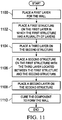
- FIG. 11 a flowchart of a process for forming a wall is depicted in accordance with an advantageous embodiment. The process illustrated in Figure 11 may be used to form wall 314 in Figure 3 .
- the process begins by placing a first layer for the wall (operation 1100 ).
- the placing step may include laying up composite materials, such as fabric, tape, or other suitable types of composite materials, with resin.
- the process places a first structure on the first layer in which the first structure has a plurality of layers (operation 1102 ).
- a first layer, a second layer, a third layer, a first structure, and a second structure are components for the wall.
- the process places a third layer on the second structure (operation 1104 ).
- the process then places a second structure on the first structure with the third layer located between the first structure and the second structure (operation 1106 ).
- the second structure has a second plurality of channels.
- the first plurality of channels and the second plurality of channels have an orientation with respect to each other. In different illustrative examples, the orientation is such that the channels are not parallel to each other.
- the process then places a second layer on the second structure (operation 1108 ).
- the process then cures the component to form the wall (operation 1110 ), with the process terminating thereafter.
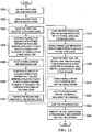
- FIG. 12 an illustration of a flowchart of a process for forming a wall for a launch vehicle is depicted in accordance with an advantageous embodiment.
- the process illustrated in Figure 12 may be implemented to form wall 314 in Figure 3 .
- This process is a more detailed process for the operations described in Figure 11 .
- the process begins by laying up a first layer and a second layer (operation 1200 ).
- the first layer is for an interior of a first tank in which the side of the first layer facing the first tank has a convex shape.
- the second layer is for an interior of a second tank in which the side of the second layer facing the interior of the second tank has a concave shape.
- the first tank and the second tank are configured to hold fluids, such as propellant, in a launch vehicle, such as launch vehicle 400 in Figures 4 and 5 .
- the first layer and the second layer are cured (operation 1202 ).
- the first layer and the second layer form facesheets for a wall, such as wall 522 in Figure 5 .
- the process places the first tank relative to the first layer (operation 1204 ). Thereafter, a plurality of elongate structures, separation films, and mandrels are positioned relative to each other to form a first plurality of channels for a first structure (operation 1205 ). A third layer is placed on the first structure (operation 1206 ). Next, a plurality of elongate structures, separation films, and mandrels are positioned relative to each other to form a second plurality of channels for a second structure on the third layer (operation 1208 ). The first plurality of channels and the second plurality of channels are substantially perpendicular to each other.
- the process positions the second tank relative to the second layer (operation 1210 ).
- the process then cures the first structure and the second structure with the first layer and the second layer (operation 1212 ).
- the process then bonds a purge flow separator for a gas purge system to an edge of the third layer (operation 1214 ).
- the process bonds the first tank, the second tank, and the purge flow separator to a first layer for a cylindrical wall for the launch vehicle using a film adhesive (operation 1216 ).
- the first layer forms the inboard facesheet for the cylindrical wall.
- the cylindrical wall may be, for example, wall 516 in Figure 5 .
- the process forms channels within the cylindrical wall for the purge system (operation 1218 ).
- the process lays up a second layer for the cylindrical wall over the channels (operation 1220).
- the second layer forms the outboard facesheet for the cylindrical wall.
- the process then cures the cylindrical wall (operation 1222 ).
- the cylindrical wall with the first tank, the second tank, and the wall in between the first tank and the second tank form a fuel tank system.
- the process then inspects the fuel tank system ultrasonically and completes the fuel tank system (operation 1224 ), with the processing terminating thereafter.
- each block in the flowchart or block diagrams may represent a module, segment, function, and/or a portion of an operation or step.
- the function or functions noted in the block may occur out of the order noted in the figures.
- two blocks shown in succession may be executed substantially concurrently, or the blocks may sometimes be executed in the reverse order, depending upon the functionality involved.
- other blocks may be added in addition to the illustrated blocks in a flowchart or block diagram.
- operation 1104 may be omitted if a third layer is not needed. In this case, the second structure is placed directly on the first stricture.
- This wall may be a common wall between structures such as tanks in a fuel tank system for a spacecraft.
- the apparatus comprises a first layer of composite materials, a second layer of composite materials, a first structure, and a second structure.
- the first structure has a first plurality of channels extending towards a number of edges of the first structure.
- the second structure has a second plurality of channels extending towards the number of edges of the second structure.
- a first side of the first structure is connected to the first side of the second structure.
- the first plurality of channels and the second plurality of channels have an orientation with respect to each other.
- the first layer of composite materials is connected to a second side of the first structure and the second layer of composite materials is connected to the second side of the second structure.
- the first structure, the second structure, the first layer, and the second layer of composite materials form a wall.
- the load that may be carried by the wall may be increased.
- the load that can be carried also may be increased through a selection of composite materials and a thickness of the different layers and structures.
- the wall in the different illustrative examples may carry a higher load as compared to other types of walls having a similar weight.
- increased loads may be carried in a wall that may reduce the weight as compared to other types of walls that may be used to carry substantially the same loads.
Landscapes
- Engineering & Computer Science (AREA)
- Aviation & Aerospace Engineering (AREA)
- Remote Sensing (AREA)
- Mechanical Engineering (AREA)
- Physics & Mathematics (AREA)
- Astronomy & Astrophysics (AREA)
- General Physics & Mathematics (AREA)
- Chemical & Material Sciences (AREA)
- Combustion & Propulsion (AREA)
- Laminated Bodies (AREA)
Claims (13)
- Cloison pour véhicule de lancement, comprenant :une première structure (328) présentant une première pluralité de canaux (339) qui s'étendent vers une multiplicité de bords (342) de la première structure (328) ; caractérisée en ce qu'elle comprendune deuxième structure (330) présentant une deuxième pluralité de canaux (340) qui s'étendent vers une multiplicité de bords (342) de la deuxième structure (330), une première face (356) de la première structure (328) étant reliée à une première face (354) de la deuxième structure (330), et la première pluralité de canaux (339) et la deuxième pluralité de canaux (340) présentant une orientation en rapport l'une avec l'autre ;une première couche (332) reliée à une deuxième face (358) de la première structure (328) ; etune deuxième couche (334) reliée à une deuxième face (360) de la deuxième structure (330) ; et comprenant en outreun système de purge de gaz (362) relié à une première partie (364) de la première pluralité de canaux (339) et à une deuxième partie (366) de la deuxième pluralité de canaux (340), le système de purge de gaz (362) étant configuré pour faire passer le gaz d'un premier bord de la première partie de la première pluralité de canaux (339) vers un deuxième bord de la première partie de la première pluralité de canaux (339) et pour faire passer le gaz d'un premier bord de la deuxième partie de la deuxième pluralité de canaux (340) vers un deuxième bord de la deuxième partie de la deuxième pluralité de canaux (340).
- Cloison selon la revendication 1, dans laquelle la première structure (328), la deuxième structure (330), la première couche (332) et la deuxième couche (334) forment une cloison (316), et dans laquelle la première pluralité de canaux (339) et la deuxième pluralité de canaux (340) présentent une orientation en rapport l'une avec l'autre qui est telle que la cloison est configurée pour porter une charge souhaitée.
- Cloison selon les revendications 1 et 2, dans laquelle l'orientation de la première pluralité de canaux (339) et de la deuxième pluralité de canaux (340) en rapport l'une avec l'autre est d'environ quatre-vingt-dix degrés.
- Cloison selon l'une quelconque des revendications 1 à 3, comprenant en outre :une troisième couche (336) située entre la première structure (328) et la deuxième structure (330), la troisième couche reliant la première face (354) de la deuxième structure (330) à la première face de la première structure (328).
- Cloison selon l'une quelconque des revendications 1 à 4, dans laquelle la première structure (328) comprend une première pluralité de structures allongées et la deuxième structure (330) comprend une deuxième pluralité de structures allongées.
- Cloison selon l'une quelconque des revendications 1 à 5, dans laquelle la première pluralité de canaux (339) et la deuxième pluralité de canaux (340) présentent une section transversale dont la forme est celle d'un carré, d'un rectangle, d'un trapèze et/ou d'un hexagone.
- Cloison selon la revendication 4, dans laquelle la troisième couche (336) se compose d'un matériau composite choisi pour présenter un niveau souhaité d'isolation thermique.
- Cloison selon la revendication 4, dans laquelle la première structure (328), la deuxième structure (330), la première couche, la deuxième couche et la troisième couche (336) forment une cloison, et comprenant en outre :un premier réservoir configuré pour contenir un premier fluide ; etun deuxième réservoir configuré pour contenir un deuxième fluide, la cloison étant une cloison commune entre le premier réservoir et le deuxième réservoir.
- Cloison selon l'une quelconque des revendications 1 à 8, comprenant en outre :une plateforme, la première structure (328) et la deuxième structure (330) étant associée avec la plateforme.
- Cloison selon la revendication 9, dans laquelle la plateforme est choisie parmi un engin spatial, un aéronef, un sous-marin et un navire de surface.
- Procédé de formation d'une cloison pour véhicule de lancement, le procédé comprenant :la mise en place d'une première structure (328) sur une première couche (332), la première structure (328) présentant une première pluralité de canaux (339) ;la mise en place d'une deuxième structure (330) sur la première structure (328), la deuxième structure (330) présentant une deuxième pluralité de canaux (340), et la première pluralité de canaux (339) et la deuxième pluralité de canaux (340) présentant une orientation en rapport l'une avec l'autre ;la mise en place d'une deuxième couche (334) sur la deuxième structure (330), la première couche, la deuxième couche, la première structure (328) et la deuxième structure (330) consistant en des composants de la cloison ; etla prise des composants pour former la cloison.
- Procédé selon la revendication 11, comprenant en outre :la mise en place d'une troisième couche (336) sur la première structure (328) avant la mise en place de la deuxième structure (330).
- Procédé selon les revendications 11 et 12, dans lequel la première structure (328) comprend une première pluralité de structures allongées et la deuxième structure (330) comprend une deuxième pluralité de structures allongées.
Applications Claiming Priority (2)
| Application Number | Priority Date | Filing Date | Title |
|---|---|---|---|
| US13/027,429 US8939407B2 (en) | 2011-02-15 | 2011-02-15 | Common bulkhead for composite propellant tanks |
| PCT/US2011/065549 WO2012112212A1 (fr) | 2011-02-15 | 2011-12-16 | Cloison de séparation commune pour réservoirs d'ergol composites |
Publications (2)
| Publication Number | Publication Date |
|---|---|
| EP2675702A1 EP2675702A1 (fr) | 2013-12-25 |
| EP2675702B1 true EP2675702B1 (fr) | 2016-06-01 |
Family
ID=45491787
Family Applications (1)
| Application Number | Title | Priority Date | Filing Date |
|---|---|---|---|
| EP11808770.9A Active EP2675702B1 (fr) | 2011-02-15 | 2011-12-16 | Cloison de séparation commune pour réservoirs d'ergol composites |
Country Status (3)
| Country | Link |
|---|---|
| US (1) | US8939407B2 (fr) |
| EP (1) | EP2675702B1 (fr) |
| WO (1) | WO2012112212A1 (fr) |
Families Citing this family (11)
| Publication number | Priority date | Publication date | Assignee | Title |
|---|---|---|---|---|
| US8656571B2 (en) * | 2008-07-18 | 2014-02-25 | The Boeing Company | Strong bonded joints for cryogenic applications |
| US9453293B2 (en) | 2008-07-18 | 2016-09-27 | The Boeing Company | Method of making a composite tank having joint with softening strip |
| US10399709B2 (en) | 2008-07-18 | 2019-09-03 | The Boeing Company | Method of making a device for controlling stress in joints at cryogenic temperatures |
| US8974135B2 (en) | 2010-07-22 | 2015-03-10 | The Boeing Company | Fabric preform insert for a composite tank Y-joint |
| DK3348822T3 (da) * | 2017-01-13 | 2020-07-06 | Orbital Express Launch Ltd | Raketdrivmiddeltankarrangement, raketfremdriftsenhed og raket |
| US11939105B2 (en) | 2017-08-29 | 2024-03-26 | Goodrich Corporation | 3D woven conformable tank |
| US10703481B2 (en) | 2017-08-29 | 2020-07-07 | Goodrich Corporation | Conformable tank with sandwich structure walls |
| US11091266B2 (en) | 2017-08-29 | 2021-08-17 | Goodrich Corporation | Conformable tank fabricated using additive manufacturing |
| US10816138B2 (en) | 2017-09-15 | 2020-10-27 | Goodrich Corporation | Manufacture of a conformable pressure vessel |
| US10920932B2 (en) * | 2019-01-08 | 2021-02-16 | The Boeing Company | Structural joint of two load carrying walls of a pressurized vessel |
| DE102019118323B4 (de) | 2019-07-05 | 2021-06-10 | Arianegroup Gmbh | Tank sowie Verfahren |
Family Cites Families (49)
| Publication number | Priority date | Publication date | Assignee | Title |
|---|---|---|---|---|
| US2755216A (en) | 1952-08-16 | 1956-07-17 | Douglas Aircraft Co Inc | Process for forming a multi-ducted shell |
| US3124032A (en) | 1961-03-31 | 1964-03-10 | Impregnated braided packing and method of making the same | |
| FR1439130A (fr) | 1965-04-02 | 1966-05-20 | Gaz De France | Isolant pour réservoirs de stockage ou de transport de fluides cryogéniques, et réservoirs utilisant un tel isolant |
| US3243150A (en) | 1964-04-09 | 1966-03-29 | Boeing Co | Aerospace vehicle and tank structure |
| US3814275A (en) | 1972-04-03 | 1974-06-04 | Mc Donnell Douglas Corp | Cryogenic storage vessel |
| US4086378A (en) | 1975-02-20 | 1978-04-25 | Mcdonnell Douglas Corporation | Stiffened composite structural member and method of fabrication |
| US4452162A (en) * | 1978-05-26 | 1984-06-05 | Mcdonnell Douglas Corporation | Corner structure for cryogenic insulation system |
| US4331723A (en) | 1980-11-05 | 1982-05-25 | The Boeing Company | Advanced composite |
| US4395450A (en) | 1981-09-30 | 1983-07-26 | The Boeing Company | Composite structural skin spar joint and method of making |
| US4922798A (en) | 1988-05-09 | 1990-05-08 | Airfoil Textron Inc. | Apparatus and method for braiding fiber strands |
| FR2651855B1 (fr) * | 1989-09-12 | 1991-12-27 | Aerospatiale | Voile suspendu pour isolation thermique d'ergols cryogeniques. |
| US5026595A (en) | 1989-11-09 | 1991-06-25 | Techniweave, Inc. | Woven gap filler for use in the lay-up of composite plastic structural units |
| US5338383A (en) | 1992-05-06 | 1994-08-16 | Aerojet General Corporation | Tank insulation method with cryogenic exposure |
| ZA946965B (en) | 1993-06-10 | 1995-09-13 | Ian Franklin Schwartz | Vessel formed of polymeric composite materials |
| US5651474A (en) | 1994-12-22 | 1997-07-29 | The United States Of America As Represented By The Secretary Of The Air Force | Cryogenic structures |
| US20010047862A1 (en) * | 1995-04-13 | 2001-12-06 | Anderson Alexander F. | Carbon/carbon heat exchanger and manufacturing method |
| US5628363A (en) * | 1995-04-13 | 1997-05-13 | Alliedsignal Inc. | Composite continuous sheet fin heat exchanger |
| US5655600A (en) * | 1995-06-05 | 1997-08-12 | Alliedsignal Inc. | Composite plate pin or ribbon heat exchanger |
| WO1997030321A1 (fr) | 1996-04-12 | 1997-08-21 | Alliedsignal Inc. | Echangeur de chaleur en composite carbone-carbone et son procede de fabrication |
| CA2203863A1 (fr) | 1997-04-28 | 1998-10-28 | Albert Arthur Beyer | Roue a rayons de fibres composites d'un vehicule et methode de fabrication de cette roue |
| US5951812A (en) | 1997-05-23 | 1999-09-14 | A. O. Smith Corporation | Joining member and method of joining two conductive pieces of fiberglass reinforced plastic pipe |
| US6267175B1 (en) * | 2000-02-08 | 2001-07-31 | Honeywell International Inc. | Composite heat exchanger having strengthened joints |
| US6562436B2 (en) | 2000-02-25 | 2003-05-13 | The Boeing Company | Laminated composite radius filler |
| JP4318381B2 (ja) | 2000-04-27 | 2009-08-19 | 本田技研工業株式会社 | 繊維強化複合材からなる胴体構造体の製造方法、及びそれにより製造される胴体構造体 |
| US6422514B1 (en) * | 2000-07-26 | 2002-07-23 | Lockheed Martin Corportation | Common bulkhead cryogenic propellant tank |
| US6374570B1 (en) | 2000-08-25 | 2002-04-23 | Lockheed Martin Corporation | Apparatus and method for joining dissimilar materials to form a structural support member |
| US6835261B2 (en) | 2001-07-02 | 2004-12-28 | Lockheed Martin Corporation | Adhesive-infused 3-D woven textile preforms for structural joints |
| US6863767B2 (en) | 2001-08-23 | 2005-03-08 | Lockheed Martin Corporation | Paste-bond clevis joint |
| US6874543B2 (en) | 2001-09-12 | 2005-04-05 | Lockheed Martin Corporation | Woven preform for structural joints |
| TW529922B (en) | 2002-03-07 | 2003-05-01 | Tsao Ru Co Ltd | Method for continuously producing color plastic chopping block with antibacterial effect |
| AU2003221736A1 (en) | 2002-04-17 | 2003-11-03 | Armor Systems International | Armor system |
| US6846758B2 (en) | 2002-04-19 | 2005-01-25 | Honeywell International Inc. | Ballistic fabric laminates |
| US6945727B2 (en) | 2002-07-19 | 2005-09-20 | The Boeing Company | Apparatuses and methods for joining structural members, such as composite structural members |
| US7904147B2 (en) | 2004-02-19 | 2011-03-08 | Vomaris Innovations, Inc. | Substantially planar article and methods of manufacture |
| US20080256960A1 (en) | 2004-06-11 | 2008-10-23 | Greason Jeffrey K | Vehicles incorporating tanks for carrying cryogenic fluids and methods for forming such tanks |
| JP4599118B2 (ja) | 2004-08-30 | 2010-12-15 | 富士重工業株式会社 | 燃料タンク |
| ES2615342T3 (es) | 2006-03-15 | 2017-06-06 | Toray Industries, Inc. | Proceso para fabricar una preforma y aparato para el mismo |
| EP2441729B1 (fr) | 2006-05-19 | 2017-04-05 | Massachusetts Institute Of Technology | Procédé de formation d'un objet composite |
| US7790294B2 (en) | 2006-07-05 | 2010-09-07 | Lockheed Martin Corporation | System, method, and apparatus for three-dimensional woven metal preform structural joint |
| DE102007018052A1 (de) | 2007-04-17 | 2008-10-23 | Airbus Deutschland Gmbh | Pultrusionsverfahren zur Herstellung eines endlosen Profils |
| US20090042474A1 (en) | 2007-08-06 | 2009-02-12 | New Fibers Textile Corporation | Fire-retardant cloth structure |
| US8042767B2 (en) | 2007-09-04 | 2011-10-25 | The Boeing Company | Composite fabric with rigid member structure |
| US8656571B2 (en) | 2008-07-18 | 2014-02-25 | The Boeing Company | Strong bonded joints for cryogenic applications |
| US9453293B2 (en) | 2008-07-18 | 2016-09-27 | The Boeing Company | Method of making a composite tank having joint with softening strip |
| US10399709B2 (en) | 2008-07-18 | 2019-09-03 | The Boeing Company | Method of making a device for controlling stress in joints at cryogenic temperatures |
| US8815038B2 (en) | 2008-10-01 | 2014-08-26 | The Boeing Company | Joining curved composite sandwich panels |
| ES2399332T3 (es) | 2010-02-01 | 2013-03-27 | Cryospace L'air Liquide Aerospatiale | Artículo de aislamiento criogénico de cerramiento espeicalmente destinado a proteger depósitos criotécnicos |
| US8974135B2 (en) | 2010-07-22 | 2015-03-10 | The Boeing Company | Fabric preform insert for a composite tank Y-joint |
| US8661644B2 (en) | 2010-10-06 | 2014-03-04 | The Boeing Company | Method and device for forming joints in composite structures |
-
2011
- 2011-02-15 US US13/027,429 patent/US8939407B2/en active Active
- 2011-12-16 EP EP11808770.9A patent/EP2675702B1/fr active Active
- 2011-12-16 WO PCT/US2011/065549 patent/WO2012112212A1/fr not_active Ceased
Non-Patent Citations (1)
| Title |
|---|
| None * |
Also Published As
| Publication number | Publication date |
|---|---|
| EP2675702A1 (fr) | 2013-12-25 |
| US20120205493A1 (en) | 2012-08-16 |
| WO2012112212A1 (fr) | 2012-08-23 |
| US8939407B2 (en) | 2015-01-27 |
Similar Documents
| Publication | Publication Date | Title |
|---|---|---|
| EP2675702B1 (fr) | Cloison de séparation commune pour réservoirs d'ergol composites | |
| US7998299B2 (en) | Method for making composite truss panel having a fluted core | |
| US8656571B2 (en) | Strong bonded joints for cryogenic applications | |
| EP2349685B1 (fr) | Panneau d'armature composite ayant une âme cannelée et un raidisseur en mousse et son procédé de fabrication | |
| McCarville et al. | Design, manufacture and test of cryotank components | |
| US11559964B2 (en) | Composite structures, composite storage tanks, vehicles including such composite storage tanks, and related systems and methods | |
| CA2955325C (fr) | Spaghettiere superposee pour un rappel a grande capacite destinee a un longeron composite | |
| US8844873B2 (en) | Stabilizer torque box assembly and method | |
| US10562239B2 (en) | Method for forming a fabric preform insert for a composite tank Y-joint | |
| US20120292446A1 (en) | Vertical Laminate Noodle for High Capacity Pull-Off for a Composite Stringer | |
| US3365897A (en) | Cryogenic thermal insulation | |
| EP1014335B1 (fr) | Carénage pour charge utile avec une suppression acoustique améliorée | |
| US20050136239A1 (en) | Multifunctional cryo-insulation apparatus and methods | |
| Sjöberg et al. | Liquid hydrogen tanks for low-emission aircraft | |
| KR102925865B1 (ko) | 복합소재 압력탱크 제작 방법 | |
| Geske-Wilson et al. | Optimization of Dual-Cryogenic Propellant Collegiate Rockets | |
| US20260091572A1 (en) | Reinforcement film for a sandwich core and method of making a reinforced sandwich core | |
| US12275525B2 (en) | Net edge composite core splices for aircraft wing | |
| Saha et al. | Manufacturability of a Prseus-Based Conformal Cryogenic Propellant Tank | |
| CN118992087A (zh) | 一种无人机用泡沫夹芯复合材料舵面结构及其制造方法 |
Legal Events
| Date | Code | Title | Description |
|---|---|---|---|
| PUAI | Public reference made under article 153(3) epc to a published international application that has entered the european phase |
Free format text: ORIGINAL CODE: 0009012 |
|
| 17P | Request for examination filed |
Effective date: 20130823 |
|
| AK | Designated contracting states |
Kind code of ref document: A1 Designated state(s): AL AT BE BG CH CY CZ DE DK EE ES FI FR GB GR HR HU IE IS IT LI LT LU LV MC MK MT NL NO PL PT RO RS SE SI SK SM TR |
|
| DAX | Request for extension of the european patent (deleted) | ||
| RIC1 | Information provided on ipc code assigned before grant |
Ipc: B32B 3/30 20060101ALI20151217BHEP Ipc: B64G 1/10 20060101ALI20151217BHEP Ipc: B64C 1/10 20060101AFI20151217BHEP Ipc: B64G 1/40 20060101ALI20151217BHEP |
|
| GRAP | Despatch of communication of intention to grant a patent |
Free format text: ORIGINAL CODE: EPIDOSNIGR1 |
|
| INTG | Intention to grant announced |
Effective date: 20160126 |
|
| GRAS | Grant fee paid |
Free format text: ORIGINAL CODE: EPIDOSNIGR3 |
|
| GRAA | (expected) grant |
Free format text: ORIGINAL CODE: 0009210 |
|
| AK | Designated contracting states |
Kind code of ref document: B1 Designated state(s): AL AT BE BG CH CY CZ DE DK EE ES FI FR GB GR HR HU IE IS IT LI LT LU LV MC MK MT NL NO PL PT RO RS SE SI SK SM TR |
|
| REG | Reference to a national code |
Ref country code: GB Ref legal event code: FG4D |
|
| REG | Reference to a national code |
Ref country code: CH Ref legal event code: EP Ref country code: AT Ref legal event code: REF Ref document number: 803706 Country of ref document: AT Kind code of ref document: T Effective date: 20160615 |
|
| REG | Reference to a national code |
Ref country code: IE Ref legal event code: FG4D |
|
| REG | Reference to a national code |
Ref country code: DE Ref legal event code: R096 Ref document number: 602011027151 Country of ref document: DE |
|
| REG | Reference to a national code |
Ref country code: LT Ref legal event code: MG4D |
|
| REG | Reference to a national code |
Ref country code: NL Ref legal event code: MP Effective date: 20160601 |
|
| PG25 | Lapsed in a contracting state [announced via postgrant information from national office to epo] |
Ref country code: NO Free format text: LAPSE BECAUSE OF FAILURE TO SUBMIT A TRANSLATION OF THE DESCRIPTION OR TO PAY THE FEE WITHIN THE PRESCRIBED TIME-LIMIT Effective date: 20160901 Ref country code: LT Free format text: LAPSE BECAUSE OF FAILURE TO SUBMIT A TRANSLATION OF THE DESCRIPTION OR TO PAY THE FEE WITHIN THE PRESCRIBED TIME-LIMIT Effective date: 20160601 Ref country code: FI Free format text: LAPSE BECAUSE OF FAILURE TO SUBMIT A TRANSLATION OF THE DESCRIPTION OR TO PAY THE FEE WITHIN THE PRESCRIBED TIME-LIMIT Effective date: 20160601 |
|
| REG | Reference to a national code |
Ref country code: AT Ref legal event code: MK05 Ref document number: 803706 Country of ref document: AT Kind code of ref document: T Effective date: 20160601 |
|
| PG25 | Lapsed in a contracting state [announced via postgrant information from national office to epo] |
Ref country code: NL Free format text: LAPSE BECAUSE OF FAILURE TO SUBMIT A TRANSLATION OF THE DESCRIPTION OR TO PAY THE FEE WITHIN THE PRESCRIBED TIME-LIMIT Effective date: 20160601 Ref country code: RS Free format text: LAPSE BECAUSE OF FAILURE TO SUBMIT A TRANSLATION OF THE DESCRIPTION OR TO PAY THE FEE WITHIN THE PRESCRIBED TIME-LIMIT Effective date: 20160601 Ref country code: HR Free format text: LAPSE BECAUSE OF FAILURE TO SUBMIT A TRANSLATION OF THE DESCRIPTION OR TO PAY THE FEE WITHIN THE PRESCRIBED TIME-LIMIT Effective date: 20160601 Ref country code: SE Free format text: LAPSE BECAUSE OF FAILURE TO SUBMIT A TRANSLATION OF THE DESCRIPTION OR TO PAY THE FEE WITHIN THE PRESCRIBED TIME-LIMIT Effective date: 20160601 Ref country code: LV Free format text: LAPSE BECAUSE OF FAILURE TO SUBMIT A TRANSLATION OF THE DESCRIPTION OR TO PAY THE FEE WITHIN THE PRESCRIBED TIME-LIMIT Effective date: 20160601 Ref country code: ES Free format text: LAPSE BECAUSE OF FAILURE TO SUBMIT A TRANSLATION OF THE DESCRIPTION OR TO PAY THE FEE WITHIN THE PRESCRIBED TIME-LIMIT Effective date: 20160601 Ref country code: GR Free format text: LAPSE BECAUSE OF FAILURE TO SUBMIT A TRANSLATION OF THE DESCRIPTION OR TO PAY THE FEE WITHIN THE PRESCRIBED TIME-LIMIT Effective date: 20160902 |
|
| REG | Reference to a national code |
Ref country code: FR Ref legal event code: PLFP Year of fee payment: 6 |
|
| PG25 | Lapsed in a contracting state [announced via postgrant information from national office to epo] |
Ref country code: RO Free format text: LAPSE BECAUSE OF FAILURE TO SUBMIT A TRANSLATION OF THE DESCRIPTION OR TO PAY THE FEE WITHIN THE PRESCRIBED TIME-LIMIT Effective date: 20160601 Ref country code: SK Free format text: LAPSE BECAUSE OF FAILURE TO SUBMIT A TRANSLATION OF THE DESCRIPTION OR TO PAY THE FEE WITHIN THE PRESCRIBED TIME-LIMIT Effective date: 20160601 Ref country code: EE Free format text: LAPSE BECAUSE OF FAILURE TO SUBMIT A TRANSLATION OF THE DESCRIPTION OR TO PAY THE FEE WITHIN THE PRESCRIBED TIME-LIMIT Effective date: 20160601 Ref country code: IT Free format text: LAPSE BECAUSE OF FAILURE TO SUBMIT A TRANSLATION OF THE DESCRIPTION OR TO PAY THE FEE WITHIN THE PRESCRIBED TIME-LIMIT Effective date: 20160601 Ref country code: IS Free format text: LAPSE BECAUSE OF FAILURE TO SUBMIT A TRANSLATION OF THE DESCRIPTION OR TO PAY THE FEE WITHIN THE PRESCRIBED TIME-LIMIT Effective date: 20161001 Ref country code: CZ Free format text: LAPSE BECAUSE OF FAILURE TO SUBMIT A TRANSLATION OF THE DESCRIPTION OR TO PAY THE FEE WITHIN THE PRESCRIBED TIME-LIMIT Effective date: 20160601 |
|
| PG25 | Lapsed in a contracting state [announced via postgrant information from national office to epo] |
Ref country code: BE Free format text: LAPSE BECAUSE OF FAILURE TO SUBMIT A TRANSLATION OF THE DESCRIPTION OR TO PAY THE FEE WITHIN THE PRESCRIBED TIME-LIMIT Effective date: 20160601 Ref country code: AT Free format text: LAPSE BECAUSE OF FAILURE TO SUBMIT A TRANSLATION OF THE DESCRIPTION OR TO PAY THE FEE WITHIN THE PRESCRIBED TIME-LIMIT Effective date: 20160601 Ref country code: PT Free format text: LAPSE BECAUSE OF FAILURE TO SUBMIT A TRANSLATION OF THE DESCRIPTION OR TO PAY THE FEE WITHIN THE PRESCRIBED TIME-LIMIT Effective date: 20161003 Ref country code: SM Free format text: LAPSE BECAUSE OF FAILURE TO SUBMIT A TRANSLATION OF THE DESCRIPTION OR TO PAY THE FEE WITHIN THE PRESCRIBED TIME-LIMIT Effective date: 20160601 Ref country code: PL Free format text: LAPSE BECAUSE OF FAILURE TO SUBMIT A TRANSLATION OF THE DESCRIPTION OR TO PAY THE FEE WITHIN THE PRESCRIBED TIME-LIMIT Effective date: 20160601 |
|
| REG | Reference to a national code |
Ref country code: DE Ref legal event code: R097 Ref document number: 602011027151 Country of ref document: DE |
|
| PLBE | No opposition filed within time limit |
Free format text: ORIGINAL CODE: 0009261 |
|
| STAA | Information on the status of an ep patent application or granted ep patent |
Free format text: STATUS: NO OPPOSITION FILED WITHIN TIME LIMIT |
|
| 26N | No opposition filed |
Effective date: 20170302 |
|
| PG25 | Lapsed in a contracting state [announced via postgrant information from national office to epo] |
Ref country code: SI Free format text: LAPSE BECAUSE OF FAILURE TO SUBMIT A TRANSLATION OF THE DESCRIPTION OR TO PAY THE FEE WITHIN THE PRESCRIBED TIME-LIMIT Effective date: 20160601 Ref country code: DK Free format text: LAPSE BECAUSE OF FAILURE TO SUBMIT A TRANSLATION OF THE DESCRIPTION OR TO PAY THE FEE WITHIN THE PRESCRIBED TIME-LIMIT Effective date: 20160601 |
|
| REG | Reference to a national code |
Ref country code: CH Ref legal event code: PL |
|
| PG25 | Lapsed in a contracting state [announced via postgrant information from national office to epo] |
Ref country code: MC Free format text: LAPSE BECAUSE OF FAILURE TO SUBMIT A TRANSLATION OF THE DESCRIPTION OR TO PAY THE FEE WITHIN THE PRESCRIBED TIME-LIMIT Effective date: 20160601 |
|
| REG | Reference to a national code |
Ref country code: IE Ref legal event code: MM4A |
|
| PG25 | Lapsed in a contracting state [announced via postgrant information from national office to epo] |
Ref country code: LU Free format text: LAPSE BECAUSE OF NON-PAYMENT OF DUE FEES Effective date: 20161216 Ref country code: CH Free format text: LAPSE BECAUSE OF NON-PAYMENT OF DUE FEES Effective date: 20161231 Ref country code: LI Free format text: LAPSE BECAUSE OF NON-PAYMENT OF DUE FEES Effective date: 20161231 |
|
| PG25 | Lapsed in a contracting state [announced via postgrant information from national office to epo] |
Ref country code: IE Free format text: LAPSE BECAUSE OF NON-PAYMENT OF DUE FEES Effective date: 20161216 |
|
| REG | Reference to a national code |
Ref country code: FR Ref legal event code: PLFP Year of fee payment: 7 |
|
| PG25 | Lapsed in a contracting state [announced via postgrant information from national office to epo] |
Ref country code: CY Free format text: LAPSE BECAUSE OF FAILURE TO SUBMIT A TRANSLATION OF THE DESCRIPTION OR TO PAY THE FEE WITHIN THE PRESCRIBED TIME-LIMIT Effective date: 20160601 Ref country code: HU Free format text: LAPSE BECAUSE OF FAILURE TO SUBMIT A TRANSLATION OF THE DESCRIPTION OR TO PAY THE FEE WITHIN THE PRESCRIBED TIME-LIMIT; INVALID AB INITIO Effective date: 20111216 |
|
| PG25 | Lapsed in a contracting state [announced via postgrant information from national office to epo] |
Ref country code: MK Free format text: LAPSE BECAUSE OF FAILURE TO SUBMIT A TRANSLATION OF THE DESCRIPTION OR TO PAY THE FEE WITHIN THE PRESCRIBED TIME-LIMIT Effective date: 20160601 |
|
| PG25 | Lapsed in a contracting state [announced via postgrant information from national office to epo] |
Ref country code: BG Free format text: LAPSE BECAUSE OF FAILURE TO SUBMIT A TRANSLATION OF THE DESCRIPTION OR TO PAY THE FEE WITHIN THE PRESCRIBED TIME-LIMIT Effective date: 20160601 |
|
| PG25 | Lapsed in a contracting state [announced via postgrant information from national office to epo] |
Ref country code: MT Free format text: LAPSE BECAUSE OF NON-PAYMENT OF DUE FEES Effective date: 20161216 |
|
| PG25 | Lapsed in a contracting state [announced via postgrant information from national office to epo] |
Ref country code: AL Free format text: LAPSE BECAUSE OF FAILURE TO SUBMIT A TRANSLATION OF THE DESCRIPTION OR TO PAY THE FEE WITHIN THE PRESCRIBED TIME-LIMIT Effective date: 20160601 Ref country code: TR Free format text: LAPSE BECAUSE OF FAILURE TO SUBMIT A TRANSLATION OF THE DESCRIPTION OR TO PAY THE FEE WITHIN THE PRESCRIBED TIME-LIMIT Effective date: 20160601 |
|
| P01 | Opt-out of the competence of the unified patent court (upc) registered |
Effective date: 20230516 |
|
| PGFP | Annual fee paid to national office [announced via postgrant information from national office to epo] |
Ref country code: GB Payment date: 20251229 Year of fee payment: 15 |
|
| PGFP | Annual fee paid to national office [announced via postgrant information from national office to epo] |
Ref country code: FR Payment date: 20251226 Year of fee payment: 15 |
|
| PGFP | Annual fee paid to national office [announced via postgrant information from national office to epo] |
Ref country code: DE Payment date: 20251229 Year of fee payment: 15 |