EP2676092B1 - Dispositif pour réguler la température de carrosseries de véhicule - Google Patents
Dispositif pour réguler la température de carrosseries de véhicule Download PDFInfo
- Publication number
- EP2676092B1 EP2676092B1 EP20120700087 EP12700087A EP2676092B1 EP 2676092 B1 EP2676092 B1 EP 2676092B1 EP 20120700087 EP20120700087 EP 20120700087 EP 12700087 A EP12700087 A EP 12700087A EP 2676092 B1 EP2676092 B1 EP 2676092B1
- Authority
- EP
- European Patent Office
- Prior art keywords
- vehicle body
- nozzle
- nozzles
- wall
- temperature control
- Prior art date
- Legal status (The legal status is an assumption and is not a legal conclusion. Google has not performed a legal analysis and makes no representation as to the accuracy of the status listed.)
- Active
Links
Images

Classifications
-
- F—MECHANICAL ENGINEERING; LIGHTING; HEATING; WEAPONS; BLASTING
- F26—DRYING
- F26B—DRYING SOLID MATERIALS OR OBJECTS BY REMOVING LIQUID THEREFROM
- F26B21/00—Arrangements for supplying or controlling air or other gases for drying solid materials or objects
- F26B21/50—Ducting arrangements from the source of air or other gases to the materials or objects being dried
-
- F—MECHANICAL ENGINEERING; LIGHTING; HEATING; WEAPONS; BLASTING
- F26—DRYING
- F26B—DRYING SOLID MATERIALS OR OBJECTS BY REMOVING LIQUID THEREFROM
- F26B15/00—Machines or apparatus for drying objects with progressive movement; Machines or apparatus with progressive movement for drying batches of material in compact form
- F26B15/10—Machines or apparatus for drying objects with progressive movement; Machines or apparatus with progressive movement for drying batches of material in compact form with movement in a path composed of one or more straight lines, e.g. compound, the movement being in alternate horizontal and vertical directions
- F26B15/12—Machines or apparatus for drying objects with progressive movement; Machines or apparatus with progressive movement for drying batches of material in compact form with movement in a path composed of one or more straight lines, e.g. compound, the movement being in alternate horizontal and vertical directions the lines being all horizontal or slightly inclined
- F26B15/14—Machines or apparatus for drying objects with progressive movement; Machines or apparatus with progressive movement for drying batches of material in compact form with movement in a path composed of one or more straight lines, e.g. compound, the movement being in alternate horizontal and vertical directions the lines being all horizontal or slightly inclined the objects or batches of materials being carried by trays or racks or receptacles, which may be connected to endless chains or belts
-
- F—MECHANICAL ENGINEERING; LIGHTING; HEATING; WEAPONS; BLASTING
- F26—DRYING
- F26B—DRYING SOLID MATERIALS OR OBJECTS BY REMOVING LIQUID THEREFROM
- F26B21/00—Arrangements for supplying or controlling air or other gases for drying solid materials or objects
- F26B21/50—Ducting arrangements from the source of air or other gases to the materials or objects being dried
- F26B21/55—Outlets for directing or distributing the air or other gases
-
- F—MECHANICAL ENGINEERING; LIGHTING; HEATING; WEAPONS; BLASTING
- F26—DRYING
- F26B—DRYING SOLID MATERIALS OR OBJECTS BY REMOVING LIQUID THEREFROM
- F26B2210/00—Drying processes and machines for solid objects characterised by the specific requirements of the drying goods
- F26B2210/12—Vehicle bodies, e.g. after being painted
Definitions
- the invention relates to a device for tempering vehicle bodies according to the preamble of patent claim 1.
- the term "tempering" of a vehicle body refers to the bringing about of a specific temperature of the vehicle body which it does not initially possess. It may be a temperature increase or a temperature decrease.
- a "tempered air” is understood to mean that which has the temperature required for temperature control of the vehicle body.
- the following description of the invention in detail is based on the example of such a dryer.
- drying refers to all processes in which the coating, in particular a lacquer, of the vehicle body can be cured, be this by expelling solvent or by crosslinking the coating substance.
- dryer designed devices of the type mentioned usually have both sides of the tempering tunnels designated in this case as drying tunnels a pressure chamber.
- the nozzles which are housed in the walls separating the pressure chambers from the drying tunnel have different and often unadjusted distances from the areas of the vehicle body which they are to apply to them.
- vehicle bodies have different masses in different areas; In particular, the lowest area, the threshold area or the floor area, is heavily massed. Accordingly, the heat capacities in the different vehicle body areas are also different and the times necessary to bring these areas to the temperature required for drying also differ.
- the residence time of the vehicle body to be dried in the dryer must therefore be adapted to the longest time that the worst, most massively afflicted area of the vehicle body needs to dry.
- a device of the type mentioned is, for example, from the US 2009/0017408 A1 known. There, in addition to heated air and radiant heat is still used for drying by the hot air, before it is directed through nozzles on the body to be dried, through cavities, which in turn then emit radiant heat.
- Object of the present invention is to provide a device of the type mentioned in such a way that certain work, such as cleaning and maintenance, are easily possible on the device or the transport system and a conversion of the device.
- the different areas must be subjected to different intensities of tempered air to a uniform temperature of the vehicle body in order to take into account the different local heat capacities.
- the lower portion of the vehicle body, the sill area or the floor group requires special treatment with tempered air.
- This is done with a special nozzle device, which is brought to one side particularly close to this lower region of the vehicle body and, in order to comply with the smallest possible distances, is also adapted in geometry to the geometry of the lower vehicle body area.
- the massive lower region of the vehicle body comes to the desired temperature at about the same time as the higher-lying, less massive regions.
- the temperature of the vehicle body is done overall faster and without unduly high or low local temperatures, which could damage the materials of the vehicle body. moreover This is an energy saving when used as a dryer connected, as with lower temperatures of the hot air could be worked.
- the nozzle device is releasably attached to at least one opening in the wall between the pressure chamber and the tempering tunnel. It can be quickly removed if necessary. This is important because it extends relatively far into the tempering tunnel and could be in certain work such as cleaning and maintenance, and also on the transport system, outside of the actual tempering in the way.
- the at least one opening to which the nozzle means is fixed is designed in the same way as the openings in which the other nozzles are fixed in the same wall.
- the nozzle device can be retrofitted by removing one or more of the normal nozzles in the lower region of the wall between the pressure chamber and tempering tunnel in a conventional device and instead fixing the nozzle device according to the invention to this or these openings.
- a retrofitting of an inventively designed device in a conventional device easily possible.
- the nozzle device surrounds the vehicle body below, so is not only guided along the side surface of the lower vehicle body portion but formed down around the lower portion and still extends a certain distance under the vehicle body. Undercuts in the geometry of the nozzle body are possible.
- the distance between the vehicle body facing side of the nozzle device and the vehicle body is suitably about 20 cm. At this distance, a good and fast tempering result is achieved with conventional materials, but without damaging these materials. In specially directed against the bottom of the vehicle body nozzles, the Absrand can also be smaller, in particular about 10 cm.
- the nozzle body can be exchangeable. In this way, the device can be easily adapted to different vehicle bodies with different geometries in the lower area.
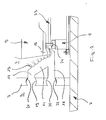
- a dryer is schematically and collectively designated by the reference numeral 1, which serves as an example of a tempering. It comprises in a known manner a housing 2 whose interior is divided by two longitudinally extending walls 3, 4 in two lateral pressure chambers 5, 6 and a lying in the middle as a drying tunnel tempering 7.
- a conveyor system 8 extends through the drying tunnel 7 and conveys the freshly coated vehicle bodies 9 to be dried, perpendicular to the drawing plane, through the drying tunnel 7.
- At the inlet and at the outlet of the drying tunnel 7 are located in a known manner an inlet or an outlet lock, which are not shown and need not be described in detail.
- nozzles 10, 11 are provided, which connect the pressure chambers 5, 6 with the drying tunnel 7.
- These nozzles 10, 11 have conventional construction and need not be described in detail. They are called “normal” nozzles here. It is sufficient to know that the orientation of its axis within the walls 3, 4 is adjustable as needed.
- nozzle devices 12, 13 are arranged, which also connect the pressure chambers 6 with the drying tunnel 7 and whose construction is now explained in more detail with reference to the nozzle device 12.
- the nozzle device 13 basically has the same structure.
- the nozzle device 12 has a middle, obliquely against both the vertical and the horizontal hired nozzle body 14, in which the vehicle body 9 side facing a plurality of individual nozzle openings 15 is provided.
- This side of the nozzle body 14 is adapted at least approximately to the sill area 16 of the vehicle body 9 and engages around this sill area 16 below, where even an undercut can be seen.
- the two opposite ends of the nozzle body 14 are approximately in the installed position horizontally extending connection channels 17, 18 connected to openings 19, 20 in the wall 3, which serve in conventional dryers receiving normal nozzles 10 and have for this purpose kugelkalottenförmige side surfaces.
- the ends of the connection channels 17, 18 are each provided with spherical cap-shaped clamping plates 21, 22. In this way, the entire nozzle device 12 can be clamped by inserting the clamping plates 21, 22 in the openings 19, 20 on the wall 3.
- the vehicle bodies 9 are located on their transport through the drying tunnel 7 by means of the conveyor system 8 on skids 23, as is well known in itself and have two running parallel to the direction of skids 24, 25. At these runners 24, 25, the transport system 8 is used for locomotion of the vehicle body connected to the skid 22. They are protected by a shielding plate 40 against the direct application of hot air.
- the two pressure chambers 5, 6 are connected in known manner with a source of hot pressurized air; generally located in the lower part of the drying tunnel 7 are not shown suction, through which the air can be removed from the drying tunnel 7 again.
- the dryer 1 is operated in recirculation mode; This means that the air extracted from the drying tunnel 7, cleaned and then reheated, is recirculated to the pressure chambers 5, 6 by means of a ventilator.
- the vehicle bodies 9 are subjected to either continuous movement or at standstill via the normal nozzles 10, 11 in the lateral and upper regions with hot air. This will be dried the relatively less mass-containing lateral and upper portions of the vehicle body 9.
- the hot air coming from the pressure chambers 5, 6 is relatively close to the surface of the vehicle body 9 by means of the nozzle devices 12, 13. in particular of the sill area 12, introduced, which is applied in this way there particularly intense hot air.
- a favorable distance is about 20 cm, for the body floor acting nozzle openings 15 also only 10 cm. Due to the proximity between the nozzle openings 15 of the nozzle devices 12, 13 and the corresponding surface regions of the vehicle bodies 9, it is also possible to sufficiently heat the massive subregion of the vehicle body 9 in a time for drying which corresponds approximately to the time within which the normal nozzles 10 , 11 are capable of drying the upper portion of the vehicle body 9. In this way, the cycle times during drying of the vehicle body 9 can be reduced and overheating, which could not be excluded in the conventional dryer in the upper region of the vehicle body 9, avoided.
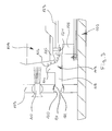
- FIG. 3 is in a sectional view, which is the FIG. 2 corresponds, a variant of a dryer 101 shown in fragmentary form.
- Corresponding parts in FIG. 3 are denoted by the same reference numerals as in FIG. 2 , but increased by 100, marked.
- Recognition in FIG. 3 are the longitudinal wall 103, which separates the pressure chamber 105 from the drying tunnel 107, and a normal nozzle 110.
- This nozzle 110 is located in an opening 119 of the wall 103, which in the embodiment of figure 2 the inclusion of a connection channel 17 of the nozzle device 12 has served.
- FIG. 3 is in a sectional view, which is the FIG. 2 corresponds, a variant of a dryer 101 shown in fragmentary form.
- Corresponding parts in FIG. 3 are denoted by the same reference numerals as in FIG. 2 , but increased by 100, marked.
- Recognition in FIG. 3 are the longitudinal wall 103, which separates the pressure chamber 105 from the drying tunnel 107, and a normal
- the nozzle device 112 has only one connection channel 118, at the ends of which two clamping plates 121, 122 are found, which are clamped in the opening 120 of the wall 103. Also, the nozzle body 114 of the nozzle device 112 has in the vehicle body 109 side facing a plurality of nozzle openings 115; this page is adapted in its contour of the contour of the sill area 116 of the body 109 to be dried.
- the embodiment of the nozzle device 112, which in FIG. 3 is slightly cheaper than that of the FIG. 2 and is mainly used where the need for hot air to dry the sill area 116 of the vehicle body 109 is not so great.
Landscapes
- Engineering & Computer Science (AREA)
- Mechanical Engineering (AREA)
- General Engineering & Computer Science (AREA)
- Drying Of Solid Materials (AREA)
- Coating Apparatus (AREA)
- Nozzles (AREA)
Claims (6)
- Dispositif de régulation de température de carrosseries de véhicules (9, 109), comprenanta) une enveloppe (2, 102) ;b) un tunnel de régulation de température (7, 107) logé dans l'enveloppe (2, 102), destiné à recevoir les carrosseries de véhicules (9, 109) ;c) au moins une chambre de pression (5, 6 ; 105) logée dans l'enveloppe (2, 102), séparée par une paroi (3, 4 ; 103) du tunnel de régulation de température (7, 107) ;d) une pluralité de buses (10, 11 ; 110) dans la paroi (3, 4 ; 103) ;e) un dispositif de régulation de température d'air qui introduit de l'air à température régulée dans la chambre de pression (5, 6 ; 105) de sorte que celui-ci puisse s'écouler par les buses (10, 11 ; 110) dans le tunnel de régulation de température (7, 107) et agir sur la carrosserie de véhicule (9, 109) s'y trouvant ;f) au moins un dispositif de buse (12, 13 ; 112) étant prévu, qui présente un corps de buse (14 ; 114) dont le côté tourné vers la carrosserie de véhicule (9 ; 109) est pourvu d'une pluralité d'ouvertures de buse (15; 115) et suit au moins approximativement la géométrie de la partie inférieure de la carrosserie de véhicule (9 ; 109) à une distance qui est inférieure à la distance entre les autres buses (10, 11 ; 110) disposées dans la même paroi (3, 4 ; 103) et la carrosserie de véhicule (9 ; 109) ;
caractérisé en ce queg) le dispositif de buse (12 ; 112) est fixé de manière détachable à au moins une ouverture (19, 20 ; 120) dans la paroi (3 ; 103) entre la chambre de pression (5 ; 105) et le tunnel de régulation de température (7 ; 107) ;h) ladite au moins une ouverture (19, 20 ; 120) à laquelle le dispositif de buse (12 ; 112) est fixé est configurée de la même manière que les ouvertures dans lesquelles les autres buses (10 ; 110) sont fixées dans la même paroi (3 ; 103). - Dispositif selon la revendication 1, caractérisé en ce que le dispositif de buse (12, 13 ; 112) entoure la carrosserie de véhicule (9 ; 109) en partie basse.
- Dispositif selon la revendication 1 ou 2, caractérisé en ce que la distance entre le côté du dispositif de buse (12, 13 ; 112) tourné vers la carrosserie de véhicule (9 ; 109) et la carrosserie de véhicule (9 ; 109) est d'environ 20 cm.
- Dispositif selon l'une des revendications précédentes, caractérisé en ce que le corps de buse est remplaçable.
- Dispositif selon l'une des revendications précédentes, caractérisé en ce que les ouvertures de buse (15 ; 115) suivent approximativement la géométrie du bas de caisse (16 ; 116).
- Dispositif selon l'une des revendications précédentes, caractérisé en ce qu'il est conçu pour sécher des carrosseries de véhicules (9 ; 109) revêtues.
Applications Claiming Priority (2)
| Application Number | Priority Date | Filing Date | Title |
|---|---|---|---|
| DE102011011261A DE102011011261A1 (de) | 2011-02-15 | 2011-02-15 | Vorrichtung zum Temperieren von Fahrzeugkarosserien |
| PCT/EP2012/000032 WO2012110172A1 (fr) | 2011-02-15 | 2012-01-05 | Dispositif pour réguler la température de carrosseries de véhicule |
Publications (2)
| Publication Number | Publication Date |
|---|---|
| EP2676092A1 EP2676092A1 (fr) | 2013-12-25 |
| EP2676092B1 true EP2676092B1 (fr) | 2015-05-20 |
Family
ID=45464581
Family Applications (1)
| Application Number | Title | Priority Date | Filing Date |
|---|---|---|---|
| EP20120700087 Active EP2676092B1 (fr) | 2011-02-15 | 2012-01-05 | Dispositif pour réguler la température de carrosseries de véhicule |
Country Status (9)
| Country | Link |
|---|---|
| US (1) | US10060676B2 (fr) |
| EP (1) | EP2676092B1 (fr) |
| CN (1) | CN103380343B (fr) |
| BR (1) | BR112013020785A8 (fr) |
| DE (1) | DE102011011261A1 (fr) |
| ES (1) | ES2542436T3 (fr) |
| MX (1) | MX2013004998A (fr) |
| RU (1) | RU2592689C2 (fr) |
| WO (1) | WO2012110172A1 (fr) |
Families Citing this family (11)
| Publication number | Priority date | Publication date | Assignee | Title |
|---|---|---|---|---|
| DE102011117666B4 (de) * | 2011-11-03 | 2019-01-17 | Eisenmann Se | Vorrichtung und Verfahren zum Temperieren von Gegenständen |
| DE102012020357B4 (de) * | 2012-10-16 | 2014-08-14 | Eisenmann Ag | Vorrichtung zum Temperieren von Gegenständen |
| EP3222951B1 (fr) * | 2014-11-20 | 2019-03-13 | Nissan Motor Co., Ltd | Dispositif de séchage de revêtement supérieur et procédé de séchage de revêtement supérieur |
| MY186755A (en) * | 2015-01-26 | 2021-08-18 | Nissan Motor | Paint baking oven and paint baking method |
| DE102015214706A1 (de) | 2015-07-31 | 2017-02-02 | Dürr Systems Ag | Behandlungsanlage und Verfahren zum Behandeln von Werkstücken |
| DE102015214711A1 (de) | 2015-07-31 | 2017-02-02 | Dürr Systems Ag | Behandlungsanlage und Verfahren zum Behandeln von Werkstücken |
| DE102015224916A1 (de) | 2015-12-10 | 2017-06-14 | Dürr Systems Ag | Behandlungsanlage und Verfahren zum Behandeln von Werkstücken |
| DE102016113062A1 (de) | 2016-07-15 | 2018-01-18 | Eisenmann Se | Vorrichtung, Anlage und Verfahren zum Temperieren von Werkstücken |
| DE102016125060B4 (de) * | 2016-12-21 | 2023-02-16 | Eisenmann Gmbh | Vorrichtung zum Temperieren von Gegenständen |
| DE102018113685A1 (de) * | 2018-06-08 | 2018-08-23 | Eisenmann Se | Anlage zum Trocknen von Fahrzeugkarosserien |
| DE102020207717A1 (de) | 2020-06-22 | 2021-12-23 | Dürr Systems Ag | Verfahren zum Temperieren von Fahrzeugkarosserien und Temperieranlage |
Family Cites Families (16)
| Publication number | Priority date | Publication date | Assignee | Title |
|---|---|---|---|---|
| GB615953A (en) * | 1945-09-20 | 1949-01-13 | Ford Motor Co | Improvements in apparatus for drying enamel and like coatings or materials |
| SE218360C1 (fr) * | 1962-02-19 | 1968-01-16 | ||
| FR2029314A5 (fr) * | 1969-01-24 | 1970-10-16 | Ventilation Indle Minier | |
| EP0268691A1 (fr) | 1986-11-20 | 1988-06-01 | Thomas Lammers | Dispositif pour sécher des pièces de construction pourvues d'une couche superficielle |
| CA1309755C (fr) | 1987-03-30 | 1992-11-03 | Hiroyoshi Nozaki | Methode de cuisson de couche de protection |
| US5018966A (en) * | 1989-03-20 | 1991-05-28 | Hunter Engineering Company, Inc. | Strip drying or curing oven |
| DE4024107C1 (fr) * | 1990-07-30 | 1992-04-16 | Eastman Christensen Co., Salt Lake City, Utah, Us | |
| JPH04358556A (ja) * | 1991-06-04 | 1992-12-11 | Honda Motor Co Ltd | 塗装乾燥炉 |
| US5456023A (en) * | 1994-06-28 | 1995-10-10 | Ransburg Corporation | Advance cure paint spray booth |
| CA2254467C (fr) * | 1997-11-21 | 2007-10-09 | Masanori Ino | Four de sechage de la peinture |
| DE10125771C1 (de) * | 2001-05-26 | 2002-11-21 | Eisenmann Kg Maschbau | Trockner |
| DE102004023539A1 (de) * | 2003-07-24 | 2005-03-03 | EISENMANN Maschinenbau KG (Komplementär: Eisenmann-Stiftung) | Vorrichtung zur Aushärtung einer aus einem Material, das unter elektromagnetischer Strahlung aushärtet, insbesondere aus einem UV-Lack oder aus einem thermisch aushärtenden Lack, bestehenden Beschichtung eines Gegenstandes |
| US7063528B2 (en) * | 2003-10-23 | 2006-06-20 | Durr Systems Inc. | Radiant tube and convection oven |
| DE102004001628B4 (de) * | 2004-01-12 | 2006-08-10 | Eisenmann Maschinenbau Gmbh & Co. Kg | Vorrichtung zur Behandlung von Gegenständen mit mindestens einem temperierten, gerichteten Luftstrahl |
| US9513057B2 (en) * | 2006-06-16 | 2016-12-06 | Durr Systems, Inc. | Radiant convection oven |
| US8393895B2 (en) | 2008-08-17 | 2013-03-12 | GM Global Technology Operations LLC | Transverse oven and method of baking workpieces |
-
2011
- 2011-02-15 DE DE102011011261A patent/DE102011011261A1/de not_active Withdrawn
-
2012
- 2012-01-05 BR BR112013020785A patent/BR112013020785A8/pt active Search and Examination
- 2012-01-05 MX MX2013004998A patent/MX2013004998A/es unknown
- 2012-01-05 ES ES12700087.5T patent/ES2542436T3/es active Active
- 2012-01-05 WO PCT/EP2012/000032 patent/WO2012110172A1/fr not_active Ceased
- 2012-01-05 CN CN201280008785.6A patent/CN103380343B/zh active Active
- 2012-01-05 US US13/984,583 patent/US10060676B2/en active Active
- 2012-01-05 EP EP20120700087 patent/EP2676092B1/fr active Active
- 2012-01-05 RU RU2013136133/06A patent/RU2592689C2/ru not_active IP Right Cessation
Also Published As
| Publication number | Publication date |
|---|---|
| MX2013004998A (es) | 2013-08-01 |
| EP2676092A1 (fr) | 2013-12-25 |
| US20130312277A1 (en) | 2013-11-28 |
| BR112013020785A8 (pt) | 2017-10-10 |
| ES2542436T3 (es) | 2015-08-05 |
| BR112013020785A2 (pt) | 2016-10-11 |
| CN103380343A (zh) | 2013-10-30 |
| CN103380343B (zh) | 2015-09-23 |
| WO2012110172A1 (fr) | 2012-08-23 |
| RU2013136133A (ru) | 2015-02-10 |
| US10060676B2 (en) | 2018-08-28 |
| DE102011011261A1 (de) | 2012-08-16 |
| RU2592689C2 (ru) | 2016-07-27 |
Similar Documents
| Publication | Publication Date | Title |
|---|---|---|
| WO2012110172A1 (fr) | Dispositif pour réguler la température de carrosseries de véhicule | |
| DE102011011898B4 (de) | Vorrichtung zum Temperieren von Fahrzeugkarosserien | |
| EP3075902B1 (fr) | Dispositif de nettoyage | |
| EP3361926B1 (fr) | Lave-vaisselle muni d'un dispositif de préséchage, procédé pour présécher de la vaisselle | |
| EP2775240B1 (fr) | Dispositif de traitement d'un revêtement d'une carrosserie de véhicule | |
| EP3717850B1 (fr) | Arrangement et procédé de thermostatisation de pièces | |
| EP1450867B2 (fr) | Tunnel sterilisateur pour recipients pharmaceutiques | |
| DE19649073C2 (de) | Vorrichtung zur Abkühlung von Strangpreßprofilen | |
| EP2946158B1 (fr) | Dispositif de régulation de la température d'objets | |
| EP2773914B1 (fr) | Dispositif et procédé permettant de thermoréguler des objets | |
| DE102012020357B4 (de) | Vorrichtung zum Temperieren von Gegenständen | |
| WO2018011389A1 (fr) | Dispositif, système et procédé servant à réguler la température de pièces | |
| EP2439474B1 (fr) | Dispositif de séchage d'un élément de machine doté d'une chambre sèche sous vide | |
| EP2744601B1 (fr) | Procédé et installation de traitement d'objets | |
| EP2706866B1 (fr) | Dispositif de dragéification | |
| DE102017118867B4 (de) | Verladekopf eines pneumatischen Verladesystems für Schüttgüter | |
| DE102017110926A1 (de) | Vorrichtung und Verfahren zum Temperieren von Werkstücken, insbesondere von Fahrzeugkarosserien | |
| EP2505950A1 (fr) | Support de pièce usinée et installation destinée au traitement d'objets | |
| EP0400459A1 (fr) | Installation pour arroser des marchandises dans un local de chargement | |
| DE10017687A1 (de) | Vorrichtung zur Zuführung von Heißluft | |
| DE4111125C1 (en) | Method and appts. for accelerated cooling of long hollow components | |
| DE1092453B (de) | Vorrichtung zur Behandlung von foerderbandartig fortbewegtem Material mit einem gasfoermigen Medium | |
| CH691927A5 (de) | Vorrichtung zum gepulsten Ausgeben eines Mediums zur Behandlung von Oberflächen. |
Legal Events
| Date | Code | Title | Description |
|---|---|---|---|
| PUAI | Public reference made under article 153(3) epc to a published international application that has entered the european phase |
Free format text: ORIGINAL CODE: 0009012 |
|
| 17P | Request for examination filed |
Effective date: 20130723 |
|
| AK | Designated contracting states |
Kind code of ref document: A1 Designated state(s): AL AT BE BG CH CY CZ DE DK EE ES FI FR GB GR HR HU IE IS IT LI LT LU LV MC MK MT NL NO PL PT RO RS SE SI SK SM TR |
|
| DAX | Request for extension of the european patent (deleted) | ||
| GRAP | Despatch of communication of intention to grant a patent |
Free format text: ORIGINAL CODE: EPIDOSNIGR1 |
|
| INTG | Intention to grant announced |
Effective date: 20141128 |
|
| GRAS | Grant fee paid |
Free format text: ORIGINAL CODE: EPIDOSNIGR3 |
|
| GRAA | (expected) grant |
Free format text: ORIGINAL CODE: 0009210 |
|
| AK | Designated contracting states |
Kind code of ref document: B1 Designated state(s): AL AT BE BG CH CY CZ DE DK EE ES FI FR GB GR HR HU IE IS IT LI LT LU LV MC MK MT NL NO PL PT RO RS SE SI SK SM TR |
|
| REG | Reference to a national code |
Ref country code: GB Ref legal event code: FG4D Free format text: NOT ENGLISH |
|
| REG | Reference to a national code |
Ref country code: CH Ref legal event code: EP |
|
| REG | Reference to a national code |
Ref country code: AT Ref legal event code: REF Ref document number: 727939 Country of ref document: AT Kind code of ref document: T Effective date: 20150615 |
|
| REG | Reference to a national code |
Ref country code: IE Ref legal event code: FG4D Free format text: LANGUAGE OF EP DOCUMENT: GERMAN |
|
| REG | Reference to a national code |
Ref country code: DE Ref legal event code: R096 Ref document number: 502012003203 Country of ref document: DE Effective date: 20150702 |
|
| REG | Reference to a national code |
Ref country code: ES Ref legal event code: FG2A Ref document number: 2542436 Country of ref document: ES Kind code of ref document: T3 Effective date: 20150805 |
|
| REG | Reference to a national code |
Ref country code: LT Ref legal event code: MG4D |
|
| REG | Reference to a national code |
Ref country code: NL Ref legal event code: MP Effective date: 20150520 |
|
| PG25 | Lapsed in a contracting state [announced via postgrant information from national office to epo] |
Ref country code: LT Free format text: LAPSE BECAUSE OF FAILURE TO SUBMIT A TRANSLATION OF THE DESCRIPTION OR TO PAY THE FEE WITHIN THE PRESCRIBED TIME-LIMIT Effective date: 20150520 Ref country code: NO Free format text: LAPSE BECAUSE OF FAILURE TO SUBMIT A TRANSLATION OF THE DESCRIPTION OR TO PAY THE FEE WITHIN THE PRESCRIBED TIME-LIMIT Effective date: 20150820 Ref country code: PT Free format text: LAPSE BECAUSE OF FAILURE TO SUBMIT A TRANSLATION OF THE DESCRIPTION OR TO PAY THE FEE WITHIN THE PRESCRIBED TIME-LIMIT Effective date: 20150921 Ref country code: FI Free format text: LAPSE BECAUSE OF FAILURE TO SUBMIT A TRANSLATION OF THE DESCRIPTION OR TO PAY THE FEE WITHIN THE PRESCRIBED TIME-LIMIT Effective date: 20150520 Ref country code: HR Free format text: LAPSE BECAUSE OF FAILURE TO SUBMIT A TRANSLATION OF THE DESCRIPTION OR TO PAY THE FEE WITHIN THE PRESCRIBED TIME-LIMIT Effective date: 20150520 |
|
| PG25 | Lapsed in a contracting state [announced via postgrant information from national office to epo] |
Ref country code: LV Free format text: LAPSE BECAUSE OF FAILURE TO SUBMIT A TRANSLATION OF THE DESCRIPTION OR TO PAY THE FEE WITHIN THE PRESCRIBED TIME-LIMIT Effective date: 20150520 Ref country code: IS Free format text: LAPSE BECAUSE OF FAILURE TO SUBMIT A TRANSLATION OF THE DESCRIPTION OR TO PAY THE FEE WITHIN THE PRESCRIBED TIME-LIMIT Effective date: 20150920 Ref country code: GR Free format text: LAPSE BECAUSE OF FAILURE TO SUBMIT A TRANSLATION OF THE DESCRIPTION OR TO PAY THE FEE WITHIN THE PRESCRIBED TIME-LIMIT Effective date: 20150821 Ref country code: BG Free format text: LAPSE BECAUSE OF FAILURE TO SUBMIT A TRANSLATION OF THE DESCRIPTION OR TO PAY THE FEE WITHIN THE PRESCRIBED TIME-LIMIT Effective date: 20150820 Ref country code: RS Free format text: LAPSE BECAUSE OF FAILURE TO SUBMIT A TRANSLATION OF THE DESCRIPTION OR TO PAY THE FEE WITHIN THE PRESCRIBED TIME-LIMIT Effective date: 20150520 |
|
| REG | Reference to a national code |
Ref country code: FR Ref legal event code: PLFP Year of fee payment: 5 |
|
| PG25 | Lapsed in a contracting state [announced via postgrant information from national office to epo] |
Ref country code: DK Free format text: LAPSE BECAUSE OF FAILURE TO SUBMIT A TRANSLATION OF THE DESCRIPTION OR TO PAY THE FEE WITHIN THE PRESCRIBED TIME-LIMIT Effective date: 20150520 Ref country code: EE Free format text: LAPSE BECAUSE OF FAILURE TO SUBMIT A TRANSLATION OF THE DESCRIPTION OR TO PAY THE FEE WITHIN THE PRESCRIBED TIME-LIMIT Effective date: 20150520 |
|
| REG | Reference to a national code |
Ref country code: DE Ref legal event code: R097 Ref document number: 502012003203 Country of ref document: DE |
|
| PG25 | Lapsed in a contracting state [announced via postgrant information from national office to epo] |
Ref country code: RO Free format text: LAPSE BECAUSE OF NON-PAYMENT OF DUE FEES Effective date: 20150520 Ref country code: PL Free format text: LAPSE BECAUSE OF FAILURE TO SUBMIT A TRANSLATION OF THE DESCRIPTION OR TO PAY THE FEE WITHIN THE PRESCRIBED TIME-LIMIT Effective date: 20150520 Ref country code: CZ Free format text: LAPSE BECAUSE OF FAILURE TO SUBMIT A TRANSLATION OF THE DESCRIPTION OR TO PAY THE FEE WITHIN THE PRESCRIBED TIME-LIMIT Effective date: 20150520 Ref country code: SK Free format text: LAPSE BECAUSE OF FAILURE TO SUBMIT A TRANSLATION OF THE DESCRIPTION OR TO PAY THE FEE WITHIN THE PRESCRIBED TIME-LIMIT Effective date: 20150520 |
|
| REG | Reference to a national code |
Ref country code: DE Ref legal event code: R081 Ref document number: 502012003203 Country of ref document: DE Owner name: EISENMANN GMBH, DE Free format text: FORMER OWNER: EISENMANN AG, 71032 BOEBLINGEN, DE Ref country code: DE Ref legal event code: R082 Ref document number: 502012003203 Country of ref document: DE Representative=s name: OSTERTAG & PARTNER, PATENTANWAELTE MBB, DE Ref country code: DE Ref legal event code: R081 Ref document number: 502012003203 Country of ref document: DE Owner name: EISENMANN SE, DE Free format text: FORMER OWNER: EISENMANN AG, 71032 BOEBLINGEN, DE |
|
| PLBE | No opposition filed within time limit |
Free format text: ORIGINAL CODE: 0009261 |
|
| STAA | Information on the status of an ep patent application or granted ep patent |
Free format text: STATUS: NO OPPOSITION FILED WITHIN TIME LIMIT |
|
| 26N | No opposition filed |
Effective date: 20160223 |
|
| PG25 | Lapsed in a contracting state [announced via postgrant information from national office to epo] |
Ref country code: SI Free format text: LAPSE BECAUSE OF FAILURE TO SUBMIT A TRANSLATION OF THE DESCRIPTION OR TO PAY THE FEE WITHIN THE PRESCRIBED TIME-LIMIT Effective date: 20150520 Ref country code: BE Free format text: LAPSE BECAUSE OF NON-PAYMENT OF DUE FEES Effective date: 20160131 |
|
| PG25 | Lapsed in a contracting state [announced via postgrant information from national office to epo] |
Ref country code: LU Free format text: LAPSE BECAUSE OF FAILURE TO SUBMIT A TRANSLATION OF THE DESCRIPTION OR TO PAY THE FEE WITHIN THE PRESCRIBED TIME-LIMIT Effective date: 20160105 |
|
| REG | Reference to a national code |
Ref country code: CH Ref legal event code: PL |
|
| GBPC | Gb: european patent ceased through non-payment of renewal fee |
Effective date: 20160105 |
|
| PG25 | Lapsed in a contracting state [announced via postgrant information from national office to epo] |
Ref country code: MC Free format text: LAPSE BECAUSE OF FAILURE TO SUBMIT A TRANSLATION OF THE DESCRIPTION OR TO PAY THE FEE WITHIN THE PRESCRIBED TIME-LIMIT Effective date: 20150520 |
|
| PG25 | Lapsed in a contracting state [announced via postgrant information from national office to epo] |
Ref country code: GB Free format text: LAPSE BECAUSE OF NON-PAYMENT OF DUE FEES Effective date: 20160105 Ref country code: CH Free format text: LAPSE BECAUSE OF NON-PAYMENT OF DUE FEES Effective date: 20160131 Ref country code: LI Free format text: LAPSE BECAUSE OF NON-PAYMENT OF DUE FEES Effective date: 20160131 |
|
| REG | Reference to a national code |
Ref country code: IE Ref legal event code: MM4A |
|
| REG | Reference to a national code |
Ref country code: FR Ref legal event code: PLFP Year of fee payment: 6 |
|
| PG25 | Lapsed in a contracting state [announced via postgrant information from national office to epo] |
Ref country code: IE Free format text: LAPSE BECAUSE OF NON-PAYMENT OF DUE FEES Effective date: 20160105 |
|
| PG25 | Lapsed in a contracting state [announced via postgrant information from national office to epo] |
Ref country code: NL Free format text: LAPSE BECAUSE OF FAILURE TO SUBMIT A TRANSLATION OF THE DESCRIPTION OR TO PAY THE FEE WITHIN THE PRESCRIBED TIME-LIMIT Effective date: 20150520 Ref country code: SE Free format text: LAPSE BECAUSE OF FAILURE TO SUBMIT A TRANSLATION OF THE DESCRIPTION OR TO PAY THE FEE WITHIN THE PRESCRIBED TIME-LIMIT Effective date: 20150520 |
|
| PG25 | Lapsed in a contracting state [announced via postgrant information from national office to epo] |
Ref country code: MT Free format text: LAPSE BECAUSE OF FAILURE TO SUBMIT A TRANSLATION OF THE DESCRIPTION OR TO PAY THE FEE WITHIN THE PRESCRIBED TIME-LIMIT Effective date: 20150520 |
|
| REG | Reference to a national code |
Ref country code: FR Ref legal event code: PLFP Year of fee payment: 7 |
|
| REG | Reference to a national code |
Ref country code: AT Ref legal event code: MM01 Ref document number: 727939 Country of ref document: AT Kind code of ref document: T Effective date: 20170105 |
|
| PG25 | Lapsed in a contracting state [announced via postgrant information from national office to epo] |
Ref country code: HU Free format text: LAPSE BECAUSE OF FAILURE TO SUBMIT A TRANSLATION OF THE DESCRIPTION OR TO PAY THE FEE WITHIN THE PRESCRIBED TIME-LIMIT; INVALID AB INITIO Effective date: 20120105 Ref country code: AT Free format text: LAPSE BECAUSE OF NON-PAYMENT OF DUE FEES Effective date: 20170105 Ref country code: SM Free format text: LAPSE BECAUSE OF FAILURE TO SUBMIT A TRANSLATION OF THE DESCRIPTION OR TO PAY THE FEE WITHIN THE PRESCRIBED TIME-LIMIT Effective date: 20150520 Ref country code: CY Free format text: LAPSE BECAUSE OF FAILURE TO SUBMIT A TRANSLATION OF THE DESCRIPTION OR TO PAY THE FEE WITHIN THE PRESCRIBED TIME-LIMIT Effective date: 20150520 |
|
| PG25 | Lapsed in a contracting state [announced via postgrant information from national office to epo] |
Ref country code: TR Free format text: LAPSE BECAUSE OF FAILURE TO SUBMIT A TRANSLATION OF THE DESCRIPTION OR TO PAY THE FEE WITHIN THE PRESCRIBED TIME-LIMIT Effective date: 20150520 Ref country code: MK Free format text: LAPSE BECAUSE OF FAILURE TO SUBMIT A TRANSLATION OF THE DESCRIPTION OR TO PAY THE FEE WITHIN THE PRESCRIBED TIME-LIMIT Effective date: 20150520 |
|
| PG25 | Lapsed in a contracting state [announced via postgrant information from national office to epo] |
Ref country code: AL Free format text: LAPSE BECAUSE OF FAILURE TO SUBMIT A TRANSLATION OF THE DESCRIPTION OR TO PAY THE FEE WITHIN THE PRESCRIBED TIME-LIMIT Effective date: 20150520 |
|
| REG | Reference to a national code |
Ref country code: FR Ref legal event code: PLFP Year of fee payment: 9 |
|
| PGFP | Annual fee paid to national office [announced via postgrant information from national office to epo] |
Ref country code: ES Payment date: 20200221 Year of fee payment: 9 |
|
| PGFP | Annual fee paid to national office [announced via postgrant information from national office to epo] |
Ref country code: FR Payment date: 20200121 Year of fee payment: 9 |
|
| REG | Reference to a national code |
Ref country code: DE Ref legal event code: R081 Ref document number: 502012003203 Country of ref document: DE Owner name: EISENMANN GMBH, DE Free format text: FORMER OWNER: EISENMANN SE, 71032 BOEBLINGEN, DE |
|
| PG25 | Lapsed in a contracting state [announced via postgrant information from national office to epo] |
Ref country code: FR Free format text: LAPSE BECAUSE OF NON-PAYMENT OF DUE FEES Effective date: 20210131 |
|
| REG | Reference to a national code |
Ref country code: ES Ref legal event code: FD2A Effective date: 20220422 |
|
| PG25 | Lapsed in a contracting state [announced via postgrant information from national office to epo] |
Ref country code: ES Free format text: LAPSE BECAUSE OF NON-PAYMENT OF DUE FEES Effective date: 20210106 |
|
| PGFP | Annual fee paid to national office [announced via postgrant information from national office to epo] |
Ref country code: DE Payment date: 20260121 Year of fee payment: 15 |
|
| PGFP | Annual fee paid to national office [announced via postgrant information from national office to epo] |
Ref country code: IT Payment date: 20260130 Year of fee payment: 15 |