EP2676330B1 - Blindsteckbare verbindung und kontakt - Google Patents
Blindsteckbare verbindung und kontakt Download PDFInfo
- Publication number
- EP2676330B1 EP2676330B1 EP12746846.0A EP12746846A EP2676330B1 EP 2676330 B1 EP2676330 B1 EP 2676330B1 EP 12746846 A EP12746846 A EP 12746846A EP 2676330 B1 EP2676330 B1 EP 2676330B1
- Authority
- EP
- European Patent Office
- Prior art keywords
- contact
- insulator
- mating
- socket contact
- cantilevered arm
- Prior art date
- Legal status (The legal status is an assumption and is not a legal conclusion. Google has not performed a legal analysis and makes no representation as to the accuracy of the status listed.)
- Active
Links
Images







Classifications
-
- H—ELECTRICITY
- H01—ELECTRIC ELEMENTS
- H01R—ELECTRICALLY-CONDUCTIVE CONNECTIONS; STRUCTURAL ASSOCIATIONS OF A PLURALITY OF MUTUALLY-INSULATED ELECTRICAL CONNECTING ELEMENTS; COUPLING DEVICES; CURRENT COLLECTORS
- H01R13/00—Details of coupling devices of the kinds covered by groups H01R12/70 or H01R24/00 - H01R33/00
- H01R13/02—Contact members
- H01R13/10—Sockets for co-operation with pins or blades
- H01R13/11—Resilient sockets
- H01R13/111—Resilient sockets co-operating with pins having a circular transverse section
-
- H—ELECTRICITY
- H01—ELECTRIC ELEMENTS
- H01R—ELECTRICALLY-CONDUCTIVE CONNECTIONS; STRUCTURAL ASSOCIATIONS OF A PLURALITY OF MUTUALLY-INSULATED ELECTRICAL CONNECTING ELEMENTS; COUPLING DEVICES; CURRENT COLLECTORS
- H01R13/00—Details of coupling devices of the kinds covered by groups H01R12/70 or H01R24/00 - H01R33/00
- H01R13/62—Means for facilitating engagement or disengagement of coupling parts or for holding them in engagement
- H01R13/629—Additional means for facilitating engagement or disengagement of coupling parts, e.g. aligning or guiding means, levers, gas pressure electrical locking indicators, manufacturing tolerances
- H01R13/631—Additional means for facilitating engagement or disengagement of coupling parts, e.g. aligning or guiding means, levers, gas pressure electrical locking indicators, manufacturing tolerances for engagement only
- H01R13/6315—Additional means for facilitating engagement or disengagement of coupling parts, e.g. aligning or guiding means, levers, gas pressure electrical locking indicators, manufacturing tolerances for engagement only allowing relative movement between coupling parts, e.g. floating connection
Definitions
- the disclosure relates generally to electrical connectors, and particularly to coaxial connectors, and more particularly to blind mate interconnects utilizing coaxial socket contacts having cantilevered arms that wrap around a central axis for improving mating cycle performance.
- coaxial connectors including microwave frequency connectors
- connectors designed to transmit electrical signals and/or power Male and female interfaces may be engaged and disengaged to connect and disconnect the electrical signals and/or power.
- These interfaces typically utilize socket contacts that are designed to engage pin contacts. These metallic contacts are generally surrounded by a plastic insulator with dielectric characteristics. A metallic housing surrounds the insulator to provide electrical grounding and isolation from electrical interference or noise. These connector assemblies may be coupled by various methods including a push-on design.
- the dielectric properties of the plastic insulator along with its position between the contact and the housing produce an electrical impedance, such as 50 ohms.
- Microwave or radio frequency (RF) systems with a matched electrical impedance are more power efficient and therefore capable of improved electrical performance.
- DC connectors utilize a similar contact, insulator, and housing configuration. DC connectors do not required impedance matching. Mixed signal applications including DC and RF are common.
- Connector assemblies may be coupled by various methods including a push-on design.
- the connector configuration may be a two piece system (male to female) or a three piece system (male to female-female to male).
- the three piece connector system utilizes a double ended female interface known as a blind-mate interconnect (BMI).
- BMI blind-mate interconnect
- the BMI includes a double ended socket contact, two or more insulators, and a metallic housing with grounding fingers.
- the three piece connector system also utilizes two male interfaces each with a pin contact, insulator, and metallic housing called a shroud.
- the insulator of the male interface is typically plastic or glass.
- the shroud may have a detent feature that engages the front fingers of the BMI metallic housing for mated retention. This detent feature may be modified thus resulting in high and low retention forces for various applications.
- the three piece connector system enables improved electrical and mechanical performance during radial and axial misalignment.
- Socket contacts are a key component in the transmission of the electrical signal.
- Conventional socket contacts used in coaxial connectors typically utilize a straight or tapered beam design that requires time consuming traditional machining and forming techniques. Such contacts, upon engagement, typically result in a non-circular cross section, such as an oval, triangular, square or other simple geometric cross section, depending on the number of beams. These non-circular cross sections may result in degraded electrical performance.
- conventional beam sockets when exposed to forces that cause mated misalignment of pin contacts, conventional beam sockets tend to flare and may, therefore, degrade the contact points. In such instances, conventional beam sockets may also lose contact with the contact pins or become distorted, causing damage to the beams or a degradation in RF performance. What is needed is a coaxial socket contact with reliable mating characteristics that can withstand repeated mating cycles without degradation of mechanical and electrical performance.
- US 2008/194124 A1 discloses a coaxial socket contact. Further US 2008/194124 A1 discloses a blind mate interconnect showing the features of the preamble of claim 1.
- the invention provides a blind mate interconnect according to claim 1.
- the blind mate interconnect comprising a coaxial socket contact for connecting to a coaxial transmission medium to form an electrically conductive path between the transmission medium and the coaxial socket contact.
- a socket contact 100 may include a main body 102 extending along a longitudinal axis ( FIG. 1 ).
- Main body 102 may have a proximal portion 104, a distal portion 108, and a central portion 106 that may be axially between proximal portion 104 and distal portion 108.
- proximal portion 104, distal portion 108, and central portion 106 may have inner and outer surfaces.
- Main body 102 may also have a first end 110 disposed on proximal portion 104 and an opposing second end 112 disposed on distal portion 108.
- Main body 102 may be comprised of electrically conductive and mechanically resilient material having spring-like characteristics, for example, that extends circumferentially around the longitudinal axis.
- Materials for main body 102 may include, but are not limited to, gold plated beryllium copper (BeCu), stainless steel, or a cobalt-chromium-nickel-molybdenum-iron alloy such as Conichrome, Phynox, and Elgiloy.
- An exemplary material for main body 102 may be gold plated beryllium copper (BeCu).
- socket contact 100 may include a plurality of external openings 114 associated with proximal portion 104.
- at least one of external openings 114 extends for a distance from, for example, first end 110, along at least a part of the longitudinal length of proximal portion 104 between the inner and outer surfaces of proximal portion 104.
- Socket contact 100 may include at least one internal opening 116, for example, that may be substantially parallel to openings 114, but does not extend to first end 110.
- socket contact 100 may also include other external openings 120 associated with distal portion 108.
- At least one of external openings 120 extends for a distance from, for example, second end 112, along at least a part of the longitudinal length of distal portion 108 between the inner and outer surfaces of distal portion 108.
- Socket contact 100 may further include at least one other internal opening 122, for example, that may be substantially parallel to openings 120, but does not extend to second end 112.
- the openings extending along the longitudinal length of portions 104 and 108 delineate, for example, longitudinally oriented u-shaped slots.
- openings 114, 120 respectively extending from ends 110, 112 and openings 116, 122 respectively not extending to ends 110, 122 delineate longitudinally oriented u-shaped slots.
- socket contact 100 may include circumferentially oriented u-shaped slots delineated by a plurality of openings 118 extending at least partially circumferentially around central portion 106.
- the circumferentially oriented u-shaped slots may be generally perpendicular to longitudinally oriented u-shaped slots.
- the longitudinally oriented u-shaped slots delineated by openings 114, 116 and 120, 122 alternate in opposing directions such that, along the proximal portion 104 and distal portion 108.
- the electrically conductive and mechanically resilient material circumferentially extends around the longitudinal axis, for example, in a substantially axially parallel accordion-like pattern, along the proximal portion 104 and distal portion 108 ( FIG. 1 ).
- the radially outermost portion of electrically conductive and mechanically resilient material has a width, W, that in exemplary embodiments, may be approximately constant along different portions of the axially parallel accordion-like pattern.
- the radially outermost portion of electrically conductive and mechanically resilient material has a height, H.
- height H may be approximately constant along different portions of the pattern.
- the ratio of H/W may be from about 0.5 to about 2.0, such as from about 0.75 to about 1.5, including about 1.0.
- main body 102 may be of unitary construction.
- main body 102 may be constructed from, for example, a thin-walled cylindrical tube of electrically conductive and mechanically resilient material.
- patterns have been cut into the tube ( FIG. 1 ), such that the patterns define, for example, a plurality of openings that extend between the inner and outer surfaces of the tube.
- the thin wall tube may be fabricated to small sizes (for applications where, for example, small size and low weight are of importance) by various methods including, for example, extruding, drawing, and deep drawing, etc.
- the patterns may, for example, be laser machined, stamped, etched, electrical discharge machined or traditionally machined into the tube depending on the feature size. In exemplary embodiments, for example, the patterns are laser machined into the tube.
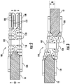
- socket contact 100 may engage a coaxial transmission medium, for example, a mating (male pin) contact 10 ( FIG. 2 ).
- An inner surface of proximal portion 104 and an inner surface of distal portion 108 may each be adapted to engage, for example, circumferentially, an outer surface of mating contact 10.
- proximal portion 104 and distal portion 108 Prior to engagement with mating contact 10, proximal portion 104 and distal portion 108 each have an inner width, or diameter, D1 that may be smaller than an outer diameter D2 of mating contact 10.
- engagement of the inner surface of proximal portion 104 or distal portion 108 with outer surface of mating contact 10 may cause portions 104 and 108 to flex radially outwardly.
- the inner diameter of proximal portion 104 and/or distal portion 108 may be at least equal to D2 ( FIG. 2 ).
- inner diameter of proximal portion 104 may be approximately equal to D2 upon engagement with mating contact 10 while distal portion 108 not being engaged to a mating contact may have an inner diameter of D1.
- Disengagement of the inner surface of proximal portion 104 and/or distal portion 108 with the outer surface of mating contact 10 may cause inner diameter of proximal portion 104 and/or distal portion 108 to return to D1 .
- D2/D1 may be, in exemplary embodiments, at least 1.05, such as at least 1.1, and further such as at least 1.2, and yet further such as at least 1.3.
- the outward radial flexing of proximal portion 104 and/or distal portion 108 during engagement with mating contact 10 may result in a radially inward biasing force of socket contact 100 on mating contact 10, facilitating transmission of an electrical signal between socket contact 100 and mating contact 10 and also reducing the possibility of unwanted disengagement between socket contact 100 and mating contact 10.
- proximal portion 104 and the inner surface of distal portion 108 are adapted to contact the outer surface of mating contact 10 upon engagement with mating contact 10.
- proximal portion 104 and distal portion 108 may each have a circular or approximately circular shaped cross-section of uniform or approximately uniform inner diameter of D1 along their longitudinal lengths prior to or subsequent to engagement with mating contact 10.
- proximal portion 104 and distal portion 108 may each have a circular or approximately circular shaped cross-section of uniform or approximately uniform inner diameter of at least D2 along a length of engagement with mating contact 10.
- the region bounded by inner surface of proximal portion 104 and the area bounded by inner surface of distal portion 108 each approximates that of a cylinder having a diameter of D1 prior to or subsequent to engagement with mating contact 10
- the region bounded by inner surface of proximal portion 104 and the area bounded by inner surface of distal portion 108 each approximates that of a cylinder having a diameter of D2 during engagement with mating contact 10.
- socket contact 100 may simultaneously engage two mating (male pin) contacts 10 and 12 ( FIG. 3 ).
- Mating contact 10 may, for example, circumferentially engage proximal portion 104 and mating contact 12 may circumferentially engage distal portion 108.
- mating contact 10 may not be coaxial with mating contact 12, resulting in an axial offset distance A (or mated misalignment) between the longitudinal axis of mating contact 10 and the longitudinal axis of mating contact 12 ( FIG. 3 ).
- socket contact 100 may be adapted to flex, for example, along central portion 106, compensating for mating misalignment between, for example, mating contact 10 and mating contact 12.
- types of mating misalignment may include, but are not limited to, radial misalignment, axial misalignment and angular misalignment.
- radial misalignment may be defined as the distance between the two mating pin (e.g., mating contact) axes and may be quantified by measuring the radial distance between the imaginary centerline of one pin if it were to be extended to overlap the other pin.
- axial misalignment may be defined as the variation in axial distance between the respective corresponding points of two mating pins.
- angular misalignment may be defined as the effective angle between the two imaginary pin centerlines and may usually be quantified by measuring the angle between the pin centerlines as if they were extended until they intersect.
- socket contact 100 may gimbal between, for example, mating contact 10 and mating contact 12 while still maintaining radially inward biasing force of socket contact 100 on mating contacts 10 and 12.
- the radially inward biasing force of socket contact 100 on mating contacts 10, 12 facilitates transmission of, for example, an electrical signal between socket contact 100 and mating contacts 10 and 12 and reduces the possibility of unwanted disengagement during mated misalignment.
- each of proximal portion 104 and distal portion 108 may have a circular or approximately circular shaped cross-section of a nominally uniform inner diameter of D1 along their respective longitudinal lengths prior to or subsequent to engagement with mating contacts 10 and 12. Additionally, each of proximal portion 104 and distal portion 108 may have a circular or approximately circular shaped cross-section of a nominally uniform inner diameter of at least D2 along their longitudinal lengths during engagement with mating contacts 10 and 12.
- the space bounded by inner surface of proximal portion 104 and the space bounded by inner surface of distal portion 108 each approximates that of a cylinder having a nominal diameter of D1 prior to or subsequent to engagement with mating contacts 10 and 12 and the space bounded by inner surface of proximal portion 104 and the space bounded by inner surface of distal portion 108 each , in exemplary embodiments, approximates that of a cylinder having a nominal diameter of D2 during engagement with mating contacts 10 and 12.
- socket contact 100 may gimbal to compensate for a ratio of axial offset distance A to nominal diameter D1 , A/D1 , to be at least about 0.4, such as at least about 0.6, and further such as at least about 1.2. In further exemplary embodiments, socket contact 100 may gimbal to compensate for a ratio of axial offset distance A to nominal diameter D2, A/D2 to be at least about 0.3, such as at least about 0.5, and further such as at least about 1.0.
- socket contact 100 may gimbal to compensate for the longitudinal axis of mating contact 10 to be substantially parallel to the longitudinal axis of mating contact 12 when mating contacts 10 and 12 are not coaxial, for example, such as when A/D2 may be at least about 0.3, such as at least about 0.5, and further such as at least about 1.0.
- socket contact 100 may gimbal to compensate for the longitudinal axis of mating contact 10 to be substantially oblique to the longitudinal axis of mating contact 12 when mating contacts 10 and 12 are not coaxial, for example, when the relative angle between the respective longitudinal axes is not 180 degrees.
- Alternate embodiments may include, for example, embodiments having openings cut into only a single end ( FIG. 4 ).
- So called single ended variations may have the proximal portion of the socket adapted to engage, for example, a pin contact and the distal portion of the socket may, for example, be soldered or brazed to, for example, a wire, or, for example, soldered, brazed, or welded to another such contact as, for example, another socket/pin configuration.
- the single ended socket contact variations FIG. 4
- the single ended socket contact variations may be adapted to flex radially and axially along at least a portion of their longitudinal length.
- the different patterns on the single ended socket contacts may also be found on double ended embodiments, similar to socket contact 100 (see FIGS. 1-3 ).
- a blind mate interconnect (BMI) 500 may include, for example, socket contact 100, an insulator 200, and an outer conductor 300.
- Outer conductor 300 may extend substantially circumferentially about a longitudinal axis and may define a first central bore.
- Insulator 200 may be disposed within the first central bore and may extend substantially about the longitudinal axis.
- Insulator 200 may include a first insulator component 202 and second insulator component 204 that may, for example, cooperate to define a second central bore.
- socket contact 100 may be disposed within the second central bore.
- Outer conductor 300 may have a proximal end 302 and a distal end 304, with, for example, a tubular body extending between proximal end 302 and distal end 304.
- a first radial array of slots 306 may extend substantially diagonally, or helically, along the tubular body of conductor 300 from proximal end 302 for a distance
- a second radial array of slots 308 may extend substantially diagonally, or helically, along the tubular body of conductor 300 from proximal end 304 for a distance.
- Slots 306, 308 may provide a gap having a minimum width of about .0254 mm (.001 inches).
- Outer contact being made from an electrically conductive material, may optionally be plated, for example, by electroplating or by electroless plating, with another electrically conductive material, e.g., nickel and/or gold.
- the plating may add material to the outer surface of outer conductor 300, and may close the gap to about .01905 mm (.00075 inches) nominal.
- helical slots may be cut at an angle of, for example, less than 90 degrees relative to the longitudinal axis (not parallel to the longitudinal axis), such as from about 30 degrees to about 60 degrees relative to the longitudinal axis, and such as from about 40 degrees to about 50 degrees relative to the longitudinal axis.
- Slots 306 and 308 may define, respectively, a first array of substantially helical cantilevered beams 310 and a second array of substantially helical cantilevered beams 312.
- Helical cantilevered beams 310, 312 include, for example, at least a free end and a fixed end.
- first array of substantially helical cantilevered beams 310 may extend substantially helically around at least a portion of proximal end 302 and a second array of substantially helical cantilevered beams 312 extend substantially helically around at least a portion of distal end 304.
- Each of helical cantilevered beams 310 may include, for example, at least one retention finger 314 and at least one flange stop 316 and each of plurality of second cantilevered beams 312 includes at least one retention finger 318 and at least one flange stop 320.
- Slots 306 and 308 each may define at least one flange receptacle 322 and 324, respectively.
- flange receptacle 322 may be defined as the space bounded by flange stop 316, two adjacent helical cantilevered beams 310, and the fixed end for at least one of helical cantilevered beams 310.
- flange receptacle 324 may be defined as the space bounded by flange stop 318, two adjacent helical cantilevered beams 314, and the fixed end for at least one of helical cantilevered beams 314.
- Helical cantilevered beams 310 and 312, in exemplary embodiments, may deflect radially inwardly or outwardly as they engage an inside surface or an outside surface of a conductive outer housing of a coaxial transmission medium (see, e.g., FIGS. 8 and 12 ), for example, providing a biasing force for facilitating proper grounding.
- Outer conductor 300 may include, for example, at least one radial array of sinuate cuts at least partially disposed around the tubular body. the cuts delineating at least one radial array of sinuate sections, the sinuate sections cooperating with the at least one array of substantially helical cantilevered beams to compensate for misalignment within a coaxial transmission medium, the conductor comprising an electrically conductive material
- First insulator component 202 may include outer surface 205, inner surface 207 and reduced diameter portion 210.
- Second insulator component 204 includes outer surface 206, inner surface 208 and reduced diameter portion 212.
- Reduced diameter portions 210 and 212 allow insulator 200 to retain socket contact 100.
- reduced diameter portions 210 and 212 provide a lead in feature for mating contacts 10 and 12 (see, e.g., FIG. 8 ) to facilitate engagement between socket contact 100 and mating contacts 10 and 12.
- First insulator component 202 additionally may include an increased diameter portion 220 and second insulator component 204 may also include an increased diameter portion 222 ( FIG. 8 ), increased diameter portions 220, 222 may respectively have at least one flange 230 and 232 that engages outer conductor 300, specifically, respective flange receptacles 322 and 324 (see FIG. 6 ).
- each of first and second insulator components 202 and 204 are retained in outer conductor portion 300 by first being slid longitudinally from the respective proximal 302 or distal end 304 of outer conductor portion 300 toward the center of outer conductor portion 300 ( FIG. 7 ).
- First array of substantially helical cantilevered beams 310 and second array of substantially helical cantilevered beams 312 may be flexed radially outward to receive respective arrays of flanges 230 and 232 within respective flange receptacles 322, 324.
- flanges 230, 232 reside freely within respective flange receptacles 322, 324, and may not react radially in the event cantilevered beams 310, 312 flex, but may prevent relative axial movement during connection of first and second insulator components 202 and 204 as a connector is pushed or pulled against interconnect 500.
- outer conductor portion 300 may be made, for example, of a mechanically resilient electrically conductive material having spring-like characteristics, for example, a mechanically resilient metal or metal alloy.
- An exemplary material for the outer conductor portion 300 may be beryllium copper (BeCu), which may optionally be plated over with another material, e.g., nickel and/or gold.
- Insulator 200 including first insulator component 202 and second insulator component 204, may be, in exemplary embodiments, made from a plastic or dielectric material.
- Exemplary materials for insulator 200 include Torlon® (polyamide-imide), Vespel® (polyimide), and Ultem (Polyetherimide). Insulator 200 may be, for example, machined or molded.
- the dielectric characteristics of the insulators 202 and 204 along with their position between socket contact 100 and outer conductor portion 300 produce, for example, an electrical impedance of about 50 ohms. Fine tuning of the electrical impedance may be accomplished by changes to the size and/or shape of the socket contact 100, insulator 200, and/or outer conductor portion 300.
- Connector 500 may engage with two coaxial transmission mediums, e.g., first and second male connectors 600 and 700, having asymmetrical interfaces ( FIG. 8 ).
- First male connector 600 may be a detented connector and may include a conductive outer housing (or shroud) 602 extending circumferentially about a longitudinal axis, an insulator circumferentially surrounded by the conductive outer housing 602, and a conductive mating contact (male pin) 610 at least partially circumferentially surrounded by the insulator.
- Second male connector 700 may be, for example, a non-detented or smooth bore connector and also includes a conductive outer housing (or shroud) 702 extending circumferentially about a longitudinal axis, an insulator circumferentially surrounding by the conductive outer housing 702, and a conductive mating contact (male pin) 710 at least partially circumferentially surrounded by insulator 705.
- Outer conductor 300 may compensate for mating misalignment by one or more of radially expanding, radially contracting, axially compressing, axially stretching, bending, flexing, or combinations thereof.
- Mating misalignment may be integral to a single connector, for example, male connectors 600 or 700 or between two connectors, for example, both connectors 600 and 700.
- the array of retention fingers 314 located on the free end of the first array of cantilevered beams 310 may snap into a detent 634 of outer shroud 602, securing interconnect 500 into connector 600.
- Male pin 610 engages and makes an electrical connection with socket contact 100 housed within insulator 202. Any misalignment that may be present between male pin 610 and outer shroud 602 may be compensated by interconnect 500.
- a second connector, for example, connector 700, that may be misaligned relative to first connector 600 is compensated for by interconnect 500 in the same manner (see FIG. 10 ).
- Connector 500 may engage with two coaxial transmission mediums, e.g., first and second male connectors 600 and 700, having asymmetrical interfaces ( FIG. 8 ).
- First male connector 600 may be a detented connector and may include a conductive outer housing (or shroud) 602 extending circumferentially about a longitudinal axis, an insulator 605 circumferentially surrounded by the conductive outer housing 602, and a conductive mating contact (male pin) 610 at least partially circumferentially surrounded by insulator 605.
- Second male connector 700 may be, for example, a non-detented or smooth bore connector and also includes a conductive outer housing (or shroud) 702 extending circumferentially about a longitudinal axis, an insulator 705 circumferentially surrounding by the conductive outer housing 702, and a conductive mating contact (male pin) 710 at least partially circumferentially surrounded by insulator 705.
- a conductive outer housing (or shroud) 702 extending circumferentially about a longitudinal axis
- an insulator 705 circumferentially surrounding by the conductive outer housing 702
- a conductive mating contact (male pin) 710 at least partially circumferentially surrounded by insulator 705.
- a blind mate interconnect 500' having a less flexible outer conductor 300' may engage with two non-coaxial (misaligned) male connectors 600' and 700 ( FIG. 9 ).
- Male connector 600' may act as a coaxial transmission medium and may include a conductive outer housing (or shroud) 602' extending circumferentially about a longitudinal axis, an insulator circumferentially surrounded by the conductive outer housing 602', and a conductive mating contact (male pin) 610' at least partially circumferentially surrounded by an insulator.
- Male connector 700' may also act as a coaxial transmission medium and may include a conductive outer housing (or shroud) 602' extending circumferentially about a longitudinal axis, an insulator circumferentially surrounded by the conductive outer housing 602', and a conductive mating contact (male pin) 610' at least partially circumferentially surrounded by an insulator.
- a conductive outer housing (or shroud) 602' extending circumferentially about a longitudinal axis
- an insulator circumferentially surrounded by the conductive outer housing 602'
- a conductive mating contact (male pin) 610' at least partially circumferentially surrounded by an insulator.
- Conductive outer housings 602' and 702' may be electrically coupled to outer conductor portion 300' and mating contacts 610' and 710' may be electrically coupled to socket contact 100.
- Conductive outer housings 602' and 702' each may include reduced diameter portions 635' and 735', which may each act as, for example, a mechanical stop or reference plane for outer conductor portion 300'.
- male connector 600' may not be coaxial with male connector 600'.
- socket contact 100 may be adapted to flex radially, allowing for mating misalignment (gimballing) between mating contacts 610' and 710', less flexible outer shroud 300' permits only amount "X" of radial misalignment.
- Outer conductor 300 see FIG.
- Y may be from 1.0 to about 3.0 times amount "X” and in exemplary embodiments may be about 1.5 to about 2.5 times amount "X.”
- socket contact 100 may engage a coaxial transmission medium, for example, a mating (female pin) contact 15 ( FIG. 11 ).
- An outer surface of proximal portion 104 and an outer surface of distal portion 108 may each be adapted to engage, for example, circumferentially, an inner surface of mating contact 15.
- proximal portion 104 and distal portion 108 Prior to engagement with mating contact 10, proximal portion 104 and distal portion 108 each have an outer width, or diameter, D1' that may be larger than an inner diameter D2' of mating contact 15.
- engagement of the outer surface of proximal portion 104 or distal portion 108 with inner surface of mating contact 15 may cause portions 104 and 108 to flex radially inwardly.
- the outer diameter of proximal portion 104 and/or distal portion 108 may be at least equal to D2' ( FIG. 11 ).
- outer diameter of proximal portion 104 may be approximately equal to D2' upon engagement with mating contact 15 while distal portion 108 not being engaged to a mating contact may have an outer diameter of D1 '.
- Disengagement of the outer surface of proximal portion 104 and/or distal portion 108 with the inner surface of mating contact 15 may cause outer diameter of proximal portion 104 and/or distal portion 108 to return to D1 '.
- D1'/D2' may be, in exemplary embodiments, at least 1.05, such as at least 1.1, and further such as at least 1.2, and yet further such as at least 1.3.
- the inward radial flexing of proximal portion 104 and/or distal portion 108 during engagement with mating contact 15 may result in a radially outward biasing force of socket contact 100 on mating contact 15, facilitating transmission of an electrical signal between socket contact 100 and mating contact 15 and also reducing the possibility of unwanted disengagement between socket contact 100 and mating contact 15.
- proximal portion 104 and the outer surface of distal portion 108 are adapted to contact the inner surface of mating contact 15 upon engagement with mating contact 15.
- proximal portion 104 and distal portion 108 may each have a circular or approximately circular shaped cross-section of uniform or approximately uniform inner diameter of D1' along their longitudinal lengths prior to or subsequent to engagement with mating contact 15.
- proximal portion 104 and distal portion 108 may each have a circular or approximately circular shaped cross-section of uniform or approximately uniform outer diameter of at least D2' along a length of engagement with mating contact 15.
- the region bounded by outer surface of proximal portion 104 and the area bounded by outer surface of distal portion 108 each approximates that of a cylinder having outer diameter of D1' prior to or subsequent to engagement with mating contact 15, and the region bounded by inner surface of proximal portion 104 and the area bounded by inner surface of distal portion 108 each, in exemplary embodiments, approximates that of a cylinder having a outer diameter of D2' during engagement with mating contact 15.
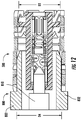
- blind mater interconnect 500 may engage a coaxial transmission medium, for example, a mating (male pin) contact 800 ( FIG. 12 ) having a male outer housing or shroud 802.
- An inner surface of proximal portion 104 and an inner surface of distal portion 108 may each be adapted to engage, for example, circumferentially, an outer surface of mating contact 810 and an inner surface of proximal portion 302 and an inner surface of distal portion 304 of outer conductor 300 may engage an outer surface of male outer housing 802.
- proximal portion 302 and distal portion 304 Prior to engagement with male outer housing 802, proximal portion 302 and distal portion 304 each have an inner width, or diameter, D3 that may be smaller than an outer diameter D4 of male outer housing 802.
- engagement of the inner surface of proximal portion 302 or distal portion 304 with outer surface of male outer housing 802 may cause portions 302 and 304 to flex radially outwardly.
- the inner diameter of proximal portion 302 and/or distal portion 304 may be at least equal to D4 ( FIG. 12 ).
- inner diameter of proximal portion 302 may be approximately equal to D4 upon engagement with male outer housing 802 while distal portion 304 not being engaged to a male outer housing may have an inner diameter of D3 .
- Disengagement of the inner surface of proximal portion 302 and/or distal portion 304 with the outer surface of male outer housing 802 may cause inner diameter of proximal portion 302 and/or distal portion 304 to return to D3.
- D4/D3 may be, in exemplary embodiments, at least 1.05, such as at least 1.1, and further such as at least 1.2, and yet further such as at least 1.3.
- proximal portion 302 and/or distal portion 304 during engagement with male outer housing 802 may result in a radially inward biasing force of outer conductor 300 on male outer housing 802, facilitating transmission of an electrical signal between outer conductor 300 and male outer housing 802 and also reducing the possibility of unwanted disengagement between outer conductor 300 and male outer housing 802.
- mating performance and electrical contact may be improved by increasing the length of cantilevered arms on the socket contact and wrapping the arms around a centroidal axis. This may increase the amount of physical contact of the arm to the coaxial transmission medium and mitigate strain on the arm during deflection, for example, in a mated condition.
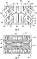
- a socket contact 900 may have a serpentine 902, or undulating pattern that sweeps along the entire length of contact 900. Spaces 904 alternate around the periphery of contact 900, extending from an open side to a closed side uninterrupted, for example, and allowing unhindered expansion under mating conditions.
- another socket contact 920 FIG. 14
- socket contact 900 may reside inside a BMI connector 950 having such an outer conductor 950 and insulators 958 ( FIG. 15 ).
- a socket contact 1000 ( FIG. 16 ), includes a first end 1002, a second end 1004 opposite first end 1002 and a tubular body 1006 between first end 1002 and second end 1004.
- Contact 1000 has a first and a second sloted regions 1008 .
- Each of the first and second slotted regions 1008 has an array of angular cantilevered arms 1010 adjoining an array of slots 1012 and extending from a medial region 1014 to the respective end 1002, 1004.
- Cantilevered arms 1010 define angular cantilevered arms extending at an angle greater than zero degrees to a representative longitudinal axis 1030.
- a flat schematic portion 1001 of a part of contact 1000 for example, sliced longitudinally through medial region 1014 and laid flat, e.g., unrolled, may illustrate the angular nature of angular cantilevered arm 1010.
- Angular slots 1012 may be cut by a cutting means, for example, a laser or electro-mechanical discharge unit or some other suitable cutting means, from first end 1002 to medial region 1014 at an angle 1040 relative to a representative longitudinal axis 1030.
- angular slots 1012 may be, for example, less than 90 degrees relative to axis 1030.
- angular slots 1012 may be, for example, less than 60 degrees, relative to axis 1030, and in yet other examples, angular slots 1012 may be from about 20 degrees to about 30 degrees relative to the axis. By way of example, angular slots 1012 may be about 25 degrees relative to axis 1030.
- Each of the first and second slotted region 1008 defines a first length from the end of slots 1012 proximal to medial region 1014, along axis 1030 that may extend from first end 1002 to second end 1004.
- Each cantilevered arm 1010 defines a second length along cantilevered arm 1010, for example, along an edge 1020 of cantilevered arm 1010, the second length being longer than the first length.
- the second length is from more than 100 percent to about 110 percent of the first length.
- the second length may be about 108% of the first length. Put another way, the second length may be 8% longer than the first length. This improves mating cycle performance.
- Cantilevered arm 1010 having a free end (ends 1002, 1004) and a fixed end (at medial region 1014), may flex along its entire length. As may be appreciated, a longer cantilevered arm may encounter less bending stress along its length than a short cantilevered arm for the same amount of deflection.
- each array of cantilevered arm 1010 wraps around at a steady distance from the centroidal axis of tubular body 1006, as the, respective cantilevered arm 1010 extends from medial region 1014 to the respective, first end 1002 or second end 1004 providing a helical arrangement.
- most of the internal surface of angular cantilevered arm 1010 may be from about 0.0762 mm to 0.127 mm (0.003 inches to about 0.005 inches) from the centroidal axis, and in some embodiments may not deviate from a set distance, or radius, by more than 0.0254 mm (0.001 inches) along the internal surface in an unmated condition.
- Slotted region 1008 may receive, for example, a mating contact pin 820 ( FIGS 18 and 19 ), for example, a coaxial transmission medium, defining a contact region.
- a mating contact pin 820 FIGS 18 and 19
- the length of cantilevered arm 1010 along, for example, edge 1020, that engages pin 820 is longer than an interaction length 1009 by the same relative ratios as the second length to the first length, until interaction length 1009 equals the first length.
- socket contact 1000 may reside inside a BMI connector 1050 having such an outer conductor 1056 and insulators 1058 ( FIG. 20 ) .
Landscapes
- Coupling Device And Connection With Printed Circuit (AREA)
Claims (1)
- Blind-Mate-Verbindung (1050),
wobei die Blind-Mate-Verbindung (1050) einen Außenleiter (1056) aufweist;
wobei die Blind-Mate-Verbindung (1050) einen koaxialen Buchsenkontakt (1000) zum Anschließen an ein koaxiales Übertragungsmedium aufweist, um einen elektrisch leitfähigen Weg zwischen dem Übertragungsmedium und dem koaxialen Buchsenkontakt auszubilden,
wobei der koaxiale Buchsenkontakt (1000) Folgendes aufweist:ein erstes Ende (1002);ein zweites Ende (1004), das dem ersten Ende (1002) entgegengesetzt ist;einen rohrförmigen Körper (1006) zwischen dem ersten Ende (1002) und dem zweiten Ende (1004), wobei der rohrförmige Körper (1006) einen Umfangs- und einen Mittelbereich (1014) aufweist;einen ersten und zweiten Schlitzbereich (1008),wobei der erste Schlitzbereich (1008) mindestens einen Kragarm (1010) aufweist, der sich vom Mittelbereich (1014) zu mindestens dem ersten Ende (1002) erstreckt,wobei der zweite Bereich (1008) mindestens einen Kragarm (1010) aufweist, der sich vom Mittelbereich (1014) zu mindestens dem zweiten Ende (1004) erstreckt;wobei der erste und zweite Schlitzbereich (1008) jeweils eine erste Länge entlang einer Längsachse (1030) definieren, wobei sich die Längsachse (1030) vom ersten Ende (1002) zum zweiten Ende (1004) erstreckt,wobei der mindestens eine Kragarm (1010) jedes des ersten und zweiten Schlitzbereichs (1008) eine zweite Länge entlang des mindestens einen Kragarms (1010) definiert,wobei die zweite Länge länger als die erste Länge ist, um die Steckzyklusleistung zu verbessern,wobei der erste und zweite Schlitzbereich (1008) jeweils eine Anordnung winkeliger Kragarme (1010) aufweist, die an eine Anordnung Schlitze (1012) angrenzt,wobei sich jeder winkelige Kragarm (1010) des ersten Schlitzbereichs (1008) in einem ersten Winkel erstreckt, der größer als Null Grad zur Längsachse (1030) ist,wobei sich jeder winkelige Kragarm (1010) des zweiten Schlitzbereichs (1008) in dem ersten Winkel in Bezug zur Längsachse (1030) erstreckt,wobei sich jede Anordnung winkeliger Kragarme (1010) in einem gleichmäßigen Abstand von einer Schwerpunktachse des rohrförmigen Körpers (1006) windet, während sich der jeweilige Kragarm (1010) vom Mittelbereich (1014) zum jeweiligen Ende (1002, 1004) erstreckt und somit eine schraubenförmige Anordnung vorsieht,wobei der jeweilige Kragarm (1010) ein freies Ende am jeweiligen Ende (1002, 1004) und ein festes Ende am Mittelbereich (1014) aufweist,wobei sich der Außenleiter (1056) im Wesentlichen umlaufend um die Längsachse (1030) erstreckt,
dadurch gekennzeichnet, dass
die zweite Länge mehr als 100 Prozent bis 110 Prozent der ersten Länge beträgt,
die Blind-Mate-Verbindung (1050) einen Isolator (1058) aufweist,
wobei der Außenleiter (1056) eine erste mittige Bohrung definiert, wobei der Isolator (1058) innerhalb der ersten mittigen Bohrung angeordnet ist und sich im Wesentlichen um die Achse (1030) erstreckt,
wobei der Isolator (1058) eine erste Isolatorkomponente und eine zweite Isolatorkomponente aufweist, die zusammenwirken, um eine zweite mittige Bohrung zu definieren, wobei der Buchsenkontakt (1000) innerhalb der zweiten mittigen Bohrung angeordnet ist,
wobei die erste Isolatorkomponente eine Außenfläche, eine Innenfläche und einen verringerten Durchmesserabschnitt aufweist,
wobei die zweite Isolatorkomponente eine Außenfläche, eine Innenfläche und einen verringerten Durchmesserabschnitt aufweist, und
wobei die verringerten Durchmesserabschnitte zulassen, dass der Isolator (1058) den Buchsenkontakt (1000) hält.
Priority Applications (1)
| Application Number | Priority Date | Filing Date | Title |
|---|---|---|---|
| PL12746846T PL2676330T3 (pl) | 2011-02-17 | 2012-02-17 | Połączenie i złącze typu blind-mate |
Applications Claiming Priority (4)
| Application Number | Priority Date | Filing Date | Title |
|---|---|---|---|
| US201161443864P | 2011-02-17 | 2011-02-17 | |
| US201161443858P | 2011-02-17 | 2011-02-17 | |
| US201161443957P | 2011-02-17 | 2011-02-17 | |
| PCT/US2012/025626 WO2012112878A1 (en) | 2011-02-17 | 2012-02-17 | Blind mate interconnect and contact |
Publications (3)
| Publication Number | Publication Date |
|---|---|
| EP2676330A1 EP2676330A1 (de) | 2013-12-25 |
| EP2676330A4 EP2676330A4 (de) | 2015-03-11 |
| EP2676330B1 true EP2676330B1 (de) | 2021-04-28 |
Family
ID=46653108
Family Applications (1)
| Application Number | Title | Priority Date | Filing Date |
|---|---|---|---|
| EP12746846.0A Active EP2676330B1 (de) | 2011-02-17 | 2012-02-17 | Blindsteckbare verbindung und kontakt |
Country Status (5)
| Country | Link |
|---|---|
| US (1) | US8690602B2 (de) |
| EP (1) | EP2676330B1 (de) |
| ES (1) | ES2882854T3 (de) |
| PL (1) | PL2676330T3 (de) |
| WO (1) | WO2012112878A1 (de) |
Families Citing this family (18)
| Publication number | Priority date | Publication date | Assignee | Title |
|---|---|---|---|---|
| US8887388B2 (en) | 2010-11-22 | 2014-11-18 | Andrew Llc | Method for interconnecting a coaxial connector with a solid outer conductor coaxial cable |
| US8365404B2 (en) | 2010-11-22 | 2013-02-05 | Andrew Llc | Method for ultrasonic welding a coaxial cable to a coaxial connector |
| DE202011108052U1 (de) * | 2011-11-18 | 2011-12-06 | Rosenberger Hochfrequenztechnik Gmbh & Co. Kg | Verbindungselement |
| US9490052B2 (en) | 2012-06-29 | 2016-11-08 | Corning Gilbert, Inc. | Tubular insulator for coaxial connector |
| EP2680372B1 (de) * | 2012-06-29 | 2017-06-07 | Corning Optical Communications RF LLC | Isolator mit mehreren Abschnitten für Koaxialstecker |
| US9425548B2 (en) | 2012-11-09 | 2016-08-23 | Commscope Technologies Llc | Resilient coaxial connector interface and method of manufacture |
| US9009960B2 (en) * | 2013-01-25 | 2015-04-21 | Commscope Technologies Llc | Method of manufacturing a curved transition surface of an inner contact |
| US8851933B2 (en) | 2013-03-11 | 2014-10-07 | Kerdea Technologies, Inc. | Releasable electrical connection |
| DE202013002575U1 (de) * | 2013-03-15 | 2013-04-17 | Rosenberger Hochfrequenztechnik Gmbh & Co. Kg | Steckverbinder |
| DE102014007390A1 (de) * | 2014-05-14 | 2015-11-19 | Eisele Pneumatics Gmbh & Co. Kg | Anschlusseinheit für eine Kupplungsvorrichtung, insbesondere eine Mehrfachkupplung |
| US9899787B2 (en) | 2014-07-07 | 2018-02-20 | L-3 Communications Integrated Systems L.P. | Apparatus and methods for connecting and disconnecting threaded connectors |
| TWI649923B (zh) * | 2016-06-17 | 2019-02-01 | 日商阿爾普士電氣股份有限公司 | Crimp type joint and manufacturing method thereof |
| DE102017009066A1 (de) * | 2017-09-28 | 2019-03-28 | Rosenberger Hochfrequenztechnik Gmbh & Co. Kg | Elektrische kontaktvorrichtung |
| EP3499652B1 (de) | 2017-12-18 | 2021-08-18 | Tyco Electronics AMP Korea Co., Ltd. | Verbinderanordnung |
| US10224657B1 (en) * | 2018-01-24 | 2019-03-05 | Te Connectivity Corporation | Spring for use in an RF contact for a plug-in module |
| JP7371465B2 (ja) * | 2019-12-02 | 2023-10-31 | 株式会社オートネットワーク技術研究所 | コネクタおよび端子金具 |
| CN116491029A (zh) * | 2021-03-30 | 2023-07-25 | 上海雷迪埃电子有限公司 | 集成有弹性球形接头链接的用于低互调板对板或板对滤波器射频同轴连接组件的改进的连接器 |
| US12370372B2 (en) | 2021-07-09 | 2025-07-29 | Medtronic, Inc. | Electrical contact for a medical device lead |
Citations (1)
| Publication number | Priority date | Publication date | Assignee | Title |
|---|---|---|---|---|
| US20080194124A1 (en) * | 2006-02-17 | 2008-08-14 | Centipede Systems, Inc. | Socket with high performance electrical connectors |
Family Cites Families (31)
| Publication number | Priority date | Publication date | Assignee | Title |
|---|---|---|---|---|
| FR811272A (fr) | 1936-09-25 | 1937-04-10 | élément de prise de courant | |
| US3314044A (en) | 1964-12-16 | 1967-04-11 | Albert E Powell | Female electrical connectors |
| US3449709A (en) | 1966-11-10 | 1969-06-10 | Hewlett Packard Co | Conductor contact and method of making the same |
| FR2415889A1 (fr) | 1978-01-25 | 1979-08-24 | Bonhomme F R | Perfectionnements apportes aux douilles, pour dispositifs de contact electrique a fiche et douille, et a leurs procedes de fabrication |
| US4518213A (en) | 1983-05-31 | 1985-05-21 | Allied Corporation | One piece hermaphroditic contact for an electrical connector and a method of making the contact |
| US4925403A (en) | 1988-10-11 | 1990-05-15 | Gilbert Engineering Company, Inc. | Coaxial transmission medium connector |
| US5135403A (en) * | 1991-06-07 | 1992-08-04 | Amp Incorporated | Solderless spring socket for printed circuit board |
| US5215481A (en) | 1991-12-13 | 1993-06-01 | Leisey Donald R | Torsion tube electrical connectors |
| US5651699A (en) * | 1994-03-21 | 1997-07-29 | Holliday; Randall A. | Modular connector assembly for coaxial cables |
| US5439393A (en) | 1994-04-18 | 1995-08-08 | Watson; Troy M. | Helical zero insertion force connector for coaxial cables |
| US5807147A (en) | 1997-01-22 | 1998-09-15 | The Whitaker Corporation | Center contact for RF cable |
| TW456609U (en) | 2000-08-21 | 2001-09-21 | Sheng Sheng Entpr Co Ltd | Clamping device of RF transmission cable |
| US6590478B2 (en) * | 2001-03-08 | 2003-07-08 | Lockheed Martin Corporation | Short coaxial transmission line and method for use thereof |
| DE10202637C1 (de) | 2002-01-24 | 2003-08-14 | Ims Connector Systems Gmbh | Steckverbinder |
| US6827608B2 (en) * | 2002-08-22 | 2004-12-07 | Corning Gilbert Inc. | High frequency, blind mate, coaxial interconnect |
| DE10261521B3 (de) | 2002-12-23 | 2004-09-16 | Robert Bosch Gmbh | Hochstromführende Kontaktelemente mit Versatzausgleich |
| US7128604B2 (en) | 2004-06-14 | 2006-10-31 | Corning Gilbert Inc. | High power coaxial interconnect |
| US7077697B2 (en) | 2004-09-09 | 2006-07-18 | Corning Gilbert Inc. | Snap-in float-mount electrical connector |
| US7112078B2 (en) | 2005-02-28 | 2006-09-26 | Gore Enterprise Holdings, Inc. | Gimbling electronic connector |
| US7579550B2 (en) | 2006-03-31 | 2009-08-25 | Boston Scientific Scimed, Inc. | Flexible device shaft with angled spiral wrap |
| US7442045B1 (en) * | 2007-08-17 | 2008-10-28 | Centipede Systems, Inc. | Miniature electrical ball and tube socket with self-capturing multiple-contact-point coupling |
| WO2009119904A1 (ja) * | 2008-03-28 | 2009-10-01 | 日本電気株式会社 | 半導体装置、その製造方法、プリント回路基板および電子機器 |
| US7892004B2 (en) | 2008-04-17 | 2011-02-22 | Tyco Electronics Corporation | Connector having a sleeve member |
| DE202008011118U1 (de) | 2008-08-21 | 2008-10-30 | Centipede Systems, Inc., San Jose | Doppelendiger mikroelektronischer Verbinder |
| DE202008011119U1 (de) | 2008-08-21 | 2008-10-30 | Centipede Systems, Inc., San Jose | Elastischer mikroelektronischer Verbinder |
| USD595653S1 (en) * | 2008-08-29 | 2009-07-07 | Centipede Systems, Inc. | Double ended resilient microelectronic connector |
| US20100304579A1 (en) * | 2009-05-26 | 2010-12-02 | Brian Lyle Kisling | Low Resistance Connector For Printed Circuit Board |
| US8317539B2 (en) | 2009-08-14 | 2012-11-27 | Corning Gilbert Inc. | Coaxial interconnect and contact |
| US8597050B2 (en) | 2009-12-21 | 2013-12-03 | Corning Gilbert Inc. | Digital, small signal and RF microwave coaxial subminiature push-on differential pair system |
| WO2011123225A1 (en) | 2010-03-29 | 2011-10-06 | Corning Gilbert Inc. | Digital, small signal and rf microwave coaxial subminiature push-on differential pair system |
| WO2011123226A1 (en) | 2010-03-29 | 2011-10-06 | Corning Gilbert Inc. | Digital, small signal and rf microwave coaxial subminiature push-on differential pair system |
-
2012
- 2012-02-17 ES ES12746846T patent/ES2882854T3/es active Active
- 2012-02-17 WO PCT/US2012/025626 patent/WO2012112878A1/en not_active Ceased
- 2012-02-17 EP EP12746846.0A patent/EP2676330B1/de active Active
- 2012-02-17 PL PL12746846T patent/PL2676330T3/pl unknown
- 2012-02-17 US US13/399,396 patent/US8690602B2/en active Active
Patent Citations (1)
| Publication number | Priority date | Publication date | Assignee | Title |
|---|---|---|---|---|
| US20080194124A1 (en) * | 2006-02-17 | 2008-08-14 | Centipede Systems, Inc. | Socket with high performance electrical connectors |
Also Published As
| Publication number | Publication date |
|---|---|
| ES2882854T3 (es) | 2021-12-02 |
| US8690602B2 (en) | 2014-04-08 |
| PL2676330T3 (pl) | 2021-11-29 |
| WO2012112878A1 (en) | 2012-08-23 |
| EP2676330A4 (de) | 2015-03-11 |
| EP2676330A1 (de) | 2013-12-25 |
| US20120214357A1 (en) | 2012-08-23 |
Similar Documents
| Publication | Publication Date | Title |
|---|---|---|
| EP2676330B1 (de) | Blindsteckbare verbindung und kontakt | |
| EP2490304B1 (de) | Koaxialblindverbinder und Aussenleiter für einen Blindverbinder | |
| EP2680372B1 (de) | Isolator mit mehreren Abschnitten für Koaxialstecker | |
| EP2680371B1 (de) | Rohrförmiges Isolierstück für Koaxialstecker | |
| EP2465167B1 (de) | Koaxialverbindung und kontakt | |
| US5474470A (en) | Compensated interface coaxial connector apparatus | |
| US5217391A (en) | Matable coaxial connector assembly having impedance compensation | |
| US6102746A (en) | Coaxial electrical connector with resilient conductive wires | |
| CN110582899A (zh) | 连接器的接触元件 | |
| EP2027630B1 (de) | Koaxialstecker | |
| US11799243B2 (en) | Electrical connector assembly with RF impedance element | |
| CN112787121A (zh) | 同轴连接器及板对板连接器组件 | |
| US4397515A (en) | Center conductor element for female microwave coaxial connector | |
| KR102583433B1 (ko) | 저비용 자기적응형 보드 투 보드 무선 주파수 동축 커넥터 | |
| CN210866559U (zh) | 同轴连接器及板对板连接器组件 | |
| KR20260027906A (ko) | 높은 전류 용량을 갖춘 신뢰적인 적응성 전기 커넥터 | |
| GB2064234A (en) | Improved centre conductor element for female microwave coaxial connector |
Legal Events
| Date | Code | Title | Description |
|---|---|---|---|
| PUAI | Public reference made under article 153(3) epc to a published international application that has entered the european phase |
Free format text: ORIGINAL CODE: 0009012 |
|
| 17P | Request for examination filed |
Effective date: 20130902 |
|
| AK | Designated contracting states |
Kind code of ref document: A1 Designated state(s): AL AT BE BG CH CY CZ DE DK EE ES FI FR GB GR HR HU IE IS IT LI LT LU LV MC MK MT NL NO PL PT RO RS SE SI SK SM TR |
|
| DAX | Request for extension of the european patent (deleted) | ||
| A4 | Supplementary search report drawn up and despatched |
Effective date: 20150206 |
|
| RIC1 | Information provided on ipc code assigned before grant |
Ipc: H01R 13/631 20060101ALI20150202BHEP Ipc: H01R 13/11 20060101AFI20150202BHEP |
|
| STAA | Information on the status of an ep patent application or granted ep patent |
Free format text: STATUS: EXAMINATION IS IN PROGRESS |
|
| 17Q | First examination report despatched |
Effective date: 20170329 |
|
| GRAP | Despatch of communication of intention to grant a patent |
Free format text: ORIGINAL CODE: EPIDOSNIGR1 |
|
| STAA | Information on the status of an ep patent application or granted ep patent |
Free format text: STATUS: GRANT OF PATENT IS INTENDED |
|
| INTG | Intention to grant announced |
Effective date: 20201116 |
|
| RAP1 | Party data changed (applicant data changed or rights of an application transferred) |
Owner name: CORNING OPTICAL COMMUNICATIONS RF LLC |
|
| GRAS | Grant fee paid |
Free format text: ORIGINAL CODE: EPIDOSNIGR3 |
|
| GRAA | (expected) grant |
Free format text: ORIGINAL CODE: 0009210 |
|
| STAA | Information on the status of an ep patent application or granted ep patent |
Free format text: STATUS: THE PATENT HAS BEEN GRANTED |
|
| AK | Designated contracting states |
Kind code of ref document: B1 Designated state(s): AL AT BE BG CH CY CZ DE DK EE ES FI FR GB GR HR HU IE IS IT LI LT LU LV MC MK MT NL NO PL PT RO RS SE SI SK SM TR |
|
| REG | Reference to a national code |
Ref country code: GB Ref legal event code: FG4D |
|
| REG | Reference to a national code |
Ref country code: CH Ref legal event code: EP |
|
| REG | Reference to a national code |
Ref country code: DE Ref legal event code: R096 Ref document number: 602012075387 Country of ref document: DE |
|
| REG | Reference to a national code |
Ref country code: AT Ref legal event code: REF Ref document number: 1388180 Country of ref document: AT Kind code of ref document: T Effective date: 20210515 |
|
| REG | Reference to a national code |
Ref country code: IE Ref legal event code: FG4D |
|
| REG | Reference to a national code |
Ref country code: NL Ref legal event code: FP |
|
| REG | Reference to a national code |
Ref country code: LT Ref legal event code: MG9D |
|
| REG | Reference to a national code |
Ref country code: AT Ref legal event code: MK05 Ref document number: 1388180 Country of ref document: AT Kind code of ref document: T Effective date: 20210428 |
|
| PG25 | Lapsed in a contracting state [announced via postgrant information from national office to epo] |
Ref country code: HR Free format text: LAPSE BECAUSE OF FAILURE TO SUBMIT A TRANSLATION OF THE DESCRIPTION OR TO PAY THE FEE WITHIN THE PRESCRIBED TIME-LIMIT Effective date: 20210428 Ref country code: AT Free format text: LAPSE BECAUSE OF FAILURE TO SUBMIT A TRANSLATION OF THE DESCRIPTION OR TO PAY THE FEE WITHIN THE PRESCRIBED TIME-LIMIT Effective date: 20210428 Ref country code: BG Free format text: LAPSE BECAUSE OF FAILURE TO SUBMIT A TRANSLATION OF THE DESCRIPTION OR TO PAY THE FEE WITHIN THE PRESCRIBED TIME-LIMIT Effective date: 20210728 Ref country code: FI Free format text: LAPSE BECAUSE OF FAILURE TO SUBMIT A TRANSLATION OF THE DESCRIPTION OR TO PAY THE FEE WITHIN THE PRESCRIBED TIME-LIMIT Effective date: 20210428 Ref country code: LT Free format text: LAPSE BECAUSE OF FAILURE TO SUBMIT A TRANSLATION OF THE DESCRIPTION OR TO PAY THE FEE WITHIN THE PRESCRIBED TIME-LIMIT Effective date: 20210428 |
|
| PG25 | Lapsed in a contracting state [announced via postgrant information from national office to epo] |
Ref country code: PT Free format text: LAPSE BECAUSE OF FAILURE TO SUBMIT A TRANSLATION OF THE DESCRIPTION OR TO PAY THE FEE WITHIN THE PRESCRIBED TIME-LIMIT Effective date: 20210830 Ref country code: NO Free format text: LAPSE BECAUSE OF FAILURE TO SUBMIT A TRANSLATION OF THE DESCRIPTION OR TO PAY THE FEE WITHIN THE PRESCRIBED TIME-LIMIT Effective date: 20210728 Ref country code: GR Free format text: LAPSE BECAUSE OF FAILURE TO SUBMIT A TRANSLATION OF THE DESCRIPTION OR TO PAY THE FEE WITHIN THE PRESCRIBED TIME-LIMIT Effective date: 20210729 Ref country code: IS Free format text: LAPSE BECAUSE OF FAILURE TO SUBMIT A TRANSLATION OF THE DESCRIPTION OR TO PAY THE FEE WITHIN THE PRESCRIBED TIME-LIMIT Effective date: 20210828 Ref country code: LV Free format text: LAPSE BECAUSE OF FAILURE TO SUBMIT A TRANSLATION OF THE DESCRIPTION OR TO PAY THE FEE WITHIN THE PRESCRIBED TIME-LIMIT Effective date: 20210428 Ref country code: SE Free format text: LAPSE BECAUSE OF FAILURE TO SUBMIT A TRANSLATION OF THE DESCRIPTION OR TO PAY THE FEE WITHIN THE PRESCRIBED TIME-LIMIT Effective date: 20210428 Ref country code: RS Free format text: LAPSE BECAUSE OF FAILURE TO SUBMIT A TRANSLATION OF THE DESCRIPTION OR TO PAY THE FEE WITHIN THE PRESCRIBED TIME-LIMIT Effective date: 20210428 |
|
| REG | Reference to a national code |
Ref country code: ES Ref legal event code: FG2A Ref document number: 2882854 Country of ref document: ES Kind code of ref document: T3 Effective date: 20211202 |
|
| PG25 | Lapsed in a contracting state [announced via postgrant information from national office to epo] |
Ref country code: RO Free format text: LAPSE BECAUSE OF FAILURE TO SUBMIT A TRANSLATION OF THE DESCRIPTION OR TO PAY THE FEE WITHIN THE PRESCRIBED TIME-LIMIT Effective date: 20210428 Ref country code: EE Free format text: LAPSE BECAUSE OF FAILURE TO SUBMIT A TRANSLATION OF THE DESCRIPTION OR TO PAY THE FEE WITHIN THE PRESCRIBED TIME-LIMIT Effective date: 20210428 Ref country code: CZ Free format text: LAPSE BECAUSE OF FAILURE TO SUBMIT A TRANSLATION OF THE DESCRIPTION OR TO PAY THE FEE WITHIN THE PRESCRIBED TIME-LIMIT Effective date: 20210428 Ref country code: DK Free format text: LAPSE BECAUSE OF FAILURE TO SUBMIT A TRANSLATION OF THE DESCRIPTION OR TO PAY THE FEE WITHIN THE PRESCRIBED TIME-LIMIT Effective date: 20210428 Ref country code: SK Free format text: LAPSE BECAUSE OF FAILURE TO SUBMIT A TRANSLATION OF THE DESCRIPTION OR TO PAY THE FEE WITHIN THE PRESCRIBED TIME-LIMIT Effective date: 20210428 Ref country code: SM Free format text: LAPSE BECAUSE OF FAILURE TO SUBMIT A TRANSLATION OF THE DESCRIPTION OR TO PAY THE FEE WITHIN THE PRESCRIBED TIME-LIMIT Effective date: 20210428 |
|
| REG | Reference to a national code |
Ref country code: DE Ref legal event code: R097 Ref document number: 602012075387 Country of ref document: DE |
|
| PLBE | No opposition filed within time limit |
Free format text: ORIGINAL CODE: 0009261 |
|
| STAA | Information on the status of an ep patent application or granted ep patent |
Free format text: STATUS: NO OPPOSITION FILED WITHIN TIME LIMIT |
|
| PGFP | Annual fee paid to national office [announced via postgrant information from national office to epo] |
Ref country code: PL Payment date: 20211217 Year of fee payment: 11 |
|
| 26N | No opposition filed |
Effective date: 20220131 |
|
| PG25 | Lapsed in a contracting state [announced via postgrant information from national office to epo] |
Ref country code: IS Free format text: LAPSE BECAUSE OF FAILURE TO SUBMIT A TRANSLATION OF THE DESCRIPTION OR TO PAY THE FEE WITHIN THE PRESCRIBED TIME-LIMIT Effective date: 20210828 Ref country code: AL Free format text: LAPSE BECAUSE OF FAILURE TO SUBMIT A TRANSLATION OF THE DESCRIPTION OR TO PAY THE FEE WITHIN THE PRESCRIBED TIME-LIMIT Effective date: 20210428 |
|
| PGFP | Annual fee paid to national office [announced via postgrant information from national office to epo] |
Ref country code: ES Payment date: 20220310 Year of fee payment: 11 |
|
| PG25 | Lapsed in a contracting state [announced via postgrant information from national office to epo] |
Ref country code: IT Free format text: LAPSE BECAUSE OF FAILURE TO SUBMIT A TRANSLATION OF THE DESCRIPTION OR TO PAY THE FEE WITHIN THE PRESCRIBED TIME-LIMIT Effective date: 20210428 |
|
| PG25 | Lapsed in a contracting state [announced via postgrant information from national office to epo] |
Ref country code: MC Free format text: LAPSE BECAUSE OF FAILURE TO SUBMIT A TRANSLATION OF THE DESCRIPTION OR TO PAY THE FEE WITHIN THE PRESCRIBED TIME-LIMIT Effective date: 20210428 |
|
| REG | Reference to a national code |
Ref country code: CH Ref legal event code: PL |
|
| REG | Reference to a national code |
Ref country code: BE Ref legal event code: MM Effective date: 20220228 |
|
| PG25 | Lapsed in a contracting state [announced via postgrant information from national office to epo] |
Ref country code: LU Free format text: LAPSE BECAUSE OF NON-PAYMENT OF DUE FEES Effective date: 20220217 |
|
| PG25 | Lapsed in a contracting state [announced via postgrant information from national office to epo] |
Ref country code: LI Free format text: LAPSE BECAUSE OF NON-PAYMENT OF DUE FEES Effective date: 20220228 Ref country code: IE Free format text: LAPSE BECAUSE OF NON-PAYMENT OF DUE FEES Effective date: 20220217 Ref country code: CH Free format text: LAPSE BECAUSE OF NON-PAYMENT OF DUE FEES Effective date: 20220228 |
|
| PG25 | Lapsed in a contracting state [announced via postgrant information from national office to epo] |
Ref country code: BE Free format text: LAPSE BECAUSE OF NON-PAYMENT OF DUE FEES Effective date: 20220228 |
|
| PG25 | Lapsed in a contracting state [announced via postgrant information from national office to epo] |
Ref country code: HU Free format text: LAPSE BECAUSE OF FAILURE TO SUBMIT A TRANSLATION OF THE DESCRIPTION OR TO PAY THE FEE WITHIN THE PRESCRIBED TIME-LIMIT; INVALID AB INITIO Effective date: 20120217 |
|
| REG | Reference to a national code |
Ref country code: ES Ref legal event code: FD2A Effective date: 20240405 |
|
| PG25 | Lapsed in a contracting state [announced via postgrant information from national office to epo] |
Ref country code: ES Free format text: LAPSE BECAUSE OF NON-PAYMENT OF DUE FEES Effective date: 20230218 |
|
| PG25 | Lapsed in a contracting state [announced via postgrant information from national office to epo] |
Ref country code: MK Free format text: LAPSE BECAUSE OF FAILURE TO SUBMIT A TRANSLATION OF THE DESCRIPTION OR TO PAY THE FEE WITHIN THE PRESCRIBED TIME-LIMIT Effective date: 20210428 Ref country code: ES Free format text: LAPSE BECAUSE OF NON-PAYMENT OF DUE FEES Effective date: 20230218 Ref country code: CY Free format text: LAPSE BECAUSE OF FAILURE TO SUBMIT A TRANSLATION OF THE DESCRIPTION OR TO PAY THE FEE WITHIN THE PRESCRIBED TIME-LIMIT Effective date: 20210428 |
|
| PG25 | Lapsed in a contracting state [announced via postgrant information from national office to epo] |
Ref country code: MT Free format text: LAPSE BECAUSE OF FAILURE TO SUBMIT A TRANSLATION OF THE DESCRIPTION OR TO PAY THE FEE WITHIN THE PRESCRIBED TIME-LIMIT Effective date: 20210428 |
|
| PG25 | Lapsed in a contracting state [announced via postgrant information from national office to epo] |
Ref country code: PL Free format text: LAPSE BECAUSE OF NON-PAYMENT OF DUE FEES Effective date: 20230217 |
|
| PG25 | Lapsed in a contracting state [announced via postgrant information from national office to epo] |
Ref country code: PL Free format text: LAPSE BECAUSE OF NON-PAYMENT OF DUE FEES Effective date: 20230217 |
|
| PGFP | Annual fee paid to national office [announced via postgrant information from national office to epo] |
Ref country code: NL Payment date: 20250114 Year of fee payment: 14 |
|
| PG25 | Lapsed in a contracting state [announced via postgrant information from national office to epo] |
Ref country code: TR Free format text: LAPSE BECAUSE OF FAILURE TO SUBMIT A TRANSLATION OF THE DESCRIPTION OR TO PAY THE FEE WITHIN THE PRESCRIBED TIME-LIMIT Effective date: 20210428 |
|
| PGFP | Annual fee paid to national office [announced via postgrant information from national office to epo] |
Ref country code: GB Payment date: 20260113 Year of fee payment: 15 |
|
| PGFP | Annual fee paid to national office [announced via postgrant information from national office to epo] |
Ref country code: DE Payment date: 20260115 Year of fee payment: 15 |
|
| PGFP | Annual fee paid to national office [announced via postgrant information from national office to epo] |
Ref country code: FR Payment date: 20260109 Year of fee payment: 15 |