EP2676377B1 - Récepteur de satellite à annulation de signal brouilleur - Google Patents
Récepteur de satellite à annulation de signal brouilleur Download PDFInfo
- Publication number
- EP2676377B1 EP2676377B1 EP12747383.3A EP12747383A EP2676377B1 EP 2676377 B1 EP2676377 B1 EP 2676377B1 EP 12747383 A EP12747383 A EP 12747383A EP 2676377 B1 EP2676377 B1 EP 2676377B1
- Authority
- EP
- European Patent Office
- Prior art keywords
- receiver
- output
- signal
- channel
- interference
- Prior art date
- Legal status (The legal status is an assumption and is not a legal conclusion. Google has not performed a legal analysis and makes no representation as to the accuracy of the status listed.)
- Active
Links
Images



Classifications
-
- H—ELECTRICITY
- H04—ELECTRIC COMMUNICATION TECHNIQUE
- H04B—TRANSMISSION
- H04B7/00—Radio transmission systems, i.e. using radiation field
- H04B7/02—Diversity systems; Multi-antenna system, i.e. transmission or reception using multiple antennas
- H04B7/04—Diversity systems; Multi-antenna system, i.e. transmission or reception using multiple antennas using two or more spaced independent antennas
- H04B7/08—Diversity systems; Multi-antenna system, i.e. transmission or reception using multiple antennas using two or more spaced independent antennas at the receiving station
- H04B7/0837—Diversity systems; Multi-antenna system, i.e. transmission or reception using multiple antennas using two or more spaced independent antennas at the receiving station using pre-detection combining
- H04B7/0842—Weighted combining
- H04B7/0845—Weighted combining per branch equalization, e.g. by an FIR-filter or RAKE receiver per antenna branch
-
- H—ELECTRICITY
- H04—ELECTRIC COMMUNICATION TECHNIQUE
- H04B—TRANSMISSION
- H04B1/00—Details of transmission systems, not covered by a single one of groups H04B3/00 - H04B13/00; Details of transmission systems not characterised by the medium used for transmission
- H04B1/06—Receivers
- H04B1/10—Means associated with receiver for limiting or suppressing noise or interference
- H04B1/109—Means associated with receiver for limiting or suppressing noise or interference by improving strong signal performance of the receiver when strong unwanted signals are present at the receiver input
-
- H—ELECTRICITY
- H04—ELECTRIC COMMUNICATION TECHNIQUE
- H04B—TRANSMISSION
- H04B1/00—Details of transmission systems, not covered by a single one of groups H04B3/00 - H04B13/00; Details of transmission systems not characterised by the medium used for transmission
- H04B1/06—Receivers
- H04B1/10—Means associated with receiver for limiting or suppressing noise or interference
- H04B1/12—Neutralising, balancing, or compensation arrangements
- H04B1/123—Neutralising, balancing, or compensation arrangements using adaptive balancing or compensation means
- H04B1/126—Neutralising, balancing, or compensation arrangements using adaptive balancing or compensation means having multiple inputs, e.g. auxiliary antenna for receiving interfering signal
Definitions
- the present invention relates generally to communication systems, and particularly to methods and systems for interference cancellation in communication receivers.
- Wireless communication systems are sometimes allocated shared or overlapping frequency bands. Overlapping allocations of this sort may cause interference from one communication system to another. For example, a terrestrial cellular system may cause interference to satellite communication receivers that operate in overlapping channels.
- U.S. Patent Application Publication 2002/0110206 describes a combined interference cancellation communication system for satellite communications.
- a receiver receives a waveform having data information and noise information.
- a filter bank is coupled with the receiver to receive and filter waveform and output channel information received by the receiver.
- a demodulator provides an estimation signal representative of an estimation of at least one parameter of the channel information.
- Soft-input and soft-output decoders are provided to receive the channel information in order to calculate and estimate interference values based on the estimation signal.
- a soft-input and soft-output interference canceller receives the output channel information and the estimated interference value calculated from the decoders in order to provide a data signal substantially without interference.
- U.S. Patent Application Publications 2004/0042569 and 2007/0098121 describe an interference signal canceling system for canceling interference signals from earth station received signals using a two input adaptive cancellation network.
- Main and auxiliary signals are derived directly or by coherent conversion to intermediate frequency using an auxiliary antenna, cross-polarized feed, or auxiliary squinted feed.
- Filters set receive and canceling bands.
- Cancellation combines the main signal with a phase, amplitude and time modulated sample of the auxiliary signal.
- a receiver correlates the auxiliary signal with a sample of the combined output to minimize interference.
- U.S. Patent Application Publication 2009/0102706 describes a satellite interference canceling system that cancels interference between two or more signals received by a satellite receiver. Gain and phase are applied to the received signals and then combined with the other signals to result in cancellation by subtraction. The gain and phase values needed to cancel the interference are derived from measurements of Carrier-to-Noise ratio (C/N) as an indication of the interference level.
- C/N Carrier-to-Noise ratio
- U.S. Patent 6,597,750 describes a system for receiving multiple broadcast channels transmitted with different polarizations.
- the system includes a first demodulator for demodulating a first channel having a first polarization to produce a first demodulated channel signal, and a second demodulator for demodulating a second channel having a second polarization, opposite to the first polarization, to produce a second demodulated channel signal.
- An adaptive interference cancellation network coupled to the first and second demodulators, cancels interference, derived from the second channel, in the first demodulated channel signal to produce a received signal.
- Verdu describes successive interference cancellation processes, in " Multiuser Detection,” Cambridge University Press, November, 1998, chapter 7 .
- U.S. Patent Application Publication 2009/0086863 describes techniques for detecting and mitigating interference.
- a device senses interference levels and digitally reconstructs the expected interference in the received signal.
- the device may correlate the reconstructed interference with the received signal and determine interference in the received signal based on correlation results.
- the device may adjust the operation of one or more circuit blocks in a receiver based on the detected interference in the received signal.
- the device may condition the digital interference to obtain conditioned reconstructed interference matching the interference in the received signal and may then subtract the conditioned interference from the received signal.
- U.S. Patent Application Publication 2008/0273552 describes a wideband telecommunications device with narrow band support.
- the device may be a receiver having a wireless interface configured to receive combined first and second signals, the first signal having data in a first frequency band and the second signal having data in a second frequency band wider than the first frequency band, wherein the first frequency band is within the second frequency band.
- the receiver may also be a processing system configured to recover the data in the first signal from the combined first and second signals.
- the document specifically describes recovering a Bluetooth signal with a wideband OFDM receiver without interference from the OFDM signal without the need for a separate Bluetooth transmitter or receiver.
- U.S. Patent Application Publication 2002/0098802 describes a mobile satellite communications system comprising a ground station including a first air interface circuit operative to communicate with a satellite according to a first air interface standard and a second air interface circuit operative to communicate with the satellite according to a second air interface standard.
- the first and second air interface circuit may be included in a gateway that further comprises a telecommunications switch operative to transfer information between the first and second air interface circuits and/or between respective ones of the first and second air interface circuits and an external communications system.
- the first air interface standard may be a "native" standard used by the mobile satellite communications system
- the second air interface standard may be an air interface standard native to a second mobile satellite communications system, for example, a neighboring system having users that may intermittently travel into the coverage area of the first mobile satellite communications system.
- U.S. Patent Application Publication 2003/0054762 describes satellite radiotelephone systems and communications methods that include a space-based component and a synchronizable ancillary terrestrial network that are configured to communicate with radiotelephones.
- the space-based component and ancillary terrestrial network are configured to communicate with a first radiotelephone in a first satellite cell over a first frequency band and/or a first air interface, and to communicate with a second radiotelephone in the first or a second satellite cell over a second frequency band and/or a second air interface.
- An interference reducer is included reduce the interference from wireless communications received by the space-based component.
- the interference reducer generates an interference cancellation signal that comprises a delayed replica of the wireless communications undesirably received by the space-based component. The delayed replica is then subtracted from the wireless communications received from the space-based component.
- An embodiment of the present invention that is described herein provides a method for communication.
- the method includes receiving a Radio Frequency (RF) channel, which contains a desired signal conforming to a first air interface and an interfering signal conforming to a second air interface that is different from the first air interface, by a first receiver that is configured for the first air interface and receives the RF channel via a first antenna, and by a second receiver that is configured for the second air interface and receives the RF channel via a second antenna that is different from the first antenna.
- the first receiver and the second receiver are synchronized to a common frequency and timing reference, even though the first receiver and the second receiver are configured for difference air interfaces.
- the desired signal is decoded from the RF channel using the first receiver to generate a first output
- the interfering signal is decoded from the RF channel using the second receiver to generate a second output
- the desired signal is reconstructed while suppressing the interfering signal by jointly processing the first and second outputs.
- jointly processing the first and second outputs includes processing the second output so as to generate an adjusted second output that matches the first output in time and frequency, and combining the adjusted second output with the first output.
- Processing the second output may include accepting from the first and second receivers timing and frequency estimates regarding the desired signal and the interfering signal, respectively, and adjusting the second output based on the timing and frequency estimates.
- jointly processing the first and second outputs further includes processing the first output so as to generate an adjusted first output that matches the second output in time and frequency, and combining the adjusted first output with the second output.
- Jointly processing the first and second outputs includes evaluating a selection criterion in order to select between (i) a first order, in which the adjusted first output is initially generated and combined with the second output, and then the adjusted second output is generated and combined with the first output; and (ii) a second order, in which the adjusted second output is initially generated and combined with the first output, and then the adjusted first output is generated and combined with the second output.
- jointly processing the first and second outputs includes alternating between adjustment of the first output and adjustment of the second output until meeting a termination criterion.
- decoding the desired signal includes producing a first weighted sum of multiple replicas of the RF channel received via multiple respective antennas and providing the first weighted sum as input to the first receiver
- decoding the interfering signal includes producing a second weighted sum of the multiple replicas of the RF channel and providing the second weighted sum as input to the second receiver.
- reconstructing the desired signal includes extracting the interfering signal from an extraction point selected from a group of extraction points in the second receiver, and removing the extracted interfering signal from the desired signal at a cancellation point selected from a set of cancellation points in the first receiver.
- the desired signal is received from a satellite
- the interfering signal is received from a terrestrial communication system.
- receiving the RF channel includes receiving two or more interfering signals in addition to the desired signal
- decoding the interfering signal includes decoding the two or more interfering signals using two or more respective second receivers that are synchronized to the common frequency and timing reference, to produce two or more second outputs
- jointly processing the first and second outputs includes reconstructing the desired signal while suppressing the two or more interfering signals.
- jointly processing the first and second outputs includes selecting an order among the second outputs based on an ordering criterion, and combining the second outputs with the desired signal in accordance with the selected order.
- a communication apparatus including a front end, first and second antennas, first and second receivers, a reference unit and an interference generation unit.
- the front end is configured to receive a Radio Frequency (RF) channel containing a desired signal conforming to a first air interface and an interfering signal conforming to a second air interface that is different from the first air interface.
- the first receiver configured for the first air interface and to receive the RF channel via the first antenna, is configured to reconstruct the desired signal from the RF channel by decoding the first air interface, to produce a first output.
- RF Radio Frequency
- the second receiver configured for the second air interface and to receive the RF channel via the second antenna, is configured to reconstruct the interfering signal from the RF channel by decoding the second air interface, to produce a second output.
- the reference unit is configured to synchronize the first and second receivers to a common frequency and timing reference, even though the first receiver and the second receiver are configured for difference air interfaces.
- the interference regeneration unit is configured to provide the second output to the first receiver, and to cause the first receiver to reconstruct the desired signal while suppressing the interfering signal.
- transmissions of one system may cause interference in a receiver of the other system.
- WiMAX networks and direct-to-home satellite systems are allocated overlapping spectra.
- a satellite receiver may suffer interference from a nearby WiMAX base station.
- Embodiments of the present invention that are described herein provide improved methods and systems for reducing interference in communication receivers.
- the embodiments described herein refer mainly to reduction of interference in satellite terminals that is caused by cellular base stations.
- the disclosed techniques can be used with any suitable desired signal and any suitable interfering signal.
- an interference-canceling receiver receives a desired signal and an interfering signal having respective (possibly different) air interfaces.
- the interference-canceling receiver comprises two receivers - a first receiver designed to decode the air interface of the desired signal, and a second receiver designed to decode the air interface of the interfering signal.
- the first receiver attempts to decode the desired signal in the presence of interfering signal components, while the second receiver attempts to decode the interfering signal (possibly in the presence of desired signal components).
- the interference-canceling receiver is able to reconstruct the desired signal while suppressing the interference from the interfering signal.
- both receivers are synchronized to the same frequency and timing clock reference, even though the receivers are designed for different air interfaces.
- joint processing of the receiver outputs e.g., subtraction of the output of the second receiver from the output of the first receiver
- the two receivers carry out a successive cancellation process in which each receiver refines the decoding of its respective signal based on the output of the other receiver.
- the methods and systems described herein are highly effective in recovering the desired signal, even when it is considerably weaker than the interfering signal.
- the disclosed techniques are also useful for joint decoding of multiple desired signals that overlap in frequency, for example satellite signals having different (e.g., orthogonal) polarities that suffer from mutual interference due to cross-polarization leakage.
- the disclosed techniques increase the spectral efficiency and capacity of wireless communication systems.
- the techniques described herein can be used in existing receiver designs with minimal modifications, e.g., by reusing existing timing and frequency offset estimation mechanisms.
- Fig. 1 is a block diagram that schematically illustrates a satellite communication system 20 that applies interference cancellation, in accordance with an embodiment of the present invention.
- a satellite transmitter 24 transmits an uplink Radio Frequency (RF) signal toward a satellite 32 using an antenna 28.
- the satellite converts this signal into a downlink RF signal, and transmits the downlink signal to an interference-canceling receiver 36.
- Receiver 36 is designed to receive the downlink signal (also referred to as a desired signal) while canceling interference caused by interfering signals.
- the interfering signal originates from a nearby WiMAX (IEEE 802.16) base station 40.
- WiMAX IEEE 802.6
- the desired signal and the interfering signal are assumed to originate from systems that overlap, at least partially, in frequency.
- C-band frequencies in the range 3.65-3.70GHz are sometimes allocated to direct-to-home satellite services and to WimMAX or Broadband Wireless Access (BWA) terrestrial systems in the same geographical regions.
- BWA Broadband Wireless Access
- a satellite reception terminal may suffer from interference from a nearby WiMAX base station or mobile station.
- the interfering signal may alternatively comprise a Long Term Evolution (LTE) signal, a Wireless Local Area Network (WLAN) signal such as WiFi, a cordless phone signal, or any other suitable signal type.
- LTE Long Term Evolution
- WLAN Wireless Local Area Network
- the interfering signal may comprise another satellite signal, e.g., a signal originating from the same satellite transponder as the desired signal or from another transponder, a signal having orthogonal polarity relative to the desired signal.
- the desired and interfering signals may be produced by any other suitable systems and may operate in any other suitable frequency band.
- the source of the interfering signal need not necessarily be adjacent to receiver 36.
- Interference-canceling receiver 36 comprises one or more receive antennas 44, each of which receives the desired and/or interfering signals.
- one of antennas 44 comprises a directional antenna (e.g., dish) that is pointed toward satellite 32 in order to receive the desired signal, but nevertheless receives the interfering signal to some extent.
- one of antennas 44 receives only the interfering signal and not the desired signal.
- each of antennas 44 receives both the desired signal and the interfering signal to some extent.
- receiver 36 comprises only a single antenna 44. The antennas may be collocated or located at different locations. Further alternatively, any other suitable configuration of one or more antennas 44 can be used.
- a receiver (RX) front end 48 receives the signals from antennas 44 and extracts the appropriate RF channel or channels. Typically, the front end performs low-noise amplification, down-conversion to Intermediate Frequency (IF) and tuning to the desired channel or channels. Respective outputs of front end 48 are provided to a desired signal receiver 52 and to an interfering signal receiver 56. Receivers 52 and 56 may be collocated or separate.
- air interface refers to the physical-layer signals and protocols that are used for encoding, modulation and transmission.
- the air interface also sometimes referred to as "physical layer” or “PHY” typically defines features such as pulse shape, modulation scheme, Forward Error Correction (FEC), channel multiplexing scheme and radio channel structure of the signal.
- FEC Forward Error Correction
- Desired signal receiver 52 is designed to decode the air interface of the desired signal
- interfering signal receiver 56 is designed to decode the air interface of the interfering signal.
- Receiver 52 comprises a satellite receiver that complies with the air interface used by transmitter 24, such as a Digital Video Broadcasting - Second Generation (DVB-S2) receiver, or a receiver of any other suitable air interface.
- Receiver 56 may comprise a WiMAX receiver, or a Receiver of any other suitable air interface.
- the modulation type may comprise a certain single-carrier modulation, Orthogonal Frequency Division Multiplexing (OFDM), Orthogonal Frequency Division Multiple Access (OFDMA), spread-spectrum modulation, or any other suitable modulation type.
- OFDM Orthogonal Frequency Division Multiplexing
- OFDMA Orthogonal Frequency Division Multiple Access
- the air interfaces in any of the two receivers may specify continuous transmission or transmission in bursts.
- receivers 52 and 56 are synchronized to the same frequency and timing reference.
- receiver 52 cancels the interference that is caused by the interfering signal.
- receiver 52 cancels the interference by combining (e.g., adding or subtracting) a version of the interfering signal, as produced by receiver 56, with the desired signal.
- receivers 52 and 56 carry out a successive decoding process in which each receiver refines the decoding of its respective signal based on the output of the other receiver.
- receiver 52 may refine the decoding of the desired signal based on the decoded interfering signal produced by receiver 56
- receiver 56 may refine the decoding of the interfering signal based on the decoded desired signal produced by receiver 52. Any suitable number of decoding iterations, and possibly only a single refinement, may be performed.
- the decoding may initiate with decoding of the desired signal first, or with decoding of the interfering signal first.
- the resulting desired signal is provided as output.
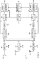
- Fig. 2 is a block diagram that schematically illustrates an interference-canceling receiver 58, in accordance with an embodiment of the present invention.
- the configuration of receiver 58 can be used for implementing receiver 36 of Fig. 1 above.
- receiver 58 comprises three receive antennas 60A...60C.
- Antenna 60A comprises a directional dish antenna that is pointed toward satellite 32. Nevertheless, antenna 60A receives the interfering signal in addition to the desired signal, e.g., via a side-lobe or back-lobe.
- Antennas 60B and 60C which may be directional or omnidirectional, receive the interfering signal and possibly the desired signal.
- the RX front end comprises three Low Noise Blocks (LNBs)/tuners 64A...64C that are connected to antennas 60A...60C.
- LNBs Low Noise Blocks
- Each LNB/tuner processes the RF signal received by its respective antenna.
- a given LNB/tuner amplifies the received signal and converts the signal from RF to IF while filtering the desired RF channel.
- the outputs of LNB/tuners 64A...64C are denoted y 1... y 3, respectively.
- each LNB/tuner can be activated or deactivated using an on/off interface, in order to train subsequent receiver elements (e.g., Automatic Gain Control - AGC) for each received signal separately.
- AWGN Additive Gaussian White Noise
- the desired signal receiver comprises a gain combining module 68A, a Band Pass Filter (BPF) 72A, a down-converter 76A and a demodulator 80A.
- the interfering signal receiver comprises a gain combining module 68B, a BPF 72B, a down-converter 76B and a demodulator 80B.
- Each gain combining module combines the outputs of LNB/tuners 64A...64C with respective weight coefficients.
- modules 68A and 68B perform analog gain combining. Alternatively, however, digital gain combining following sampling of the signals can also be used.
- Gain combining modules 68A and 68B are controlled by demodulators 80A and 80B, respectively.
- the demodulators calculate the weight coefficients G ji .
- Example techniques for calculating the weight coefficients are described further below.
- the output of gain combining module 68A ( ⁇ 1 ) is filtered by a Band Pass Filter (BPF) 72A, which removes out-of-band signal components.
- BPF Band Pass Filter
- the pass-band of BPF 72A typically corresponds to the bandwidth of a single satellite transponder.
- the BPS may filter out a portion of the interfering signal.
- a down-converter 76A down-converts the output of BPF 72A to baseband.
- a demodulator 80A decodes and reconstructs the desired signal.
- the output of gain combining module 68B ( ⁇ 2 ) is filtered by a BPF 72B.
- a down-converter 76B down-converts the output of BPF 72B to baseband.
- a demodulator 80B decodes and reconstructs the interfering signal.
- Interference-canceling receiver 58 comprises an interference generation unit 88, which exchanges signals and associated information between demodulators 80A and 80B in order to perform interference cancellation.
- demodulator 80B provides unit 88 with a version of the interfering signal that is extracted from some point along the reception path of demodulator 80B, as will be explained below.
- each demodulator (80A and 80B) provides unit 88 with frequency and timing information regarding its signal (e.g., residual frequency offset and timing estimate).
- Unit 88 uses the timing and frequency information to generate a version of the interfering signal, which is synchronized in time and frequency with the desired signal that is reproduced by demodulator 80A.
- Unit 88 provides this synchronized version of the interfering signal to demodulator 80A, which in turn subtracts it from the desired signal (or otherwise combines it with the desired signal).
- demodulator 80A of the desired signal has signal cancellation functionality for subtracting the interfering signal from the desired signal.
- both demodulators 80A and 80B have signal cancellation functionality, and the two demodulators carry out a successive decoding process that iteratively refines the decoded signals.
- demodulator 80A provides unit 88 with a version of the desired signal that is extracted from some point in the reception path (in addition to demodulator 80B providing a version of the interfering signal). Both demodulators provide unit 88 with timing and frequency information regarding their respective signals.
- unit 88 uses this information to generate a version of the desired signal that is synchronized (matched) in time and frequency with the interfering signal reproduced by demodulator 80B.
- Unit 88 provides the synchronized version of the desired signal to demodulator 80B, and demodulator 80B subtracts this signal from the interfering signal. As a result, the interfering signal is reproduced by demodulator 80B with improved accuracy.
- the successive decoding process performed by demodulators 80A and 80B and unit 88 may proceed iteratively for any suitable number of iterations. In each iteration, the signal reproduced by one demodulator is refined using the signal reproduced by the other demodulator. The process may initiate either with reproducing the desired signal first, or with reproducing the interfering signal first.
- the initial iteration is performed by the demodulator exhibiting the higher effective Signal to Noise Ratio (SNR), after gain combining by modules 68A and 68B, and while regarding the interference from the other signal as additional noise.
- the initial iteration is performed by the demodulator exhibiting the lower Bit Error Rate (BER), after gain combining and while regarding the interference from the other signal as additional noise, and while taking into account the modulation and code rate used by both demodulators.
- the demodulator for performing the initial iteration can be selected arbitrarily, or using any other suitable criterion. As seen from the above example, the decoding order may be fixed, or it may vary from one decoding session to another.
- any suitable termination criterion can be used for terminating the successive interference canceling process.
- the process continues for a predefined number of iterations.
- the process is terminated when the quality of the reconstructed desired signal meets a certain target quality. For example, the process may be terminated when the Error Vector Magnitude (EVM) or the BER of the desired signal is below a certain threshold.
- EVM Error Vector Magnitude
- the desired signal receiver and the interfering signal receiver are synchronized in time and frequency to a common reference.
- This synchronization causes the timing and frequency information (e.g., residual frequency offset and timing estimate) reported by demodulators 80A and 80B to remain valid over a long time period.
- the signals generated by interference regeneration unit 88 will also remain valid for a long time period, and the signal cancellation performed by demodulator 80A (and in some embodiments also by demodulator 80B) will be accurate.
- interference-canceling receiver 58 comprises a reference unit 84 that synchronizes the two receivers in time and frequency. This synchronization means that the relative carrier offsets and the timing clock frequency are synchronized in the two receivers.
- unit 84 generates clock and reset signals for down-converters 76A and 76B, demodulators 80A and 80B and interference regeneration unit 88. The clock and reset signals provided to all these modules are synchronized to the same reference clock.
- all the Local Oscillator (LO) signals and the Analog-to-Digital Converter (ADC) sampling clocks in receiver 58 are synchronized to the same reference clock. In other words, all frequency conversion operations and sampling operations in receiver 58 are synchronized to the same reference clock.
- receivers 52 and 56 also have a common timing reference.
- the desired signal and the interfering signal originate from different transmitters, which are not synchronized with one another in any way and typically have different air interfaces.
- offsets between the carrier frequencies and timing clock frequencies of the two signals should be estimated and compensated for.
- these estimations are carried out in the desired signal receiver and the interfering signal receiver, and unit 88 cancels the interference using the receiver estimates without adding dedicated estimation or synchronization mechanisms.
- Unit 88 is able to use the receiver estimates since the receivers are synchronized to one another by unit 84.
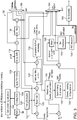
- Fig. 3 is a block diagram that schematically illustrates a demodulator 92 in an interference-canceling receiver, in accordance with an embodiment of the present invention.
- the configuration of demodulator 92 can be used, for example, for implementing demodulator 80A or 80B of Fig. 2 above.
- the reception path in demodulator 92 begins with an ADC 96, which accepts an analog baseband signal and samples the analog signal to produce a digital baseband signal.
- An analog AGC module 100 controls the signal gain.
- a gain combining calculation module 104 calculates the weight coefficients G ji that are applied by the respective gain combining module (module 68A or 68B in Fig. 2 above). The weight coefficient calculation may be based, for example, on soft signal values at the input to a slicer that makes bit decisions (see below), on hard bit values at the slicer output, on EVM measured at the slicer, on an estimate signal phase, on an estimated signal gain, and/or on any other suitable parameter.
- interference-canceling demodulator 92 calculates the weight coefficients using a Maximum Ratio Combining (MRC) process.
- demodulator 92 carries out the following MRC process: In the receiver that performs the initial decoding iteration, without interference cancellation:
- the above-described MRC process can be carried out using real (as opposed to complex) gain, and without the phase rotation.
- the weight coefficient of each receive antenna can be set proportionally to the power of the signal received by that antenna.
- the weight coefficients can be set using Equal Gain Combining (EGC), in which the amplitudes of all weight coefficients are equal, and the weight coefficients compensate for phase rotation only.
- demodulator 92 may calculate and set weight coefficients G ji using any other suitable technique.
- a digital front end 108 decimates the signal, to produce a baseband signal having a lower sampling rate. Decimation may be performed in a single stage or in multiple successive stages. Each decimation stage typically performs both filtering and decimation of the signal. Filtering is important to prevent aliasing.
- the signal produced by digital front end 108 is delayed using a delay buffer 112. Buffer 112 is typically disabled (e.g., bypassed) in the receiver that performs the initial decoding iteration, and is activated in the other receiver. The delay of buffer 112 provides sufficient time for the first receiver and the interference regeneration to generate the interference signal for cancellation.
- the output of delay buffer 112 is filtered by an Adjacent Channel Interference (ACI) filter 116.
- the ACI filter typically filters-out neighboring channels.
- a resampler 120 resamples the signal at the output of ACI filter 116.
- the resampler resamples the signal at optimal sampling rate and times, as indicated by a timing estimation module 124.
- Module 124 estimates the optimal sampling times within the symbols in the signal, in order to optimize the resulting receiver performance (e.g., to minimize EVM at the slicer input).
- module 124 initializes the timing estimation according to an initial timing estimation obtained from an acquisition module 132, described further below.
- the timing estimation may train, for example, based on slicer errors calculated on data symbols, slicer errors calculated on pilot symbols, correlation between the received samples and a known training sequence, slicer decisions (e.g., using Mueller-Muller timing loop), received samples (blind estimation, such as using a Gardner timing loop), phase slope along bins in case of OFDM modulation, or based on any other suitable parameters.
- residual timing correction may be corrected in the frequency domain following a subsequent FFT module - described below.
- module 124 provides the estimated timing frequency offset (clock frequency offset), denoted T f , as output. This output is provided to interference regeneration unit 88 for use in the interference cancellation process, as described above.
- the signal is processed by a matched filter or Fast Fourier Transform (FFT) module 128.
- FFT Fast Fourier Transform
- a matched filter is typically used for single-carrier modulation.
- An FFT is typically used for OFDM or OFDMA modulation.
- the output of module 128 comprises a sequence of reconstructed constellation symbols. The reconstructed symbols are provided to the subsequent modules along the reception path, and to an acquisition and pilot processing module 132.
- Module 132 typically estimates the initial frequency offset of the received symbols.
- the estimation may be performed, for example, once per a transmission burst (when the air interface defines transmission in bursts), once per frame or during first startup (for a continuous transmission air interface such as DVB-S2), or whenever data (e.g., pilot symbols) is available for training.
- the estimation process may involve, for example, signal auto-correction, cross-correction with expected training data, channel and gain estimation according to expected training data, frequency estimation according to phase estimation at different locations, estimation of phase slope and rotation of OFDM bins, estimation of amplitude distortion of known OFDM bins, and/or any other suitable estimation technique.
- phase/frequency tracking & correction module 136 is initialized by the frequency and phase estimation obtained from acquisition module 132 and then applied to the reconstructed symbols. Module 136 then continues to track the phase/frequency of the reconstructed symbols in order to fix residual phase/frequency errors, possible Doppler effects and phase noise. Training of phase/frequency tracking may be based, for example, on slicer errors according to slicer decisions, or on known pilot symbols.
- module 136 provides the estimated frequency error, denoted C f , as output. This output is provided to interference regeneration unit 88 for use in the interference cancellation process, as described above.
- gain tracking and correction in module 140 is initialized by gain estimation that is obtained from acquisition module 132, and then applied to the reconstructed symbols. Module 140 then continues to track the gain of the reconstructed symbols in order to fix residual gain errors. Training of gain tracking may be based, for example, on slicer errors according to slicer decisions, or on known pilot symbols.
- channel tracking and equalization in module 144 may be initialized by a channel estimation obtained from acquisition module 132, and then applied to the reconstructed symbols. Module 144 then continues to track the channel response on the reconstructed symbols, in order to fix residual errors and channel variations. Training of channel tracking may be based, for example, on slicer errors according to slicer decisions, or on known pilot symbols.
- Equalization in module 144 may be carried out, for example, using a time-domain equalizer such as a symbol-spaced equalizer, a fractionally-spaced equalizer, a Feed Forward Equalizer (FFE), a Decision Feedback Equalizer (DFE), a Maximum Likelihood Sequence Estimator (MLSE) or a sub-optimal MLSE.
- the time-domain equalizer may comprise real or complex tap coefficients.
- equalization in module 144 may be performed using a frequency-domain equalizer such as a single-tap-per-bin equalizer, an equalizer having multiple taps per bin, using coefficient smoothing in the time domain, using coefficient smoothing in the frequency domain, or using any other suitable equalizer.
- the equalizer in module 144 When the equalizer in module 144 is implemented in the time domain, its main tap may be set to unity. In this embodiment, the phase rotation and gain correction are typically performed separately. When the main equalizer tap is complex, the equalizer and equalizer training may also perform phase and gain corrections. When equalization is performed in the frequency domain, the equalizer typically also performs the phase correction, and therefore separate phase estimation is not required. The equalizer may also perform gain correction instead of module 140.
- the signal is provided to a slicer 148.
- the slicer accepts as input soft symbols, and outputs respective hard symbols according to the symbol constellation of the modulation scheme used by the receiver.
- slicer 148 also outputs the slicer errors, i.e., the difference between the respective slicer output (hard) and input (soft) symbols. Additionally or alternatively, the slicer also calculates and outputs an estimate of the EVM.
- the symbols at the slicer output are de-interleaved by a de-interleaver 152, which reorders the data.
- the de-interleaver typically reverses the operation of an interleaver in the transmitter.
- the de-interleaver may operate on bits, symbols or any other soft data, such as Log Likelihood Ratios (LLR).
- LLR Log Likelihood Ratios
- the de-interleaver may comprise, for example, a block or convolution de-interleaver.
- a Forward Error Correction (FEC) decoder 156 decodes a FEC code that is used by the transmitter to encode the data.
- the FEC decoder thus outputs a sequence of bits that estimate the data bits encoded by the transmitter.
- the FEC decoder may comprise, for example, a soft-input or hard-input decoder.
- the FEC code may comprise any suitable code, such as, for example, a Low Density Parity Check (LDPC) code, a Reed Solomon (RS) code, a convolutional code, a Turbo code, a Bose-Chaudhuri-Hocquenghem (BCH) code, a combination of such codes, or any other suitable FEC code.
- LDPC Low Density Parity Check
- RS Reed Solomon
- BCH Bose-Chaudhuri-Hocquenghem
- a de-scrambling module 160 applies a de-scrambling operation to the decoded bits.
- demodulator 92 outputs an additional output denoted SigOut (in addition to the reconstructed signal produced by module 160).
- Output SigOut is provided to interference regeneration unit 88 for interference cancellation purposes, i.e., for subtraction from the signal received by the other demodulator.
- unit 88 converts this signal into a signal that is matched in time and frequency to the received signal of the other receiver, in order to enable accurate interference cancellation.
- this functionality is supported in both the desired signal receiver and the interfering signal receiver.
- this functionality is supported only in the interfering signal receiver.
- demodulator 92 can be configured to extract SigOut from various points along the reception path.
- the selected SigOut may comprise, for example, a baseband signal (a sequence of baseband samples) or decoded bits, depending on the selected extraction point.
- demodulator 92 comprises a multiplexer 164, which selects the desired output SigOut in response to a control signal denoted sel2.
- Possible extraction points of the output SigOut may comprise, for example, the output of the Delay Buffer 112, the output of ACI filter 116 (after removal of irrelevant out-of-band signal components), the output of resampler 120 (so as to provide an output signal that is sampled at the correct timing), the soft symbols at the input of slicer 148, the soft symbols as estimated by FEC decoder 156, or the decoded bits produced FEC decoder 156.
- selection of the desired extraction point of SigOut is performed during initialization or factory setting.
- the desired SigOut may be selected and modified automatically during operation, e.g., by the interference regeneration unit, based on any suitable criterion.
- demodulator 92 accepts an estimate of the signal received by the other receiver (denoted "Estimated Interference” in the figure), and subtracts this signal from the received signal in order to perform interference cancellation.
- Estimated Interference In interference-canceling receivers that perform successive decoding, this functionality is supported in both the desired signal receiver and the interfering signal receiver. In interference-canceling receivers that do not perform successive decoding, this functionality is supported only in the desired signal receiver.
- demodulator 92 can be configured to subtract the estimated interference at various subtraction points along the reception path.
- demodulator 92 comprises a multiplexer 168, which selects the desired subtraction point in response to a control signal denoted sel1.
- Possible subtraction points may comprise, for example, the output of Delay Buffer 112, the output of ACI filter 116, the output of resampler 120, the output of matched filter/FFT module 128, or the input of slicer 148 (after equalization by module 144).
- selection of the desired interference subtraction point is performed during initialization or factory setting.
- the desired subtraction point may be selected and modified automatically during operation, e.g., by the interference regeneration unit, based on any suitable criterion.
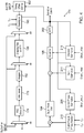
- Fig. 4 is a block diagram that schematically illustrates an interference regeneration unit 170, in accordance with an embodiment of the present invention.
- the configuration of unit 170 may be used, for example, for implementing unit 88 of Fig. 2 above,
- Unit 170 accepts an input signal from one of the demodulators (e.g., signal SigOut from a demodulator 92 as shown in Fig. 3 ), converts the signal into a version that is matched in time and frequency to the signal received by the other demodulator (e.g., another demodulator 92 as shown in Fig. 3 ), and provides the signal to the other demodulator (e.g., as the "Estimated Interference" input to demodulator 92 in Fig. 3 ) for performing interference cancellation.
- the demodulators e.g., signal SigOut from a demodulator 92 as shown in Fig. 3
- the other demodulator e.g., another demodulator 92 as shown in Fig. 3
- the other demodulator e.g., as the "Estimated Interference" input to demodulator 92 in Fig. 3
- the input to unit 170 is denoted SigOut1 or SigOut2, depending on whether it originates from the demodulator of the desired signal or from the demodulator of the interfering signal.
- the output of unit 170 is denoted Estint1 or Estint2, depending on whether it is destined to the demodulator of the interfering signal or from the demodulator of the desired signal.
- Unit 170 comprises a signal generation path, which comprises a FEC encoder 174, an interleaver 178, a mapper 182, a shaping filter or Inverse FFT (IFFT) module 186, a resampler 190, a digital front end 194, an equalizer 198 and a BPF 202.
- unit 170 can be configured to accept the signal SigOut at various points along the signal generation path, using a control signal denoted sel.
- SigOut can be injected either at the input of FEC decoder 174, at the input of shaping filter/IFFT module 186, or at the input of resampler 190. The choice of injection point typically depends on the extraction point from which SigOut was extracted in the first demodulator.
- unit 170 can be configured to output the signal Estint from various points along the signal generation path, using logic that is not shown in this figure. The choice of extraction point of Estint typically depends on the point at which Estint is to be subtracted in the second demodulator.
- the various elements of unit e.g., resampler 190, rotator 210 and front-end 194 can be configured to let the signal pass through them without processing, i.e., to self-bypass.
- the signal at the output of unit 170 can be configured for insertion (subtraction) at any desired point in the second demodulator.
- SigOut comprises decoded bits, it is typically provided to FEC encoder 174. If SigOut comprises soft or hard symbols, it is typically provided to shaping-filter/IFFT (Inverse FFT) module 186. If SigOut comprises samples extracted before the matched filter/FFT, it is typically provided to resampler 190.
- FEC encoder 174 If SigOut comprises soft or hard symbols, it is typically provided to shaping-filter/IFFT (Inverse FFT) module 186. If SigOut comprises samples extracted before the matched filter/FFT, it is typically provided to resampler 190.
- IFFT Inverse FFT
- interference regeneration unit 170 accepts a frequency error and a timing-clock estimate from each demodulator (i.e., from the demodulator of the desired signal and from the demodulator of the interfering signal), as well as a common clock and reset signal from the common reference unit (e.g., reference unit 84 of Fig. 2 ). Based on these inputs, the interference regeneration unit aligns the frequency and timing of signal EstInt so as to match the frequency and timing of the signal received in the second receiver (i.e., the signal from which EstInt is to be subtracted).
- the alignment may comprise relative timing-clock alignment according to the timing-clock estimates from both receivers, relative frequency offset according to the frequency error estimations from both receivers, relative phase offset, relative timing offset, relative gain and/or relative channel response (relative Inter-Symbol Interference - ISI).
- unit 170 chooses between SigOut1 and SigOut2 as the input signal (i.e., chooses whether to take the input signal from the first or the second receiver) and generates an estimated interference signal EstInt that is provided to the other receiver.
- FEC encoder 174 encodes the data bits with a FEC, to produce encoded bits.
- Interleaver 178 reorders the data. Interleaver 178 may operate on bits or on symbols. If operating on symbols, the interleaver is typically placed after mapper 182, and not before the mapper as shown in Fig. 4 .
- Mapper 182 converts the bits into symbols according to the constellation of the modulation type used.
- Module 186 applies pulse shaping or IFFT. Pulse shaping is typically applied when using single-carrier modulation. In these embodiments, module 186 shapes the symbols according to the pulse shape of the applicable air interface (e.g., a squared root raised cosine pulse according to the DVB-S2 standard). In some embodiments, module 186 also interpolates the shaped signal. Module 186 typically applies IFFT when using OFDM or OFDMA. In these embodiments, module 186 converts the symbols from the frequency domain to the time domain, and possibly also interpolates the converted signal.
- Pulse shaping is typically applied when using single-carrier modulation. In these embodiments, module 186 shapes the symbols according to the pulse shape of the applicable air interface (e.g., a squared root raised cosine pulse according to the DVB-S2 standard). In some embodiments, module 186 also interpolates the shaped signal. Module 186 typically applies IFFT when using
- Resampler 190 accepts the timing-clock estimates from the first and second receivers (e.g., Tf in Fig. 3 , denoted T f1 and T f 2 in Fig. 4 ). Resampler 190 is also controlled by the same reference clock as the first and second receivers. Based on the timing clock estimations, resampler 190 compensates for the relative different timing-clock rates of the desired signal and the interfering signal. This timing-clock offset is typically caused because the transmitters of the desired and interferer signals are not driven by the same clock and therefore are not aligned.
- Resampler 190 may also compensate for the relative latency between the two signals.
- resampler 190 may assume fixed and known delays between the SigOut extraction point in the first receiver and the location of interference cancellation (subtraction point) in the second receiver. Based on this information, the resampler determines at which sampling times to resample the input signal, and resamples the signal so as to correct the relative timing delay.
- Possible implementations of resampler 190 may comprise, for example, linear interpolation, cubic interpolation or interpolation using filter bank.
- a timing offset estimation module 192 adapts the signal latency, e.g., by correlating the Estint signal with the slicer input (Slicer_in) and finding the location of the correlation peak.
- unit 170 comprises a carrier phase estimation module 206 and a digital frequency & phase rotation module 210.
- Modules 206 and 210 adjust the phase and frequency of the regenerated signal in order to match it in phase and frequency to the signal received by the second demodulator.
- module 210 accepts the frequency error estimates from the first and second receivers (e.g., C f in Fig. 3 , denoted C f1 and C f2 in Fig. 4 ).
- Modules 206 and 210 are also controlled by the common reference clock as the other timing and frequency conversions (e.g., LO signals) in the receivers.
- Modules 206 and 210 are assumed to be aware of the nominal relative frequency offset between the center frequencies of the first and second receivers. Based on this information, modules 206 and 210 generate a complex carrier signal e j ⁇ fk + ⁇ p , which is subsequently used to multiply the signal in order to correct the relative frequency error.
- the relative phase rotation ⁇ p is calculated by phase estimation module 206.
- the phase estimation module trains in order to optimize ⁇ p so as to minimize the resulting EVM in the second receiver.
- the phase is typically updated at the first sample n after each time the slicer input and output are updated.
- the convergence factor ⁇ k may be constant, or it may vary (e.g., according to a predefined table) in order to accelerate convergence.
- digital front end module 194 converts the signal rate of the input signal SigOut to the required rate of the output signal EstInt.
- Module 194 may perform up-sampling or down-sampling, depending on the ratio between the input and output rates. Up-sampling or down-sampling may be performed in a single stage or in multiple stages in order to reduce implementation complexity.
- Gain estimation module 214 estimates and corrects the relative gain, denoted g, between the estimated interference signal and the gain of the second receiver.
- the gain estimation module typically trains in order to optimize g so as to minimize the resulting EVM in the second receiver.
- the gain correction may be real (as opposed to complex), since the signal phase is corrected separately by modules 206 and 210. Alternatively, the gain correction may be complex, in which case the phase estimation module may be omitted.
- the gain is typically updated at the first sample n after each time the slicer input and output are updated.
- the convergence factor ⁇ k may be constant, or it may vary (e.g., according to a predefined table) in order to accelerate convergence.
- Equalizer 198 typically comprises a time-domain filter, e.g., a Finite Impulse Response (FIR) or Infinite Impulse Response (IIR) filter.
- the filter typically trains in order to optimize the filter coefficients so as to minimize the resulting EVM in the second receiver.
- the filter coefficients may be real or complex.
- the filter may comprise a fixed main tap equal to unity, since gain correction and phase correction are performed separately by modules 206 and 214.
- the filter may comprise a complex main tap having a variable amplitude. In this embodiment, modules 206 and 214 may be omitted.
- the equalizer coefficients may be updated at the first n sample after each time the slicer input and output are updated. Alternatively, the equalizer coefficients may be updated at each n sample according to the last slicer input and output updates. Further alternatively, the equalizer coefficients may be updated at the first k sample after each time the delay line is updated. As another example, the equalizer coefficients may be updated at each k sample according to the last delay line update.
- the convergence factor ⁇ k may be constant, or it may vary (e.g., according to a predefined table) in order to accelerate convergence.
- the BPF 202 performs band-pass filtering that limits the signal that is provided to the second receiver to the frequency band of the desired signal.
- the BPF can be incorporated within equalizer 198.
- the BPF and equalizer are implemented separately in order to simplify the implementation of the equalizer.
- the interference re-generation module typically outputs a zero signal during time periods that are between bursts.
- receiver and interference regeneration module configurations described herein can be generalized to the case of multiple interfering signals that cause interference to a certain desired signal.
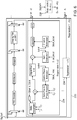
- Fig. 5 is a block diagram that schematically illustrates an interference-canceling receiver 220, in accordance with an alternative embodiment of the present invention.
- receiver 220 comprises three reception paths for receiving a desired satellite signal and two interfering signals.
- the reception paths are similar in structure and functionality to the reception paths shown in Fig. 2 above.
- Receiver 220 comprises a reference unit 224, which is similar to unit 84, but provides reference timing and clock signals to three reception paths instead of two.
- Receiver 220 comprises an interference regeneration unit 228, which is described in greater details below.
- the second interfering signal (denoted IntSig2 in the figure) is decoded first, the estimated second interfering signal is subtracted from the first interfering signal (denoted IntSig1 in the figure) and the first interfering signal is decoded. Then, the estimates of the first and second interfering signals are subtracted from the desired (satellite) signal and the satellite signal is decoded. Alternatively, any other suitable decoding order can also be used.
- Another alternative is to decode the first and second interfering signals first, each interfering signal decoded separately without successive interference cancellation, and then to remove both interfering signals from the desired signal path.
- successive interference cancellation on the interfering signal paths is optional and not a must.
- a certain decoding order is set.
- the estimated interference from all the receivers that have been decoded so far is subtracted from all the signals yet to be decoded, with proper adjustments of the interference regeneration module.
- the order in which the interfering signals are decoded may be set according to any suitable criterion.
- the decoding order may be set arbitrarily, e.g., at random, based on the EVM at each receiver (e.g., receivers with better EVM are decoded first, or receivers with worse EVM are decoded first), based on the BER measure in each receiver (e.g., receivers with better BER are decoded first, or receivers with worse BER are decoded first), or according to any other suitable order.
- the desired (satellite) signal is typically decoded last.
- Fig. 6 is a block diagram that schematically illustrates an interference regeneration unit 230, which performs interference regeneration for N interfering signals, in accordance with an alternative embodiment of the present invention.
- Unit 230 accepts a SigOut signal from one of the N receivers, and generates interference estimation signals to the remaining N-1 receivers.
- some of the regeneration path is common to the N-1 signals, and some of the path is duplicated N -1 times using N-1 regeneration modules 234.
- Unit 230 accepts signal SigOut1 as input, and generates the interference cancellation signals for receivers 2,3,4... N. A similar unit should be used for generating the interference cancellation signals for receivers 1,3,4...N from SigOut2. In other words, unit 230 is duplicated N times. The N th duplicate is denoted 238 in the figure.
- Fig. 6 supports any decoding order i.e., interference cancellation from any receiver to any other receiver.
- a simplified configuration can be implemented by limiting the decoding order. For example, interference cancellation from the satellite receiver to other receivers can be omitted if the desired signal is decoded last.
- each demodulator may be similar to demodulator 92 of Fig. 3 above, with a slight modification that enables the demodulator to accept and subtract multiple interfering signal estimates.
- a demodulator may combine (e.g., sum) the interfering signal estimates, and then add the combined interfering signal into the reception path of the desired signal.
- the demodulator may comprise separate logic for each estimated interference signal, such that the demodulator is able to add each interfering signal at a different location.
- Figs. 1-6 The configurations of the receivers, demodulators and interference regeneration units shown in Figs. 1-6 above are example configurations which are chosen purely for the sake of conceptual clarity. In alternative embodiments, any other suitable configurations can also be used. For example, the partitioning of functions among the different elements may be modified in any suitable way. Some receiver elements that are not mandatory for understanding of the disclosed techniques, such as DC offset removal and I/Q mismatch correction elements, are omitted from the figured for the sake of clarity.
- receiver, demodulator and interference regeneration unit components described herein can be implemented in hardware, such as using one or more discrete components, Field-Programmable Gate Arrays (FPGAs), Application-Specific Integrated Circuits (ASICs) or Radio Frequency Integrated Circuits (RFICs).
- FPGAs Field-Programmable Gate Arrays
- ASICs Application-Specific Integrated Circuits
- RFICs Radio Frequency Integrated Circuits
- some receiver, demodulator and interference regeneration unit components can be implemented in software or using a combination of hardware and software elements.
- Fig. 7 is a flow chart that schematically illustrates a method for reception using interference cancellation, in accordance with an embodiment of the present invention.
- the method begins with a front end of an interference-canceling receiver (e.g., receiver 36, 58 or 220) receiving an RF channel that contains a desired signal and an interfering signal, at a reception step 240.
- an interference-canceling receiver e.g., receiver 36, 58 or 220
- the two receivers perform an acquisition phase in which each receiver estimates the timing clock offset and carrier frequency offset in each respective signal, at an acquisition step 242. This estimation is typically possible even before performing interference cancellation, for example since it is usually based on pilot signals that are resilient to interference.
- the two receivers are synchronized to a common frequency and timing reference.
- the interfering signal receiver decodes the interfering signal, at an interfering signal decoding step 244.
- An interference regeneration unit extracts the interfering signal from a certain point in the interfering signal receiver, and regenerates a version of this signal that is matched in time and frequency to the desired signal received by the desired signal receiver, at a regeneration step 248.
- the interference regeneration unit provides the regenerated signal to the desired signal receiver, and the desired signal receiver subtracts this signal from the desired signal.
- the desired signal receiver decodes the interference-free desired signal, at a desired signal decoding step 250, and provides the interference-free desired signal as output.
- WLAN Wireless Local Area Networks
- WiMAX WiMAX
- LTE Long Term Evolution
Landscapes
- Engineering & Computer Science (AREA)
- Computer Networks & Wireless Communication (AREA)
- Signal Processing (AREA)
- Noise Elimination (AREA)
Claims (15)
- Procédé pour une communication, comprenant :recevoir un canal radiofréquence (RF), qui contient un signal souhaité conforme à une première interface radio et un signal de brouillage conforme à une seconde interface radio qui est différente de la première interface radio, par un premier récepteur (52) qui est configuré pour la première interface radio et reçoit le canal RF par l'intermédiaire d'une première antenne (44), et par un second récepteur (56) qui est configuré pour la seconde interface radio et reçoit le canal RF par l'intermédiaire d'une seconde antenne (44) qui est différente de la première antenne ;synchroniser le premier récepteur (52) et le second récepteur (56) sur une référence de fréquence et de temporisation commune, bien que le premier récepteur (52) et le second récepteur (56) soient configurés pour des interfaces radio différentes ; ettandis que les premier et second récepteurs sont synchronisés, décoder le signal souhaité à partir du canal RF à l'aide du premier récepteur (52) pour générer une première sortie, décoder le signal de brouillage à partir du canal RF à l'aide du second récepteur (56) pour générer une seconde sortie, et reconstruire le signal souhaité tout en supprimant le signal de brouillage par traitement conjoint des première et seconde sorties.
- Procédé selon la revendication 1, dans lequel le traitement conjoint des première et seconde sorties comprend : traiter la seconde sortie de façon à générer une seconde sortie ajustée qui correspond à la première sortie en temps et en fréquence, et combiner la seconde sortie ajustée à la première sortie.
- Procédé selon la revendication 2, dans lequel le traitement de la seconde sortie comprend : accepter à partir des premier et second récepteurs des estimations de temporisation et de fréquence concernant le signal souhaité et le signal de brouillage, respectivement, et ajuster la seconde sortie sur la base des estimations de temporisation et de fréquence.
- Procédé selon la revendication 3, dans lequel le traitement conjoint des première et seconde sorties comprend en outre : traiter la première sortie de façon à générer une première sortie ajustée qui correspond à la seconde sortie en temps et en fréquence, et combiner la première sortie ajustée à la seconde sortie.
- Procédé selon la revendication 4, dans lequel le traitement conjoint des première et seconde sorties comprend : évaluer un critère de sélection afin de réaliser une sélection entre :un premier ordre, dans lequel la première sortie ajustée est initialement générée et combinée à la seconde sortie, puis la seconde sortie ajustée est générée et combinée à la première sortie ; etun second ordre, dans lequel la seconde sortie ajustée est initialement générée et combinée à la première sortie, puis la première sortie ajustée est générée et combinée à la seconde sortie.
- Procédé selon la revendication 4, dans lequel le traitement conjoint des première et seconde sorties comprend : alterner entre un ajustement de la première sortie et un ajustement de la seconde sortie jusqu'à la satisfaction d'un critère de fin.
- Procédé selon la revendication 1, dans lequel le décodage du signal souhaité comprend : produire une première somme pondérée de multiples copies du canal RF reçues par l'intermédiaire de multiples antennes respectives et fournir la première somme pondérée en tant qu'entrée au premier récepteur, et dans lequel le décodage du signal de brouillage comprend : produire une seconde somme pondérée des multiples copies du canal RF et fournir la seconde somme pondérée en tant qu'entrée au second récepteur.
- Procédé selon la revendication 1, dans lequel la reconstruction du signal souhaité comprend : extraire le signal de brouillage à partir d'un point d'extraction sélectionné parmi un groupe de points d'extraction dans le second récepteur, et éliminer le signal de brouillage extrait du signal souhaité au niveau d'un point d'annulation sélectionné parmi un ensemble de points d'annulation dans le premier récepteur.
- Procédé selon la revendication 1, dans lequel le signal souhaité est reçu en provenance d'un satellite (32), et dans lequel le signal de brouillage est reçu en provenance d'un système de communication terrestre (40).
- Procédé selon la revendication 1, dans lequel la réception du canal RF comprend : recevoir au moins deux signaux de brouillage en plus du signal souhaité, dans lequel le décodage du signal de brouillage comprend : décoder les au moins deux signaux de brouillage à l'aide d'au moins deux seconds récepteurs respectifs qui sont synchronisés sur la référence de fréquence et de temporisation commune, pour produire au moins deux secondes sorties, et dans lequel le traitement conjoint des première et seconde sorties comprend : reconstruire le signal souhaité tout en supprimant les au moins deux signaux de brouillage.
- Procédé selon la revendication 10, dans lequel le traitement conjoint des première et seconde sorties comprend : sélectionner un ordre parmi les secondes sorties sur la base d'un critère d'ordonnancement, et combiner les secondes sorties au signal souhaité selon l'ordre sélectionné.
- Appareil de communication (20), comprenant :une extrémité avant (48), qui est configurée pour recevoir un canal radiofréquence (RF) contenant un signal souhaité conforme à une première interface radio et un signal de brouillage conforme à une seconde interface radio qui est différente de la première interface radio ;une première antenne (44) ;une seconde antenne (44) qui est différente de la première antenne ;un premier récepteur (52), qui est configuré pour la première interface radio, configuré pour recevoir le canal RF par l'intermédiaire de la première antenne (44) et configuré pour reconstruire le signal souhaité à partir du canal RF par décodage de la première interface radio, pour produire une première sortie ;un second récepteur (56), qui est configuré pour la seconde interface radio, configuré pour recevoir le canal RF par l'intermédiaire de la seconde antenne (44) et configuré pour reconstruire le signal de brouillage à partir du canal RF par décodage de la seconde interface radio, pour produire une seconde sortie ;une unité de référence (84), qui est configurée pour synchroniser les premier et second récepteurs sur une référence de fréquence et de temporisation commune, bien que le premier récepteur (52) et le second récepteur (56) soient configurés pour des interfaces radio différentes ; etune unité de régénération de brouillage (88), qui est configurée pour fournir la seconde sortie au premier récepteur (52), et pour amener le premier récepteur (52) à reconstruire le signal souhaité tout en supprimant le signal de brouillage.
- Appareil selon la revendication 12, dans lequel l'unité de régénération de brouillage est configurée pour traiter la seconde sortie de façon à générer une seconde sortie ajustée qui correspond à la première sortie en temps et en fréquence, et dans lequel le premier récepteur est configuré pour combiner la seconde sortie ajustée à la première sortie.
- Appareil selon la revendication 12, comprenant en outre une première unité de combinaison de gain qui est configurée pour produire une première somme pondérée de multiples copies du canal RF reçues par l'intermédiaire de multiples antennes respectives et pour fournir la première somme pondérée en tant qu'entrée au premier récepteur, et une seconde unité de combinaison de gain qui est configurée pour produire une seconde somme pondérée des multiples copies du canal RF et pour fournir la seconde somme pondérée en tant qu'entrée au second récepteur.
- Appareil selon la revendication 12, dans lequel le second récepteur et l'unité de régénération de brouillage sont configurés pour extraire le signal de brouillage à partir d'un point d'extraction sélectionné parmi un groupe de points d'extraction dans le second récepteur, et dans lequel le premier récepteur et l'unité de régénération de brouillage sont configurés pour éliminer le signal de brouillage extrait du signal souhaité au niveau d'un point d'annulation sélectionné parmi un ensemble de points d'annulation dans le premier récepteur.
Applications Claiming Priority (2)
| Application Number | Priority Date | Filing Date | Title |
|---|---|---|---|
| US13/031,216 US8644866B2 (en) | 2011-02-20 | 2011-02-20 | Satellite receiver with interfering signal cancellation |
| PCT/IB2012/050622 WO2012110930A2 (fr) | 2011-02-20 | 2012-02-12 | Récepteur de satellite à annulation de signal brouilleur |
Publications (3)
| Publication Number | Publication Date |
|---|---|
| EP2676377A2 EP2676377A2 (fr) | 2013-12-25 |
| EP2676377A4 EP2676377A4 (fr) | 2016-02-10 |
| EP2676377B1 true EP2676377B1 (fr) | 2019-07-24 |
Family
ID=46653169
Family Applications (1)
| Application Number | Title | Priority Date | Filing Date |
|---|---|---|---|
| EP12747383.3A Active EP2676377B1 (fr) | 2011-02-20 | 2012-02-12 | Récepteur de satellite à annulation de signal brouilleur |
Country Status (3)
| Country | Link |
|---|---|
| US (1) | US8644866B2 (fr) |
| EP (1) | EP2676377B1 (fr) |
| WO (1) | WO2012110930A2 (fr) |
Families Citing this family (37)
| Publication number | Priority date | Publication date | Assignee | Title |
|---|---|---|---|---|
| US8045660B1 (en) | 2007-05-23 | 2011-10-25 | Hypres, Inc. | Wideband digital spectrometer |
| US8249540B1 (en) | 2008-08-07 | 2012-08-21 | Hypres, Inc. | Two stage radio frequency interference cancellation system and method |
| US9401784B2 (en) * | 2009-10-21 | 2016-07-26 | Qualcomm Incorporated | Time and frequency acquisition and tracking for OFDMA wireless systems |
| US10111111B2 (en) | 2009-11-19 | 2018-10-23 | Qualcomm Incorporated | Per-cell timing and/or frequency acquisition and their use on channel estimation in wireless networks |
| US8792598B1 (en) * | 2011-08-02 | 2014-07-29 | Marvell International Ltd. | Coexistence of multiple communication technologies on a single device |
| US20130156139A1 (en) * | 2011-12-15 | 2013-06-20 | Samsung Electronics Co., Ltd. | Wireless communication system with interference filtering and method of operation thereof |
| US9106497B2 (en) * | 2012-08-28 | 2015-08-11 | Intel Corporation | Apparatus and method for improving OFDM receiver performance in the presence of narrowband interferers |
| US9647799B2 (en) * | 2012-10-16 | 2017-05-09 | Inphi Corporation | FEC coding identification |
| US9219631B2 (en) * | 2012-09-21 | 2015-12-22 | Kratos Integral Holdings, Llc | System and method for increasing spot beam satellite bandwidth |
| EP2920892A4 (fr) | 2012-11-15 | 2016-07-20 | Novelsat Ltd | Annulation d'écho dans des appareils émetteurs-récepteurs de communication |
| US9197285B2 (en) | 2012-12-20 | 2015-11-24 | Deere & Company | Methods and apparatus for ameliorating signal reception |
| CN103916148B (zh) * | 2013-01-05 | 2016-08-03 | 华为技术有限公司 | 一种自适应射频干扰抵消装置、方法、接收机及通信系统 |
| CN103309229A (zh) * | 2013-07-10 | 2013-09-18 | 中国人民解放军国防科学技术大学 | 一种基于拟合法的星地动态双向时间同步与测距联合算法 |
| US9900029B2 (en) | 2013-08-07 | 2018-02-20 | Qualcomm Incorporated | Intra-frequency and inter-RAT receiver |
| US9806827B2 (en) * | 2013-09-13 | 2017-10-31 | Samsung Electronics Co., Ltd. | Computing system with interference cancellation mechanism and method of operation thereof |
| EP3066878B1 (fr) * | 2013-11-10 | 2018-08-15 | Telefonaktiebolaget LM Ericsson (publ) | Synchronisation de fréquence de liaison radio et temporelle pour petites cellules |
| US9548776B2 (en) * | 2014-01-16 | 2017-01-17 | Qualcomm Incorporated | Interference cancelation using cooperative sensing |
| EP3097673B1 (fr) * | 2014-01-23 | 2017-09-13 | Kratos Integral Holdings, LLC. | Système et procédé permettant d'augmenter la largeur de bande d'un satellite à faisceau étroit |
| US9444505B2 (en) * | 2014-04-11 | 2016-09-13 | Broadcom Corporation | System and method for frequency reuse for wireless point-to-point backhaul |
| KR102207829B1 (ko) * | 2014-05-19 | 2021-01-26 | 한국전자통신연구원 | 고효율 위성 서비스를 위한 통신 장치 및 방법 |
| US9438283B2 (en) * | 2014-05-23 | 2016-09-06 | Intel Corporation | Baseband time domain cancellation of data bus interference |
| CN104378823B (zh) * | 2014-12-06 | 2017-08-01 | 广东机电职业技术学院 | 一种单边同步双向测距方法 |
| US10148344B2 (en) | 2015-01-14 | 2018-12-04 | Novelsat Ltd. | Echo cancellation with transmitter-side pre-filtering |
| JP6214816B2 (ja) * | 2015-02-23 | 2017-10-18 | 三菱電機株式会社 | 受信装置 |
| CN106817704A (zh) * | 2015-11-27 | 2017-06-09 | 索尼公司 | 频谱接入方法以及使用该方法的设备 |
| US10230409B2 (en) * | 2016-05-24 | 2019-03-12 | Hughes Network Systems, Llc | Apparatus and method for reduced computation amplifier gain control |
| US9967021B2 (en) * | 2016-07-14 | 2018-05-08 | Suntrust Bank | Systems and methods for signal cancellation in satellite communication |
| KR102633143B1 (ko) * | 2016-12-23 | 2024-02-02 | 삼성전자주식회사 | 무선 채널 분류를 기초로 디지털 루프 필터 이득을 조절하는 자동 주파수 제어기, 상기 자동 주파수 제어기를 포함하는 무선 통신 장치, 자동 주파수 제어 방법 및 무선 통신 방법 |
| US10200071B1 (en) * | 2017-08-07 | 2019-02-05 | Kratos Integral Holdings, Llc | System and method for interference reduction in radio communications |
| CN116647240A (zh) * | 2018-12-17 | 2023-08-25 | 华为技术有限公司 | 一种用于载波聚合的射频接收机 |
| US11428806B2 (en) * | 2019-07-02 | 2022-08-30 | Eagle Technology, Llc | Communications system having interference mitigation for non-geostationary weather satellite and associated method |
| US11283476B2 (en) * | 2019-07-09 | 2022-03-22 | Raytheon Bbn Technologies Corp. | System and method for cancelling strong signals from combined weak and strong signals in communications systems |
| US11171696B2 (en) * | 2019-07-30 | 2021-11-09 | Nxp Usa, Inc. | Distributed MIMO long training field method and system |
| CN110519199A (zh) * | 2019-09-06 | 2019-11-29 | 重庆金美通信有限责任公司 | 一种基于sc-fdma宽带系统抗干扰方法 |
| US12250068B2 (en) | 2022-03-17 | 2025-03-11 | Integrasys LLC | System for aerial interferences cancellation and RF encryption and geolocation inhibition |
| WO2023225610A1 (fr) * | 2022-05-18 | 2023-11-23 | Wimbrow Steven Earl | Système, procédé, appareil et produit programme d'ordinateur pour fournir une annulation adaptative de bruit sans fil |
| US20250350348A1 (en) * | 2024-05-10 | 2025-11-13 | Kratos Integral Holdings Llc | Virtual network function for signal cancellation |
Family Cites Families (24)
| Publication number | Priority date | Publication date | Assignee | Title |
|---|---|---|---|---|
| US6975582B1 (en) * | 1995-07-12 | 2005-12-13 | Ericsson Inc. | Dual mode satellite/cellular terminal |
| US5596439A (en) | 1995-08-01 | 1997-01-21 | Viasat, Inc. | Self-interference cancellation for two-party relayed communication |
| US6144696A (en) * | 1997-12-31 | 2000-11-07 | At&T Corp. | Spread spectrum bit allocation algorithm |
| US6011952A (en) | 1998-01-20 | 2000-01-04 | Viasat, Inc. | Self-interference cancellation for relayed communication networks |
| US6597750B1 (en) | 1998-06-19 | 2003-07-22 | Thomson Licensing S.A. | Opposite polarization interference cancellation in satellite communication |
| US20020110206A1 (en) | 1998-11-12 | 2002-08-15 | Neal Becker | Combined interference cancellation with FEC decoding for high spectral efficiency satellite communications |
| US6675307B1 (en) | 2000-03-28 | 2004-01-06 | Juniper Networks, Inc. | Clock controller for controlling the switching to redundant clock signal without producing glitches by delaying the redundant clock signal to match a phase of primary clock signal |
| US6466958B1 (en) | 2000-09-12 | 2002-10-15 | Interstate Electronics Corporation, A Division Of L3 Communications Corporation | Parallel frequency searching in an acquisition correlator |
| US20020098802A1 (en) | 2000-12-12 | 2002-07-25 | Karabinis Peter D. | Mobile satellite communications systems, gateways and methods supporting multiple air interface standards |
| JP3427381B2 (ja) | 2001-06-20 | 2003-07-14 | 富士通株式会社 | 雑音キャンセル方法及び装置 |
| US6859641B2 (en) | 2001-06-21 | 2005-02-22 | Applied Signal Technology, Inc. | Adaptive canceller for frequency reuse systems |
| US6907093B2 (en) * | 2001-08-08 | 2005-06-14 | Viasat, Inc. | Method and apparatus for relayed communication using band-pass signals for self-interference cancellation |
| US7181161B2 (en) | 2001-09-14 | 2007-02-20 | Atc Technologies, Llc | Multi-band/multi-mode satellite radiotelephone communications systems and methods |
| US6725017B2 (en) | 2001-12-05 | 2004-04-20 | Viasat, Inc. | Multi-channel self-interference cancellation method and apparatus for relayed communication |
| US7006583B2 (en) | 2002-08-30 | 2006-02-28 | Intel Corporation | Method and apparatus for receiving differential ultra wideband signals |
| US20040042569A1 (en) | 2002-09-03 | 2004-03-04 | Electro-Radiation Incorporated | Method and apparatus to provide communication protection technology for satellite earth stations |
| US7492810B2 (en) | 2005-04-04 | 2009-02-17 | General Electric Company | Method and apparatus for segmented code correlation |
| US7761075B2 (en) * | 2005-09-21 | 2010-07-20 | Samsung Electronics Co., Ltd. | Apparatus and method for interference cancellation in wireless mobile stations operating concurrently on two or more air interfaces |
| WO2008066968A2 (fr) | 2006-06-30 | 2008-06-05 | Rf Magic, Inc. | Annulation d'interférence de satellite |
| US8290100B2 (en) * | 2006-08-08 | 2012-10-16 | Qualcomm Incorporated | Interference detection and mitigation |
| US7782935B1 (en) | 2006-08-31 | 2010-08-24 | Altera Corporation | Half-rate DFE with duplicate path for high data-rate operation |
| US8289837B2 (en) * | 2007-05-04 | 2012-10-16 | Qualcomm Incorporated | Methods and apparatuses for multimode Bluetooth and WLAN operation concurrently |
| US8085834B2 (en) * | 2008-04-30 | 2011-12-27 | Infineon Technologies Ag | System partitioning for multi-mobile devices |
| WO2010092225A1 (fr) * | 2009-02-16 | 2010-08-19 | Elektrobit System Test Oy | Procédé et appareil permettant de réaliser des estimations de signal |
-
2011
- 2011-02-20 US US13/031,216 patent/US8644866B2/en active Active
-
2012
- 2012-02-12 EP EP12747383.3A patent/EP2676377B1/fr active Active
- 2012-02-12 WO PCT/IB2012/050622 patent/WO2012110930A2/fr not_active Ceased
Non-Patent Citations (1)
| Title |
|---|
| None * |
Also Published As
| Publication number | Publication date |
|---|---|
| US20120214524A1 (en) | 2012-08-23 |
| US8644866B2 (en) | 2014-02-04 |
| WO2012110930A3 (fr) | 2012-11-01 |
| EP2676377A4 (fr) | 2016-02-10 |
| EP2676377A2 (fr) | 2013-12-25 |
| WO2012110930A2 (fr) | 2012-08-23 |
Similar Documents
| Publication | Publication Date | Title |
|---|---|---|
| EP2676377B1 (fr) | Récepteur de satellite à annulation de signal brouilleur | |
| US10148339B2 (en) | Communication system with channel compensating equalizer | |
| CN100388641C (zh) | 在传输信道之间确定增益偏置的方法 | |
| CA2597588C (fr) | Reception en diversite iterative | |
| CA2199760C (fr) | Systeme de radiodiffusion audionumerique | |
| KR100540171B1 (ko) | 지상파 디지털 텔레비젼 방송신호를 위한 동일채널중계장치 및 그 방법 | |
| US9742611B2 (en) | Synchronizing orthogonal frequency division multiplexed (OFDM) symbols in a receiver | |
| US10135518B2 (en) | Echo cancellation in communication transceivers | |
| US20080304589A1 (en) | Wireless receiver, method for controlling the wireless receiver, program for controlling the wireless receiver, and semiconductor integrated circuit | |
| US9461683B2 (en) | Communication receiver enhancements using multi-signal capture | |
| EP3172879A1 (fr) | Procédé de réception d'un signal numérique dans un système de communication numérique | |
| AU2006315620B2 (en) | Symbol tracking for AM in-band on-channel radio receivers | |
| US20130114649A1 (en) | Signal cancellation in a satellite communication system | |
| JP2021040313A (ja) | 受信信号の交差偏波を打ち消す無線通信受信器 | |
| CN113922868B (zh) | Dvb-rcs2 rl三涡轮迭代接收机及接收方法 | |
| JP6806497B2 (ja) | 偏波共用コンバータ、受信機及び衛星受信装置 | |
| Fines et al. | Fully digital M-ary PSK and M-ary QAM demodulators for land mobile satellite communications | |
| Liu et al. | Design and verification of high-order qam transceiver systems for mmwave sdrs under large delay multipath and high frequency offset effects | |
| Schwarzenbarth et al. | MMSE based interference processing for satellite broadcast reception | |
| JP2025130618A (ja) | 無線通信システム | |
| Hsiao et al. | A DSSS receiver for dual-mode DSSS/OFDM wireless LAN systems | |
| Grinewitschus et al. | Channel Estimation for a Multi-User System with Iterative Interference Cancelation |
Legal Events
| Date | Code | Title | Description |
|---|---|---|---|
| PUAI | Public reference made under article 153(3) epc to a published international application that has entered the european phase |
Free format text: ORIGINAL CODE: 0009012 |
|
| 17P | Request for examination filed |
Effective date: 20130910 |
|
| AK | Designated contracting states |
Kind code of ref document: A2 Designated state(s): AL AT BE BG CH CY CZ DE DK EE ES FI FR GB GR HR HU IE IS IT LI LT LU LV MC MK MT NL NO PL PT RO RS SE SI SK SM TR |
|
| DAX | Request for extension of the european patent (deleted) | ||
| A4 | Supplementary search report drawn up and despatched |
Effective date: 20160112 |
|
| RIC1 | Information provided on ipc code assigned before grant |
Ipc: H04B 1/12 20060101ALI20160105BHEP Ipc: H04B 7/08 20060101ALI20160105BHEP Ipc: H04B 7/00 20060101AFI20160105BHEP Ipc: H04B 1/10 20060101ALI20160105BHEP |
|
| RIC1 | Information provided on ipc code assigned before grant |
Ipc: H04B 1/12 20060101ALI20181221BHEP Ipc: H04B 1/10 20060101ALI20181221BHEP Ipc: H04B 7/00 20060101AFI20181221BHEP Ipc: H04B 7/08 20060101ALI20181221BHEP |
|
| GRAP | Despatch of communication of intention to grant a patent |
Free format text: ORIGINAL CODE: EPIDOSNIGR1 |
|
| STAA | Information on the status of an ep patent application or granted ep patent |
Free format text: STATUS: GRANT OF PATENT IS INTENDED |
|
| INTG | Intention to grant announced |
Effective date: 20190301 |
|
| GRAS | Grant fee paid |
Free format text: ORIGINAL CODE: EPIDOSNIGR3 |
|
| GRAA | (expected) grant |
Free format text: ORIGINAL CODE: 0009210 |
|
| STAA | Information on the status of an ep patent application or granted ep patent |
Free format text: STATUS: THE PATENT HAS BEEN GRANTED |
|
| AK | Designated contracting states |
Kind code of ref document: B1 Designated state(s): AL AT BE BG CH CY CZ DE DK EE ES FI FR GB GR HR HU IE IS IT LI LT LU LV MC MK MT NL NO PL PT RO RS SE SI SK SM TR |
|
| REG | Reference to a national code |
Ref country code: GB Ref legal event code: FG4D |
|
| REG | Reference to a national code |
Ref country code: CH Ref legal event code: EP |
|
| REG | Reference to a national code |
Ref country code: DE Ref legal event code: R096 Ref document number: 602012062260 Country of ref document: DE |
|
| REG | Reference to a national code |
Ref country code: AT Ref legal event code: REF Ref document number: 1159447 Country of ref document: AT Kind code of ref document: T Effective date: 20190815 |
|
| REG | Reference to a national code |
Ref country code: IE Ref legal event code: FG4D |
|
| REG | Reference to a national code |
Ref country code: NL Ref legal event code: MP Effective date: 20190724 |
|
| REG | Reference to a national code |
Ref country code: LT Ref legal event code: MG4D |
|
| REG | Reference to a national code |
Ref country code: AT Ref legal event code: MK05 Ref document number: 1159447 Country of ref document: AT Kind code of ref document: T Effective date: 20190724 |
|
| PG25 | Lapsed in a contracting state [announced via postgrant information from national office to epo] |
Ref country code: FI Free format text: LAPSE BECAUSE OF FAILURE TO SUBMIT A TRANSLATION OF THE DESCRIPTION OR TO PAY THE FEE WITHIN THE PRESCRIBED TIME-LIMIT Effective date: 20190724 Ref country code: AT Free format text: LAPSE BECAUSE OF FAILURE TO SUBMIT A TRANSLATION OF THE DESCRIPTION OR TO PAY THE FEE WITHIN THE PRESCRIBED TIME-LIMIT Effective date: 20190724 Ref country code: NO Free format text: LAPSE BECAUSE OF FAILURE TO SUBMIT A TRANSLATION OF THE DESCRIPTION OR TO PAY THE FEE WITHIN THE PRESCRIBED TIME-LIMIT Effective date: 20191024 Ref country code: BG Free format text: LAPSE BECAUSE OF FAILURE TO SUBMIT A TRANSLATION OF THE DESCRIPTION OR TO PAY THE FEE WITHIN THE PRESCRIBED TIME-LIMIT Effective date: 20191024 Ref country code: SE Free format text: LAPSE BECAUSE OF FAILURE TO SUBMIT A TRANSLATION OF THE DESCRIPTION OR TO PAY THE FEE WITHIN THE PRESCRIBED TIME-LIMIT Effective date: 20190724 Ref country code: NL Free format text: LAPSE BECAUSE OF FAILURE TO SUBMIT A TRANSLATION OF THE DESCRIPTION OR TO PAY THE FEE WITHIN THE PRESCRIBED TIME-LIMIT Effective date: 20190724 Ref country code: PT Free format text: LAPSE BECAUSE OF FAILURE TO SUBMIT A TRANSLATION OF THE DESCRIPTION OR TO PAY THE FEE WITHIN THE PRESCRIBED TIME-LIMIT Effective date: 20191125 Ref country code: LT Free format text: LAPSE BECAUSE OF FAILURE TO SUBMIT A TRANSLATION OF THE DESCRIPTION OR TO PAY THE FEE WITHIN THE PRESCRIBED TIME-LIMIT Effective date: 20190724 Ref country code: HR Free format text: LAPSE BECAUSE OF FAILURE TO SUBMIT A TRANSLATION OF THE DESCRIPTION OR TO PAY THE FEE WITHIN THE PRESCRIBED TIME-LIMIT Effective date: 20190724 |
|
| PG25 | Lapsed in a contracting state [announced via postgrant information from national office to epo] |
Ref country code: IS Free format text: LAPSE BECAUSE OF FAILURE TO SUBMIT A TRANSLATION OF THE DESCRIPTION OR TO PAY THE FEE WITHIN THE PRESCRIBED TIME-LIMIT Effective date: 20191124 Ref country code: RS Free format text: LAPSE BECAUSE OF FAILURE TO SUBMIT A TRANSLATION OF THE DESCRIPTION OR TO PAY THE FEE WITHIN THE PRESCRIBED TIME-LIMIT Effective date: 20190724 Ref country code: GR Free format text: LAPSE BECAUSE OF FAILURE TO SUBMIT A TRANSLATION OF THE DESCRIPTION OR TO PAY THE FEE WITHIN THE PRESCRIBED TIME-LIMIT Effective date: 20191025 Ref country code: AL Free format text: LAPSE BECAUSE OF FAILURE TO SUBMIT A TRANSLATION OF THE DESCRIPTION OR TO PAY THE FEE WITHIN THE PRESCRIBED TIME-LIMIT Effective date: 20190724 Ref country code: LV Free format text: LAPSE BECAUSE OF FAILURE TO SUBMIT A TRANSLATION OF THE DESCRIPTION OR TO PAY THE FEE WITHIN THE PRESCRIBED TIME-LIMIT Effective date: 20190724 Ref country code: ES Free format text: LAPSE BECAUSE OF FAILURE TO SUBMIT A TRANSLATION OF THE DESCRIPTION OR TO PAY THE FEE WITHIN THE PRESCRIBED TIME-LIMIT Effective date: 20190724 |
|
| PG25 | Lapsed in a contracting state [announced via postgrant information from national office to epo] |
Ref country code: TR Free format text: LAPSE BECAUSE OF FAILURE TO SUBMIT A TRANSLATION OF THE DESCRIPTION OR TO PAY THE FEE WITHIN THE PRESCRIBED TIME-LIMIT Effective date: 20190724 |
|
| PG25 | Lapsed in a contracting state [announced via postgrant information from national office to epo] |
Ref country code: PL Free format text: LAPSE BECAUSE OF FAILURE TO SUBMIT A TRANSLATION OF THE DESCRIPTION OR TO PAY THE FEE WITHIN THE PRESCRIBED TIME-LIMIT Effective date: 20190724 Ref country code: EE Free format text: LAPSE BECAUSE OF FAILURE TO SUBMIT A TRANSLATION OF THE DESCRIPTION OR TO PAY THE FEE WITHIN THE PRESCRIBED TIME-LIMIT Effective date: 20190724 Ref country code: IT Free format text: LAPSE BECAUSE OF FAILURE TO SUBMIT A TRANSLATION OF THE DESCRIPTION OR TO PAY THE FEE WITHIN THE PRESCRIBED TIME-LIMIT Effective date: 20190724 Ref country code: DK Free format text: LAPSE BECAUSE OF FAILURE TO SUBMIT A TRANSLATION OF THE DESCRIPTION OR TO PAY THE FEE WITHIN THE PRESCRIBED TIME-LIMIT Effective date: 20190724 Ref country code: RO Free format text: LAPSE BECAUSE OF FAILURE TO SUBMIT A TRANSLATION OF THE DESCRIPTION OR TO PAY THE FEE WITHIN THE PRESCRIBED TIME-LIMIT Effective date: 20190724 |
|
| PG25 | Lapsed in a contracting state [announced via postgrant information from national office to epo] |
Ref country code: SK Free format text: LAPSE BECAUSE OF FAILURE TO SUBMIT A TRANSLATION OF THE DESCRIPTION OR TO PAY THE FEE WITHIN THE PRESCRIBED TIME-LIMIT Effective date: 20190724 Ref country code: CZ Free format text: LAPSE BECAUSE OF FAILURE TO SUBMIT A TRANSLATION OF THE DESCRIPTION OR TO PAY THE FEE WITHIN THE PRESCRIBED TIME-LIMIT Effective date: 20190724 Ref country code: SM Free format text: LAPSE BECAUSE OF FAILURE TO SUBMIT A TRANSLATION OF THE DESCRIPTION OR TO PAY THE FEE WITHIN THE PRESCRIBED TIME-LIMIT Effective date: 20190724 Ref country code: IS Free format text: LAPSE BECAUSE OF FAILURE TO SUBMIT A TRANSLATION OF THE DESCRIPTION OR TO PAY THE FEE WITHIN THE PRESCRIBED TIME-LIMIT Effective date: 20200224 |
|
| REG | Reference to a national code |
Ref country code: DE Ref legal event code: R097 Ref document number: 602012062260 Country of ref document: DE |
|
| PLBE | No opposition filed within time limit |
Free format text: ORIGINAL CODE: 0009261 |
|
| STAA | Information on the status of an ep patent application or granted ep patent |
Free format text: STATUS: NO OPPOSITION FILED WITHIN TIME LIMIT |
|
| PG2D | Information on lapse in contracting state deleted |
Ref country code: IS |
|
| 26N | No opposition filed |
Effective date: 20200603 |
|
| PG25 | Lapsed in a contracting state [announced via postgrant information from national office to epo] |
Ref country code: SI Free format text: LAPSE BECAUSE OF FAILURE TO SUBMIT A TRANSLATION OF THE DESCRIPTION OR TO PAY THE FEE WITHIN THE PRESCRIBED TIME-LIMIT Effective date: 20190724 |
|
| REG | Reference to a national code |
Ref country code: CH Ref legal event code: PL |
|
| PG25 | Lapsed in a contracting state [announced via postgrant information from national office to epo] |
Ref country code: LU Free format text: LAPSE BECAUSE OF NON-PAYMENT OF DUE FEES Effective date: 20200212 Ref country code: MC Free format text: LAPSE BECAUSE OF FAILURE TO SUBMIT A TRANSLATION OF THE DESCRIPTION OR TO PAY THE FEE WITHIN THE PRESCRIBED TIME-LIMIT Effective date: 20190724 |
|
| PG25 | Lapsed in a contracting state [announced via postgrant information from national office to epo] |
Ref country code: CH Free format text: LAPSE BECAUSE OF NON-PAYMENT OF DUE FEES Effective date: 20200229 Ref country code: LI Free format text: LAPSE BECAUSE OF NON-PAYMENT OF DUE FEES Effective date: 20200229 |
|
| PG25 | Lapsed in a contracting state [announced via postgrant information from national office to epo] |
Ref country code: IE Free format text: LAPSE BECAUSE OF NON-PAYMENT OF DUE FEES Effective date: 20200212 |
|
| PG25 | Lapsed in a contracting state [announced via postgrant information from national office to epo] |
Ref country code: MT Free format text: LAPSE BECAUSE OF FAILURE TO SUBMIT A TRANSLATION OF THE DESCRIPTION OR TO PAY THE FEE WITHIN THE PRESCRIBED TIME-LIMIT Effective date: 20190724 Ref country code: CY Free format text: LAPSE BECAUSE OF FAILURE TO SUBMIT A TRANSLATION OF THE DESCRIPTION OR TO PAY THE FEE WITHIN THE PRESCRIBED TIME-LIMIT Effective date: 20190724 |
|
| PG25 | Lapsed in a contracting state [announced via postgrant information from national office to epo] |
Ref country code: MK Free format text: LAPSE BECAUSE OF FAILURE TO SUBMIT A TRANSLATION OF THE DESCRIPTION OR TO PAY THE FEE WITHIN THE PRESCRIBED TIME-LIMIT Effective date: 20190724 |
|
| PGFP | Annual fee paid to national office [announced via postgrant information from national office to epo] |
Ref country code: FR Payment date: 20230221 Year of fee payment: 12 |
|
| PGFP | Annual fee paid to national office [announced via postgrant information from national office to epo] |
Ref country code: GB Payment date: 20230220 Year of fee payment: 12 Ref country code: DE Payment date: 20220620 Year of fee payment: 12 Ref country code: BE Payment date: 20230216 Year of fee payment: 12 |
|
| P01 | Opt-out of the competence of the unified patent court (upc) registered |
Effective date: 20230524 |
|
| REG | Reference to a national code |
Ref country code: DE Ref legal event code: R119 Ref document number: 602012062260 Country of ref document: DE |
|
| GBPC | Gb: european patent ceased through non-payment of renewal fee |
Effective date: 20240212 |
|
| REG | Reference to a national code |
Ref country code: BE Ref legal event code: MM Effective date: 20240229 |
|
| PG25 | Lapsed in a contracting state [announced via postgrant information from national office to epo] |
Ref country code: DE Free format text: LAPSE BECAUSE OF NON-PAYMENT OF DUE FEES Effective date: 20240903 |
|
| PG25 | Lapsed in a contracting state [announced via postgrant information from national office to epo] |
Ref country code: BE Free format text: LAPSE BECAUSE OF NON-PAYMENT OF DUE FEES Effective date: 20240229 |
|
| PG25 | Lapsed in a contracting state [announced via postgrant information from national office to epo] |
Ref country code: GB Free format text: LAPSE BECAUSE OF NON-PAYMENT OF DUE FEES Effective date: 20240212 |
|
| PG25 | Lapsed in a contracting state [announced via postgrant information from national office to epo] |
Ref country code: FR Free format text: LAPSE BECAUSE OF NON-PAYMENT OF DUE FEES Effective date: 20240229 |
|
| PG25 | Lapsed in a contracting state [announced via postgrant information from national office to epo] |
Ref country code: GB Free format text: LAPSE BECAUSE OF NON-PAYMENT OF DUE FEES Effective date: 20240212 Ref country code: FR Free format text: LAPSE BECAUSE OF NON-PAYMENT OF DUE FEES Effective date: 20240229 Ref country code: DE Free format text: LAPSE BECAUSE OF NON-PAYMENT OF DUE FEES Effective date: 20240903 Ref country code: BE Free format text: LAPSE BECAUSE OF NON-PAYMENT OF DUE FEES Effective date: 20240229 |