EP2676602A1 - Dispositif de détection de signal physiologique - Google Patents
Dispositif de détection de signal physiologique Download PDFInfo
- Publication number
- EP2676602A1 EP2676602A1 EP12172741.6A EP12172741A EP2676602A1 EP 2676602 A1 EP2676602 A1 EP 2676602A1 EP 12172741 A EP12172741 A EP 12172741A EP 2676602 A1 EP2676602 A1 EP 2676602A1
- Authority
- EP
- European Patent Office
- Prior art keywords
- base layer
- detection device
- physiological signal
- signal detection
- electrode pad
- Prior art date
- Legal status (The legal status is an assumption and is not a legal conclusion. Google has not performed a legal analysis and makes no representation as to the accuracy of the status listed.)
- Withdrawn
Links
- 238000001514 detection method Methods 0.000 title claims abstract description 47
- 230000000717 retained effect Effects 0.000 claims abstract description 6
- 239000004020 conductor Substances 0.000 claims description 13
- 239000004744 fabric Substances 0.000 claims description 4
- 229920000742 Cotton Polymers 0.000 claims description 2
- 239000000835 fiber Substances 0.000 claims description 2
- 239000006260 foam Substances 0.000 claims description 2
- 239000002985 plastic film Substances 0.000 claims description 2
- 229920000728 polyester Polymers 0.000 claims description 2
- 239000011148 porous material Substances 0.000 claims description 2
- 229920002379 silicone rubber Polymers 0.000 claims description 2
- 239000004945 silicone rubber Substances 0.000 claims description 2
- 238000007689 inspection Methods 0.000 description 7
- 239000000853 adhesive Substances 0.000 description 4
- 230000001070 adhesive effect Effects 0.000 description 4
- 238000009958 sewing Methods 0.000 description 4
- 210000004243 sweat Anatomy 0.000 description 3
- 210000000707 wrist Anatomy 0.000 description 3
- 210000004556 brain Anatomy 0.000 description 2
- 239000000356 contaminant Substances 0.000 description 2
- 230000004927 fusion Effects 0.000 description 2
- 230000014759 maintenance of location Effects 0.000 description 2
- 230000000149 penetrating effect Effects 0.000 description 2
- 230000002093 peripheral effect Effects 0.000 description 2
- 238000005452 bending Methods 0.000 description 1
- 230000005540 biological transmission Effects 0.000 description 1
- 239000000470 constituent Substances 0.000 description 1
- 238000005336 cracking Methods 0.000 description 1
- 238000001035 drying Methods 0.000 description 1
- 230000000694 effects Effects 0.000 description 1
- 210000002310 elbow joint Anatomy 0.000 description 1
- 238000001827 electrotherapy Methods 0.000 description 1
- 238000010438 heat treatment Methods 0.000 description 1
- 210000003127 knee Anatomy 0.000 description 1
- 238000004519 manufacturing process Methods 0.000 description 1
- 239000012528 membrane Substances 0.000 description 1
- 230000004048 modification Effects 0.000 description 1
- 238000012986 modification Methods 0.000 description 1
- 210000000056 organ Anatomy 0.000 description 1
- 230000001012 protector Effects 0.000 description 1
- 238000000926 separation method Methods 0.000 description 1
- 238000009941 weaving Methods 0.000 description 1
Images


Classifications
-
- A—HUMAN NECESSITIES
- A61—MEDICAL OR VETERINARY SCIENCE; HYGIENE
- A61B—DIAGNOSIS; SURGERY; IDENTIFICATION
- A61B5/00—Measuring for diagnostic purposes; Identification of persons
- A61B5/24—Detecting, measuring or recording bioelectric or biomagnetic signals of the body or parts thereof
- A61B5/25—Bioelectric electrodes therefor
- A61B5/279—Bioelectric electrodes therefor specially adapted for particular uses
- A61B5/28—Bioelectric electrodes therefor specially adapted for particular uses for electrocardiography [ECG]
- A61B5/282—Holders for multiple electrodes
-
- A—HUMAN NECESSITIES
- A61—MEDICAL OR VETERINARY SCIENCE; HYGIENE
- A61B—DIAGNOSIS; SURGERY; IDENTIFICATION
- A61B5/00—Measuring for diagnostic purposes; Identification of persons
- A61B5/68—Arrangements of detecting, measuring or recording means, e.g. sensors, in relation to patient
- A61B5/6801—Arrangements of detecting, measuring or recording means, e.g. sensors, in relation to patient specially adapted to be attached to or worn on the body surface
- A61B5/6802—Sensor mounted on worn items
- A61B5/6804—Garments; Clothes
Definitions
- the present invention relates to a physiological signal detection device, and in particular to a physiological signal detection device that comprises a prominent projection for easy contact and secure engagement with a surface of human body, in order to facilitate detection of physiological signals of human body.
- a plurality of sensor elements of physiological detection equipment is attached to (or worn on) various sites on a surface of human body. These sensor elements detect the current that spreads to the peripheral tissues or body surface occurring when nervous impulses (namely variation of membrane potential) passes through human body organs (such as heart and head). The detected signal is then transmitted from the sensor elements by electrical wires to the physiological detection equipment to be processed and converted into data to be displayed. In this way, the condition of an inspected portion (such as heart rate and variation of brain wave) can be realized.
- nervous impulses namely variation of membrane potential
- the sensor elements are often made in the form of an electrode pad.
- the conventional electrode pad has a structure comprising an adhesive base layer (such as a layer of conductive adhesive) and an electrical conductive portion bonded to the base layer.
- an adhesive base layer such as a layer of conductive adhesive
- an electrical conductive portion bonded to the base layer.
- a surface of the base layer is completely and adhesively attached, through the adherence thereof, to the human body surface, whereby electrical current on the human body surface may flow through the base layer, the electrically conductive portion, electrical wires, to the physiological detection equipment.
- electrotherapy electrical current is transmitted from the physiological detection equipment to the human body surface to penetrate into the body surface to simulate the portion to be treated.
- the human body surface is a curved surface that is irregularly raised and recessed, particularly for prominently projecting portions (such as shoulders and knees), and this often leads to a gap existing between the base layer of the conventional electrode pad and the human body surface.
- the peripheral portions of shoulder blade or the elbow joint may push away the base layer of the conventional electrode pad. This may lead to partial separation of the base layer and no longer attached to the human body surface, or even completely detached. These situations make it not possible to generate any detection signal and may lead to interruption of detection.
- a plurality of conventional electrode pads is used, these pads must be separately positioned on various portions of human body surface to be detected and then fixed. This makes the use very troublesome.
- the base layer of the conventional electrode pad may get cracking due to drying and may be easily stained with sweat dirt to have the transmission of physiological signal affected. Further, the retained sweat dirt may lead to moldiness and blackening. Or it may be easy to stick other contaminants (such as dusts) to induce noise interference. Further, the sweat dirt or contaminants that attach to the surface of the base layer may make the base layer losing adherence. Thus, the conventional electrode pad is often damaged due to the above discussed problems and inconvenience of use may result.
- the present invention aims to provide a physiological signal detection device that forms distinct projections and is easy to attach to and securely bond to human body surface in order to make inspection of physiological signals of an inspection subject easy and to increase convenience of use.
- An object of the present invention is to provide a physiological signal detection device that forms distinct projections and is easy to attach to and securely bond to human body surface in order to make inspection of physiological signals of an inspection subject easy and to increase convenience of use.
- Another object of the present invention is to provide a physiological signal detection device that comprises an edge enclosure to provide the functions of positioning and improving comfortableness and aesthetics and also reduce the influence thereof to conduction of electrical current and also reduce noise interference.
- the present invention provides a physiological signal detection device that comprises a base layer; at least one electrode pad, which is positioned on a top surface of the base layer, the electrode pad and the base layer forming a first receiving compartment therebetween; and at least one projection, which is retained in the first receiving compartment.
- the projection comprises at least one raised surface, and the raised surface of the projection supports and raises the electrode pad.
- a prominent projection is provided for easy contact and secure engagement with the surface of human body in order to facilitate detection of physiological signal of an inspection subject and improve convenience of operation.
- an edge enclosure band is also included to provide function of positioning, improving comfortableness and aesthetics, and reducing influence on conduction of electrical current and lowering noise interference.
- Figure 1 is a perspective view showing a physiological signal detection device according to the present invention
- Figure 2 is a cross-sectional view taken along line A-A of Figure 1 ;
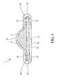
- Figure 3 is a cross-sectional view, in an enlarged form, taken along line B-B of Figure 1 ;
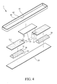
- Figure 4 is an exploded view of Figure 1 ;
- Figure 5 is a schematic view showing the physiological signal detection device of Figure 2 with an edge enclosure band, sewing threads, and an extension conductor removed;
- Figure 6 is a schematic view showing the physiological signal detection device of Figure 2 with a connection band and extension conductors removed;
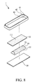
- Figure 7 is a schematic view showing a simple structure of the physiological signal detection device according to the present invention.
- Figure 8 is an exploded view of the physiological signal detection device shown in Figure 7 further comprising an edge enclosure band;
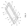
- Figure 9 is a perspective view showing the physiological signal detection device of Figure 8 after being assembled
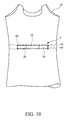
- Figure 10 is rear view showing the physiological signal detection device according to the present invention coupled to a back of a garment.
- Figure 11 is a front view showing the physiological signal detection device according to the present invention coupled to a front-open garment.
- a physiological signal detection device constructed in accordance with the present invention, generally designated at 1, comprises a combination of at least one electrode pad 11, a base layer 20, and at least one projection 30.
- the electrode pad 11 functions to set in contact with a surface of human body.
- the projection 30 is arranged to correspond to the electrode pad 11.
- the base layer 20 is directly attachable to or coupleable to a wearable article (such as garment 50 of Figure 10 ).
- the physiological signal detection device 1 has a simple structure of which the assembled configuration is illustrated in Figure 7 , which is embodied in the form of a single electrode pad 11.
- the electrode pad 11 is positioned on a top surface of the base layer 20 in such a way that the electrode pad 11 and the base layer 20 form therebetween a first receiving compartment S1.
- the projection 30 is received and fixed in the first receiving compartment S1.
- the projection 30 has at least one raised surface 31, and the raised surface 31 of the projection 30 supports and raises the electrode pad 11.
- the present invention when attached to the surface of human body, may be set in compliance with the surface curve of the human body to tightly attach thereto.
- the projection 30 is set in alignment with and supports and raises the electrode pad 11 so as to make a face of the electrode pad 11 projecting upward, whereby when observed from outside, the local face of the electrode pad 11 shows a projecting configuration to help tightly engage (or tightly abut against) the surface of human body with substantially no gap existing therebetween to allow electrical current on the surface of human body to be easily transmitted to the electrode pad 11 and facilitating detection of variation of physiological signal.
- the physiological signal detection device 1 can be embodied in various formed according different number of electrode pads 11 used.
- a wearable article such as a wrist band or a wrist protector, not shown
- an electronic device such as a multimedia playing device, not shown
- an accessory such as an earphone, not shown
- the physiological signal detection device 1 of the present invention is not limited to being mounted to wrist and may, as shown in Figure 11 , be coupled to a garment 50 in such a way that two electrode pads 11 that are mounted inside the garment 50 form a detection circuit.
- the projection 30 comprises an opposite surface 32, which can be embodied in a raised form (not shown) or a flat form (see Figure 3 ).
- the opposite surface 32 is embodied in a flat form in such a way that the overall configuration of the projection 30 is converging from the opposite surface 32 toward the raised surface 31, so that besides contact area between the opposite surface 32 of the projection 30 and the base layer 20 being increased, contact area between the raised surface 31 of the projection 30 and the electrode pad 11 is also increased to ensure a tight engagement.
- the projection 30 is securely positioned in the first receiving compartment S1 against sliding and shaking and the raised surface 31 is made in alignment with and supporting the electrode pad 11 is a projecting manner, reducing gap between the raised surface 31 and the electrode pad 11.
- the electrode pad 11 is provided with a plurality of mesh pores 111 (see Figures 1 and 4 ) to block foreign objects, such as dusts, from penetrating into the electrode pad 11 so as to reduce interference with conductive portions inside the electrode pad 11 and minimizes generation of noise.
- the projection 30 can be embodied with foam, silicone rubber, cotton fabric, or elastic objects for easy manufacture.
- the projection 30 is made of an elastic object, the projection shows resiliency and is expandable or compressible and is prone to bending and folding and may resume the original shape thereafter so as to easily comply with the curve of surface of human body when attached to the surface of human body thereby facilitating easy use and replacement.
- the base layer 20 may comprise a fabric layer, a plastic sheet, or a layer of polyester fibers.
- the at least one electrode pad 11 can be a plurality of electrode pads 11, and the at least one projection 30 can be a plurality of projections 30.
- the term "a plurality of” refers to a number that is equal to or greater than two.
- An example of the present invention shown in Figure 5 (in combination with Figures 1 , 2 , and 4 ) comprises two electrode pads 11 used in combination with two projections 30.
- the two electrode pads 11 are arranged, in a mutually spaced manner, on the top surface of the base layer 20 in such a way that each of the electrode pads 11 forms a first receiving compartment S1 with respect to the base layer 20 and each of the projections 30 is received and retained in each of the first receiving compartments S1.
- Each of the projections 30 has at least one raised surface 31, and the raised surface 31 of each of the projections 30 supports and raises each of the electrode pads 11. Further, at least one connection band 12 is connected between any two adjacent ones of the electrode pads 11 in such a way that opposite ends of the connection band 12 are respectively coupled to the two adjacent electrode pads 11, whereby a second receiving compartment S2 is formed between the connection band 12 and the base layer 20. The electrode pads 11 and the connection band 12 are jointed together to form the top layer 10 that corresponds in shape to the base layer 20.
- the electrode pads 11 can efficiently attached to opposite sides of a portion of human body (such as left and right sides of a head, left and right side parts of a back, or opposite portions of chest and back of a heart-associated portion).
- the second receiving compartment S2 functions to receive and retain other objects (such as electrical wires, sensors, and controllers). In case that no article or object is received in the second receiving compartment S2, the connection band 12 is bonded to the top surface of the base layer 20.
- connection made between each of the electrode pads 11 and the base layer 20 and the connection band 12, and connection made between the connection band 12 and the base layer 20 include sewing (being stitched with threads), adhesives (being bonded with application of adhesives) or thermal fusion (being first cut and heating applied to the cut site for fusion and jointing) to ensure secure connection.
- the physiological signal detection device 1 further comprises an edge enclosure band 40, of which the structure of embodiment is shown in Figures 2 and 3 .
- the edge enclosure band 40 has a lower flange 41 that is coupled to an edge portion of a bottom surface of the base layer 20 and the edge enclosure band 40 also has an upper flange 42 that is coupled to an edge portion of a top surface of the top layer 10 (which is composed of the connected electrode pads 11 and connection band 12).
- the edge portion of the top surface of the top layer 10 corresponds to the edge portion of the bottom surface of the base layer 20 so as to allow the edge enclosure band 40 to effect enclosure and retention for improving comfortableness and aesthetics.
- the connection band 12 is optionally provided based on the practical needs.
- the present invention can be embodied as shown in Figure 6 to arrange two mutually-spaced electrode pads 11 on a top surface of the base layer 20 with the upper flange 42 of the edge enclosure band 40 being only coupled to the edge portions of top surfaces of the two electrode pads 11.
- a garment 50 see Figures 10 an 11
- sewing thread 60 is applied along the edge enclosure band 40 to prevent mistakenly penetrating through the projection and thus damaging the structure.
- the present invention is applicable in combination with a garment 50, which, when worn by an inspection subject, allows the two electrode pads 11 to be quickly set corresponding to and conveniently attached, in a tight engagement, to the portion to be inspected, eliminating the need for separately attaching the pads.
- the edge enclosure band 40 can be embodied in combination with the previously discussed simple structure embodiment of the physiological signal detection device 1 (such a simple structure embodiment being shown in Figure 7 and a combined embodiment being shown in Figure 9 ) in such a way that the lower flange 41 of the edge enclosure band 40 is coupled to an edge portion of a bottom surface of the base layer 20, and the upper flange 42 of the edge enclosure band 40 is coupled to an edge portion of a top surface of the electrode pad 11, in which the edge portion of the top surface of the electrode pad 11 corresponds to the edge portion of the bottom surface of the base layer 20 in order to facilitate enclosure and retention effected by the edge enclosure band 40 and to improve comfortableness and aesthetics and help attaching to the garment 50.
- each of the electrode pads 11 is provided with at least one extension conductor 13 (which is particularly shown in the enlarged view at left lower corner of Figure 2 ) connected thereto.
- the extension conductor 13 has an end extending into and electrically connected to the electrode pad 11 and the extension conductor 13 has an opposite end projecting beyond an end of the electrode pad 11, whereby easy electrical connection of the extension conductor 13 of the electrode pad 11 can be made with electrical current of the surface of human body when the electrode pad 11 is supported and raised by the projection 30.
- the extension conductor 13 discussed above can also be included. Further, when the present invention is embodied with more than two electrode pads 11, based on the sizes thereof, the electrode pads 11 can be selectively provided with and coupled to extension conductors 13.
- the extension conductor 13 discussed above for the electrode pad 11 is formed by composing a plurality of conductive yarns that are provided for weaving purposes and are relatively flexible.
- the extension conductor 13 is electrically connected to an electrical wire (not shown), which has an opposite end electrically connected to physiological detection equipment (not shown), whereby electrical current of body surface flows through the electrode pad 11, the extension conductor 13, and the electrical wire to enter the physiological detection equipment.
- the extension conductor 13 is not a necessary component and the electrode pad 11 is directly and electrically connected to the electrical wire (not shown).
- the present invention provides a physiological signal detection device, which comprises a combined structure of at least one electrode pad 11, a base layer 20, and at least one projection 30 to provide a prominent projection for easy contact with and secure engagement with a surface of human body in order to facilitate detection of physiological signal of an inspection subject and improve convenience of operation.
- a physiological signal detection device which comprises a combined structure of at least one electrode pad 11, a base layer 20, and at least one projection 30 to provide a prominent projection for easy contact with and secure engagement with a surface of human body in order to facilitate detection of physiological signal of an inspection subject and improve convenience of operation.
- an edge enclosure band 40 is also included to provide function of positioning, improving comfortableness and aesthetics, and reducing influence on conduction of electrical current and lowering noise interference.
Landscapes
- Health & Medical Sciences (AREA)
- Life Sciences & Earth Sciences (AREA)
- Heart & Thoracic Surgery (AREA)
- Medical Informatics (AREA)
- Biophysics (AREA)
- Pathology (AREA)
- Engineering & Computer Science (AREA)
- Biomedical Technology (AREA)
- Cardiology (AREA)
- Physics & Mathematics (AREA)
- Molecular Biology (AREA)
- Surgery (AREA)
- Animal Behavior & Ethology (AREA)
- General Health & Medical Sciences (AREA)
- Public Health (AREA)
- Veterinary Medicine (AREA)
- Measurement And Recording Of Electrical Phenomena And Electrical Characteristics Of The Living Body (AREA)
Priority Applications (1)
| Application Number | Priority Date | Filing Date | Title |
|---|---|---|---|
| EP12172741.6A EP2676602A1 (fr) | 2012-06-20 | 2012-06-20 | Dispositif de détection de signal physiologique |
Applications Claiming Priority (1)
| Application Number | Priority Date | Filing Date | Title |
|---|---|---|---|
| EP12172741.6A EP2676602A1 (fr) | 2012-06-20 | 2012-06-20 | Dispositif de détection de signal physiologique |
Publications (1)
| Publication Number | Publication Date |
|---|---|
| EP2676602A1 true EP2676602A1 (fr) | 2013-12-25 |
Family
ID=46754234
Family Applications (1)
| Application Number | Title | Priority Date | Filing Date |
|---|---|---|---|
| EP12172741.6A Withdrawn EP2676602A1 (fr) | 2012-06-20 | 2012-06-20 | Dispositif de détection de signal physiologique |
Country Status (1)
| Country | Link |
|---|---|
| EP (1) | EP2676602A1 (fr) |
Cited By (3)
| Publication number | Priority date | Publication date | Assignee | Title |
|---|---|---|---|---|
| GB2516214A (en) * | 2013-05-22 | 2015-01-21 | Rosnes Ltd | Smart wearables |
| JP2017140213A (ja) * | 2016-02-10 | 2017-08-17 | 日本電信電話株式会社 | ウェアラブル電極 |
| CN110300543A (zh) * | 2016-09-27 | 2019-10-01 | 阿吉斯自动化技术有限公司 | 无线生命体征监测 |
Citations (8)
| Publication number | Priority date | Publication date | Assignee | Title |
|---|---|---|---|---|
| US4433481A (en) * | 1980-05-15 | 1984-02-28 | Roman Szpur | Method of mounting medical electrode assembly |
| US20050107713A1 (en) * | 2002-03-29 | 2005-05-19 | Koninklijke Philips Electronics N.V. | Monitoring system comprising electrodes with projections |
| WO2006055996A2 (fr) * | 2004-11-23 | 2006-06-01 | Nessler Medizintechnik Gmbh | Procede permettant d'etablir un contact traversant dans une matiere de support electriquement isolante |
| EP2033575A1 (fr) * | 2007-09-06 | 2009-03-11 | Covidien AG | Procédé de fabrication par étape ou continue d'électrodes biomédicales multiples à usage unique et système d'électrodes ainsi formé |
| US20090203984A1 (en) * | 2005-09-29 | 2009-08-13 | Smartlife Technology Limited | Contact sensors |
| US20090227856A1 (en) * | 2007-12-21 | 2009-09-10 | Brian Keith Russell | Electrocardiogram sensor |
| US20100036230A1 (en) * | 2008-08-06 | 2010-02-11 | Flexcon Company, Inc. | Multiple Electrode Composite Systems and Methods for Use in Electrocardiogram Detection Systems |
| US20100324405A1 (en) * | 2007-07-26 | 2010-12-23 | Koninklijke Philips Electronics N.V. | Electrode for acquiring physiological signals of a recipient |
-
2012
- 2012-06-20 EP EP12172741.6A patent/EP2676602A1/fr not_active Withdrawn
Patent Citations (8)
| Publication number | Priority date | Publication date | Assignee | Title |
|---|---|---|---|---|
| US4433481A (en) * | 1980-05-15 | 1984-02-28 | Roman Szpur | Method of mounting medical electrode assembly |
| US20050107713A1 (en) * | 2002-03-29 | 2005-05-19 | Koninklijke Philips Electronics N.V. | Monitoring system comprising electrodes with projections |
| WO2006055996A2 (fr) * | 2004-11-23 | 2006-06-01 | Nessler Medizintechnik Gmbh | Procede permettant d'etablir un contact traversant dans une matiere de support electriquement isolante |
| US20090203984A1 (en) * | 2005-09-29 | 2009-08-13 | Smartlife Technology Limited | Contact sensors |
| US20100324405A1 (en) * | 2007-07-26 | 2010-12-23 | Koninklijke Philips Electronics N.V. | Electrode for acquiring physiological signals of a recipient |
| EP2033575A1 (fr) * | 2007-09-06 | 2009-03-11 | Covidien AG | Procédé de fabrication par étape ou continue d'électrodes biomédicales multiples à usage unique et système d'électrodes ainsi formé |
| US20090227856A1 (en) * | 2007-12-21 | 2009-09-10 | Brian Keith Russell | Electrocardiogram sensor |
| US20100036230A1 (en) * | 2008-08-06 | 2010-02-11 | Flexcon Company, Inc. | Multiple Electrode Composite Systems and Methods for Use in Electrocardiogram Detection Systems |
Cited By (5)
| Publication number | Priority date | Publication date | Assignee | Title |
|---|---|---|---|---|
| GB2516214A (en) * | 2013-05-22 | 2015-01-21 | Rosnes Ltd | Smart wearables |
| GB2516214B (en) * | 2013-05-22 | 2018-01-17 | Rosnes Ltd | Smart wearables |
| JP2017140213A (ja) * | 2016-02-10 | 2017-08-17 | 日本電信電話株式会社 | ウェアラブル電極 |
| CN110300543A (zh) * | 2016-09-27 | 2019-10-01 | 阿吉斯自动化技术有限公司 | 无线生命体征监测 |
| CN110300543B (zh) * | 2016-09-27 | 2023-07-07 | 阿吉斯自动化技术有限公司 | 无线生命体征监测 |
Similar Documents
| Publication | Publication Date | Title |
|---|---|---|
| US20130338471A1 (en) | Physiological signal detection device | |
| US9008748B2 (en) | Waterproof physiological signal detection device | |
| US20230070192A1 (en) | Wearable Device | |
| JP6507254B2 (ja) | 生体情報測定装置 | |
| JP3153409U (ja) | ドライ式生体信号検出用電極 | |
| KR101687154B1 (ko) | 전도성 실을 이용한 생체신호 감지용 센서모듈 | |
| US20150201856A1 (en) | Electrode and measuring device for acquiring biomedical vital parameters | |
| CN206355043U (zh) | 一种用于采集动态心电信号的电极带 | |
| US20150157265A1 (en) | Physiological detection module | |
| EP2676602A1 (fr) | Dispositif de détection de signal physiologique | |
| JP2018078949A (ja) | 生体信号検出装具および生体信号検出方法 | |
| US9144386B2 (en) | Physiological signal detection device | |
| CN203776898U (zh) | 柔性心电电极 | |
| TW201639524A (zh) | 生理訊號感測模組 | |
| JP3177243U (ja) | 生体信号検知器 | |
| CN108209906A (zh) | 织物电极及具有该织物电极的衣服 | |
| EP2695575A1 (fr) | Dispositif étanche de détection de signal physiologique | |
| EP2684516B1 (fr) | Dispositif amélioré de détection de signal physiologique | |
| CN204260742U (zh) | 一种心电采集服装 | |
| CN102715901A (zh) | 一次性脑电监测电极 | |
| CN217793010U (zh) | 心电采集设备 | |
| JP3177095U (ja) | 生体信号検知器 | |
| KR101961728B1 (ko) | 생체신호 측정기능을 갖는 스마트 의류 및 그 제조방법 | |
| TWM437160U (en) | Physiological signals detection structural | |
| CN202654124U (zh) | 生理信号侦测结构 |
Legal Events
| Date | Code | Title | Description |
|---|---|---|---|
| PUAI | Public reference made under article 153(3) epc to a published international application that has entered the european phase |
Free format text: ORIGINAL CODE: 0009012 |
|
| AK | Designated contracting states |
Kind code of ref document: A1 Designated state(s): AL AT BE BG CH CY CZ DE DK EE ES FI FR GB GR HR HU IE IS IT LI LT LU LV MC MK MT NL NO PL PT RO RS SE SI SK SM TR |
|
| AX | Request for extension of the european patent |
Extension state: BA ME |
|
| STAA | Information on the status of an ep patent application or granted ep patent |
Free format text: STATUS: THE APPLICATION IS DEEMED TO BE WITHDRAWN |
|
| 18D | Application deemed to be withdrawn |
Effective date: 20140626 |