EP2676641A2 - Elément d'insertion et le dispositif d'insertion - Google Patents
Elément d'insertion et le dispositif d'insertion Download PDFInfo
- Publication number
- EP2676641A2 EP2676641A2 EP13159311.3A EP13159311A EP2676641A2 EP 2676641 A2 EP2676641 A2 EP 2676641A2 EP 13159311 A EP13159311 A EP 13159311A EP 2676641 A2 EP2676641 A2 EP 2676641A2
- Authority
- EP
- European Patent Office
- Prior art keywords
- insertion element
- circumferential
- segments
- circumferential segments
- type
- Prior art date
- Legal status (The legal status is an assumption and is not a legal conclusion. Google has not performed a legal analysis and makes no representation as to the accuracy of the status listed.)
- Granted
Links
Images




Classifications
-
- A—HUMAN NECESSITIES
- A61—MEDICAL OR VETERINARY SCIENCE; HYGIENE
- A61F—FILTERS IMPLANTABLE INTO BLOOD VESSELS; PROSTHESES; DEVICES PROVIDING PATENCY TO, OR PREVENTING COLLAPSING OF, TUBULAR STRUCTURES OF THE BODY, e.g. STENTS; ORTHOPAEDIC, NURSING OR CONTRACEPTIVE DEVICES; FOMENTATION; TREATMENT OR PROTECTION OF EYES OR EARS; BANDAGES, DRESSINGS OR ABSORBENT PADS; FIRST-AID KITS
- A61F2/00—Filters implantable into blood vessels; Prostheses, i.e. artificial substitutes or replacements for parts of the body; Appliances for connecting them with the body; Devices providing patency to, or preventing collapsing of, tubular structures of the body, e.g. stents
- A61F2/95—Instruments specially adapted for placement or removal of stents or stent-grafts
- A61F2/962—Instruments specially adapted for placement or removal of stents or stent-grafts having an outer sleeve
- A61F2/966—Instruments specially adapted for placement or removal of stents or stent-grafts having an outer sleeve with relative longitudinal movement between outer sleeve and prosthesis, e.g. using a push rod
-
- A—HUMAN NECESSITIES
- A61—MEDICAL OR VETERINARY SCIENCE; HYGIENE
- A61M—DEVICES FOR INTRODUCING MEDIA INTO, OR ONTO, THE BODY; DEVICES FOR TRANSDUCING BODY MEDIA OR FOR TAKING MEDIA FROM THE BODY; DEVICES FOR PRODUCING OR ENDING SLEEP OR STUPOR
- A61M25/00—Catheters; Hollow probes
- A61M25/0021—Catheters; Hollow probes characterised by the form of the tubing
- A61M25/0023—Catheters; Hollow probes characterised by the form of the tubing by the form of the lumen, e.g. cross-section, variable diameter
-
- A—HUMAN NECESSITIES
- A61—MEDICAL OR VETERINARY SCIENCE; HYGIENE
- A61F—FILTERS IMPLANTABLE INTO BLOOD VESSELS; PROSTHESES; DEVICES PROVIDING PATENCY TO, OR PREVENTING COLLAPSING OF, TUBULAR STRUCTURES OF THE BODY, e.g. STENTS; ORTHOPAEDIC, NURSING OR CONTRACEPTIVE DEVICES; FOMENTATION; TREATMENT OR PROTECTION OF EYES OR EARS; BANDAGES, DRESSINGS OR ABSORBENT PADS; FIRST-AID KITS
- A61F2250/00—Special features of prostheses classified in groups A61F2/00 - A61F2/26 or A61F2/82 or A61F9/00 or A61F11/00 or subgroups thereof
- A61F2250/0014—Special features of prostheses classified in groups A61F2/00 - A61F2/26 or A61F2/82 or A61F9/00 or A61F11/00 or subgroups thereof having different values of a given property or geometrical feature, e.g. mechanical property or material property, at different locations within the same prosthesis
- A61F2250/0018—Special features of prostheses classified in groups A61F2/00 - A61F2/26 or A61F2/82 or A61F9/00 or A61F11/00 or subgroups thereof having different values of a given property or geometrical feature, e.g. mechanical property or material property, at different locations within the same prosthesis differing in elasticity, stiffness or compressibility
-
- A—HUMAN NECESSITIES
- A61—MEDICAL OR VETERINARY SCIENCE; HYGIENE
- A61M—DEVICES FOR INTRODUCING MEDIA INTO, OR ONTO, THE BODY; DEVICES FOR TRANSDUCING BODY MEDIA OR FOR TAKING MEDIA FROM THE BODY; DEVICES FOR PRODUCING OR ENDING SLEEP OR STUPOR
- A61M25/00—Catheters; Hollow probes
- A61M25/0021—Catheters; Hollow probes characterised by the form of the tubing
- A61M25/0023—Catheters; Hollow probes characterised by the form of the tubing by the form of the lumen, e.g. cross-section, variable diameter
- A61M2025/0024—Expandable catheters or sheaths
-
- A—HUMAN NECESSITIES
- A61—MEDICAL OR VETERINARY SCIENCE; HYGIENE
- A61M—DEVICES FOR INTRODUCING MEDIA INTO, OR ONTO, THE BODY; DEVICES FOR TRANSDUCING BODY MEDIA OR FOR TAKING MEDIA FROM THE BODY; DEVICES FOR PRODUCING OR ENDING SLEEP OR STUPOR
- A61M25/00—Catheters; Hollow probes
- A61M25/0043—Catheters; Hollow probes characterised by structural features
- A61M25/0045—Catheters; Hollow probes characterised by structural features multi-layered, e.g. coated
- A61M2025/0046—Coatings for improving slidability
-
- A—HUMAN NECESSITIES
- A61—MEDICAL OR VETERINARY SCIENCE; HYGIENE
- A61M—DEVICES FOR INTRODUCING MEDIA INTO, OR ONTO, THE BODY; DEVICES FOR TRANSDUCING BODY MEDIA OR FOR TAKING MEDIA FROM THE BODY; DEVICES FOR PRODUCING OR ENDING SLEEP OR STUPOR
- A61M25/00—Catheters; Hollow probes
- A61M25/01—Introducing, guiding, advancing, emplacing or holding catheters
- A61M25/06—Body-piercing guide needles or the like
- A61M25/0662—Guide tubes
- A61M2025/0681—Systems with catheter and outer tubing, e.g. sheath, sleeve or guide tube
-
- A—HUMAN NECESSITIES
- A61—MEDICAL OR VETERINARY SCIENCE; HYGIENE
- A61M—DEVICES FOR INTRODUCING MEDIA INTO, OR ONTO, THE BODY; DEVICES FOR TRANSDUCING BODY MEDIA OR FOR TAKING MEDIA FROM THE BODY; DEVICES FOR PRODUCING OR ENDING SLEEP OR STUPOR
- A61M25/00—Catheters; Hollow probes
- A61M25/10—Balloon catheters
- A61M2025/1043—Balloon catheters with special features or adapted for special applications
- A61M2025/1081—Balloon catheters with special features or adapted for special applications having sheaths or the like for covering the balloon but not forming a permanent part of the balloon, e.g. retractable, dissolvable or tearable sheaths
-
- A—HUMAN NECESSITIES
- A61—MEDICAL OR VETERINARY SCIENCE; HYGIENE
- A61M—DEVICES FOR INTRODUCING MEDIA INTO, OR ONTO, THE BODY; DEVICES FOR TRANSDUCING BODY MEDIA OR FOR TAKING MEDIA FROM THE BODY; DEVICES FOR PRODUCING OR ENDING SLEEP OR STUPOR
- A61M25/00—Catheters; Hollow probes
- A61M25/0043—Catheters; Hollow probes characterised by structural features
- A61M25/005—Catheters; Hollow probes characterised by structural features with embedded materials for reinforcement, e.g. wires, coils, braids
Definitions
- the invention relates to an insertion element and an insertion device according to the preambles of the independent claims.
- implants are often used, which are introduced permanently or at least for a longer period of time in an animal and / or human body to fulfill replacement functions.
- These include, for example, pacemakers, brain pacemakers for Parkinson's patients, cardiac implants, cochlear implants, retinal implants, dental implants, implants for joint replacement, vascular prostheses or stents.
- Implants are connected to catheters prior to insertion into the body, allowing them to be accurately placed and defined at the site of use.
- a hose-like insertion element is used for this purpose, through which the implant is pushed by means of the insertion device.
- an insertion known which is only expanded when passing the implant to the necessary larger diameter.
- the insertion element consists of two to three coaxially arranged layers, wherein the outer is provided with longitudinal slots, which allows the enlargement of the diameter.
- the invention has for its object to provide an insertion, which is simplified in its manufacture and which allows improved flexibility of the insertion.
- Another object is to provide a corresponding insertion device.
- the insertion element which is designed to cooperate with an insertion device for introducing a medical implant into a human or animal body.
- the insertion element has a shell, which has at least two types of circumferential segments with different elasticity in the circumferential direction.
- a circumferential segment of the sheath is to be understood as meaning a region of the sheath which may be formed as a narrow strip almost as a complete lateral surface of the sheath.
- a shell is to be understood as a body that is formed integrally, in particular material-locking, from one or more fabric components, in other words, that at least two types of circumferential segments are made in one piece with one another.
- integral is understood to mean that the circumferential segments of the at least two types can only be separated from one another with loss of function of at least one of the peripheral segments.
- the elasticity in particular the modulus of elasticity of the material of the first type of circumferential segment of the material of the second type of circumferential segment under otherwise identical conditions, in particular at least a factor of 2 differs.
- the extensibility, especially the elongation at yield, of the materials of the first type of circumferential segment and of the second type of circumferential segment should differ significantly under otherwise identical conditions.
- circumferential segments One of the types of circumferential segments is elastic. Under elastic should be understood in particular that the respective circumferential segment reversibly resumes its original dimensions after an expansion in which the diameter of the insertion is increased.
- one type of the at least two circumferential segments may be substantially stiffer than the other type of the at least two circumferential segments. It is advantageously achieved that the insertion element is formed on the one hand mechanically stable. Thereby, the flexibility of the insertion element in the use state can be improved. An undesirable kinking of the insertion element at tight curve radii, as may occur in a longitudinal slot inserter, can be reliably avoided. On the other hand, a reversible diameter enlargement is made possible, which allows easy passage of the implant within the insertion element.
- a favorable configuration may provide a tubular configuration of the insertion element, wherein the at least two types of circumferential segments may extend along a longitudinal extension of the insertion element or may be arranged.
- the respective circumferential segments can be formed over the entire length of the insertion element with constant widths relative to the circumference, which is particularly easy to produce.
- the widths of the various and / or similar circumferential segments vary along the length of the insertion element, so that a variable-length extensibility of the insertion element can be provided.
- one type of circumferential segment may comprise thermoplastic material.
- Suitable materials are polyether ether ketone (PEEK), polyimide (PI) Polyether ketone ketone (PEKK), polyamides, polyesters, polyethylene (PE), polypropylene (PP), polycarbonate (PC).
- PEEK polyether ether ketone
- PI polyimide
- PEKK Polyether ketone ketone
- PA-12 polyamide 12
- polyester for example polyethylene terephthalate, known as PET.
- another type of circumferential segment may comprise a thermoplastic, the class of thermoplastic elastomer (TPE).
- TPE thermoplastic elastomer
- Suitable are thermoplastic elastomers selected from olefin-based thermoplastic elastomers TPE-O (TPO), urethane-based thermoplastic elastomers TPE-U (TPU), styrene block copolymers TPE-S (TPS), thermoplastic copolyester TPE-E or thermoplastic copolyamides TPE-A ( TPA) or combinations thereof.
- TPO olefin-based thermoplastic elastomers
- TPU urethane-based thermoplastic elastomers
- TPS styrene block copolymers
- TPE-E thermoplastic copolyester
- TPA thermoplastic copolyamides
- polyamide elastomers e.g. Polyether block amide block copolymers (PEBA), for example PEBAX (
- the at least first and second types of circumferential segments may be formed by mutually compatible materials. These can be easily assembled by simple material connection at the melting point to a closed shell of the insertion.
- a thermoplastic material may be combined with a thermoplastic elastomer, for example polyamide PA-12 with a polyamide elastomer or polyester with a polyester elastomer.
- the shell may be formed with the various circumferential segments by co-extrusion.
- This is a particularly simple production possibility of the insertion element, in which the different but mutually compatible materials of the peripheral segments of the shell can be connected to each other with simultaneous formation of the shell. It is not necessary to add several concentric layers of material to a shell. There is also no need for post-processing to incorporate apertures or slots in the sleeve to allow it to expand in diameter.
- the circumferentially variable elasticity of the sheath while maintaining sufficient strength is an intrinsic feature of the sheath and allows for reversible expansion of the insertion element when passing the implant, allowing a quick and gentle insertion and placement of the implant.
- At least one stabilizing element can be arranged in at least one of the circumferential segments along a longitudinal extent of the insertion element or the sleeve.
- the at least one stabilizing element is arranged in the region of the shell, which is the less extensible region and / or in the larger area of the shell (matrix).
- the stabilizing element may in particular extend at least over a predetermined area continuously in the axial direction of the insertion element or the shell.
- the stabilizing element may advantageously be designed, for example, as a wire or as a wire bundle, as a fiber or fiber bundle or a mixture of one or more embodiments.
- the sheath may be equipped with one or more stabilizing elements at the distal end in the installed state and, on the other hand, may be free of stabilizing elements at the proximal end.
- a reverse arrangement is also conceivable.
- the above-mentioned stabilization elements can be made profiled.
- the profiling is preferably designed so that the inner contact surface of the stabilizing element of the insertion element is reduced.
- the friction is reduced, so that the implant can be inserted more easily.
- the profiling of the / stabilizing element (s) the amount of material of the individual stabilizing elements can be increased, whereby the introduction element is altogether stiffer and easier to push.
- the sheath may be extruded on the distal or proximal end (in the installed state of the sheath) from at least two compatible materials forming the various circumferential segments of the sheath.
- the main material, ie the matrix is additionally reinforced with a stabilizing element or with several stabilizing elements, which are incorporated in the extrusion with, and gives the extruded shell advantageous mechanical properties for the insertability of the shell and the displacement properties of the shell along the insertion device.
- the expandability of the diameter of the envelope is effected by the properties of the at least two types of circumferential segments.
- the medical implant for example a self-expanding prosthesis such as a stent or a heart valve, must be placed in a defined position and released by the introducer.
- the sheath stabilized with stabilizing elements can, if necessary, be pushed from the proximal end of the introducer onto the outer shaft and in the direction of the implant at the distal end.
- the one or more stabilizing elements allow a secure sliding of the shell.
- the sheath can be pushed over the implant and this can be covered and repositioned or gently removed again completely. It is particularly advantageous that the surface of the shell is smooth, so that the risk of entanglement is reduced. Sharp edges, tips and slits are safely covered by the cover.
- a friction-reducing coating may be provided on the sheath. This facilitates the handling of the introducer and its use in an introducer and can be done faster and thus less stressful for a patient.
- the coating may be a hydrophobic coating or a hydrophilic coating.
- the coating may be disposed on the inside of the shell, on the outside of the shell or on the inside and outside of the shell. It can be hydrophilic on both sides or hydrophobic on both sides, or hydrophilic on the inside and hydrophobic on the outside, or hydrophobic on the inside, and hydrophilic on the outside.
- the one type of circumferential segments may be considered to be a narrow strip extending in the longitudinal extent of the sleeve, serving as a matrix second type of circumferential segments embedded.
- a strip may be provided, or two or more strips may be provided.
- the number of stripes may be selected depending on the materials used for the first and / or second circumferential segment and / or desired elongation properties of the sheath. It can also be selected depending on demand, whether the material is arranged with higher or lower elasticity in the strip or in the matrix.
- the sheath may have in the circumferential direction at least two circumferential segments of one kind, which are separated by a circumferential segment of the other type. This results in a particularly simple geometry of the shell when expanding the diameter.
- an insertion device for introducing a medical implant into a human or animal body comprising at least one outer insertion element, which is at least partially elastically expandable in the use state, wherein the outer insertion element is designed as a lock, through which an outer shaft surrounding an inner shaft on which inner shaft a medical implant for introduction into a human or animal body is arranged, is insertable to a place of use.
- the outer insertion element in this case comprises a shell, which has at least two types of circumferential segments with different elasticity in the circumferential direction. Due to the expansibility of the insertion element in the implementation of the implant or a catheter with implant, the opening in the body for insertion of the implant may be smaller than if a lock with a maximum required diameter would be used.
- an insertion device for introducing a medical implant into a human or animal body comprising at least one outer insertion element, wherein the outer insertion element is formed at least as a distal end of an outer shaft surrounding an inner shaft, and the one on the inner shaft arranged medical implant covers at least before or during insertion into a human or animal body, wherein the outer insertion in the use state, at least partially elastically expandable is.
- the outer insertion element comprises a shell, which has at least two types of circumferential segments with different elasticity in the circumferential direction.
- the insertion element ie the outer shaft
- a mispositioned implant for example a self-expanding stent
- the pushing back of the outer shaft can be effected particularly simply and stably. Even if a repositioning of the implant would fail, the deferred introducer surrounds the implant causing less micro-trauma in the vessels as the implant is removed.
- the insertion devices according to the various aspects of the invention can also be combined, resulting in an advantageous insertion device whose outer shaft has a distal end which is at least partially elastically expandable, and which insertion device can be inserted through an elastically expandable lock.
- the lock and at least the distal end of the outer shaft have at least one of the features of the insertion element described above.
- the outer insertion element have a region in which at least in some areas at least one stabilizing element is arranged in at least one of the circumferential segments along a longitudinal extent of the sheath.
- the insertion is particularly stable.
- FIGS. 1A, 1B show a first exemplary embodiment of an insertion element 10 as a side view ( FIG. 1A ) and as a cross section ( FIG. 1B ).
- the insertion element 10 can in particular be used, for example, as a lock 80 for a catheter, or else be an immediate component of a catheter, for example an outer shaft of a catheter.
- the insertion element 10 is intended for cooperation with an insertion device 100 (FIG. FIGS. 4 . 5A . 5B ) for introducing a medical implant 20, for example a self-expanding Stent, trained in a human or animal body.
- the tubular sheath 12 of the insertion element 10 has in the circumferential direction at least two peripheral segments 16, 18 of a first and a second type with different elasticity, for example, diametrically opposed.
- the second circumferential segment 18 is formed as a narrow strip along the longitudinal extent L of the insertion element 19.
- the first peripheral segment 16 is substantially stiffer than the second peripheral segment 18.
- the first rigid peripheral member 16 is formed of polyamide PA 12, for example, and the second elastic peripheral segment 18 of polyamide elastomer.
- the introducer 10 may optionally include a friction reducing coating 70, such as on the outside of the sheath 12.
- the coating 70 may have hydrophilic or hydrophobic properties.
- FIGS. 2A, 2B show a further exemplary embodiment of an insertion element 10 as a side view ( FIG. 2A ) and as a cross section ( FIG. 2B ).
- the insertion element 10 is intended for cooperation with an insertion device 100 (FIG. FIGS. 4 . 5A . 5B ) for introducing a medical implant 20 into a human or animal body.
- the tubular sheath 12 of the insertion element 10 has in the circumferential direction at least two peripheral segments 16, 18 with different elasticity, for example, each diametrically opposite.
- the second circumferential segment 18 is formed as a wide strip along the longitudinal extent L of the insertion element 10, in which the first circumferential segment 16 is embedded as a narrow strip.
- the first circumferential segment 16 is substantially stiffer than the second circumferential segment 18.
- the first peripheral element 16 is formed, for example, of polyester, and the second circumferential segment 18 of polyester elastomer.
- the introducer 10 may optionally include a friction reducing coating 70, such as on the outside of the sheath 12.
- the coating 70 may have hydrophilic or hydrophobic properties.
- the peripheral segments 16, 18 of the shell 12 shown in the exemplary embodiments are advantageously formed by mutually compatible materials, from which the shell 12 can be produced particularly easily by co-extrusion.
- the strip-shaped circumferential segments 16 or 18 are embedded in the half shell peripheral segments 18 or 16 as in a matrix.
- the circumferential segments 16, 18 together form a circumferentially closed jacket sheath, which can be reversibly widened when the implant 20 (FIG. FIG. 1 ) passes the relevant point within the insertion element 10.
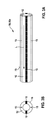
- FIGS. 3A, 3B show a further exemplary embodiment of an insertion element 10 as a side view ( FIG. 3A ) and as a cross section ( FIG. 3B ).
- the insertion element 10 has at least in regions (region 10a) in at least one of the peripheral segments 16, preferably in the region of lower extensibility along a longitudinal extent L of the shell 12 at least one stabilizing element 15, such as a wire, in particular a metallic wire.
- the stabilizing element 15 supports the mechanical stability of the insertion element 10.
- Stabilizing elements 15 may in principle be provided in one or more or all circumferential segments 16, 18, also in various circumferential segments 16, 18 with different elasticity.
- Cheap materials for the stiff (less elastic) circumferential segments 16 after the FIGS. 1 . 2 . 3 are PEEK, PI, PE, PP, PC, preferably polyamides such as PA12 (eg Grilamid L25) or polyester such as PET and polyamide elastomers with hardnesses of Shore D> 60 or polyester elastomers with hardnesses of Shore D> 60.
- Materials for the elastic peripheral segments 18 after the FIGS. 1 . 2 . 3 are TPE-O, TPE-U, preferably polyamide elastomers (TPE-A) with hardnesses of Shore D ⁇ 70 or polyester elastomers (TPE-E) with hardnesses of Shore D ⁇ 70.
- TPE-A polyamide elastomers
- TPE-E polyester elastomers
- FIG. 4 shows for illustrating the invention, a side view of a first embodiment of an introducer 100, which here, for example, comprises a catheter with which a self-expanding stent is to be introduced.
- the insertion device 100 comprises inner and outer insertion elements in the form of an inner shaft 50 and surrounding it External shaft 40, at the proximal ends of a conventional, unspecified described handle means 60 with different Rantücken, eg for flushing the lumen of or between inner shaft 50 and outer shaft 40 and to release the implant 20, is arranged. Between the oppositely located distal ends, an implant 20 with a conventional guide device 30 is arranged on the inner shaft 50.
- a flexible lock 80 e.g. introduced into the blood vessel through which catheters can slide into the blood vessel.
- the insertion element 10 embodied as a lock 80 comprises, as described in the exemplary embodiments described above, a sleeve 12 having a circumferential segment 16 of a first type and a circumferential segment 18 of a second type, the two types differing in their elasticity.
- the circumferential segment 18 of the second type is formed along the longitudinal extension of the hose-shaped insertion element 10 as a narrow strip which is embedded in the matrix-like peripheral segment 16 of the first type.
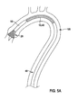
- FIGS. 5A and 5B show for illustrating the invention, a side view of another embodiment of an insertion device 100, in which an insertion element 10 is provided as the distal end of an outer shaft 40.
- the insertion element 10 includes, as described in the embodiments described above, a shell 12 having a peripheral segment 16 of a first type and a peripheral segment 18 of a second type, wherein the two types differ in their elasticity.
- the circumferential segment 18 of the second type is formed along the longitudinal extension of the hose-shaped insertion element 10 as a narrow strip which is embedded in the matrix-like peripheral segment 16 of the first type.
- the outer shaft 40 may be completely formed as an insertion element 10, or only partially, in particular at the distal end of the outer shaft 40 in the region which covers the implant 20.
- FIG. 2 shows a side view of an insertion situation of the insertion device 100 with partially released implant 20 in the form of a self-expanding stent at the distal end of the insertion device 100.
- Fig. 5B is shown in a side view, the insertion situation of an introducer 100 with re-covered implant 20 with a pushed-insertion element 10.
- the insertion element 10 may extend over the entire axial length of the insertion device 100 or the outer shaft 40, wherein advantageously at the distal end of a region 10a may be provided with one or more stabilizing elements 15.
- the introducer 10 may be slid distally from the proximal end of the introducer 100 until the stabilized region 10a of the introducer 10 is slid over the partially released implant 20 at the distal end of the outer shaft 40 completely covered again.
- the implant 20 can also be gently removed from the body in this state, since the insertion element 10 covers sharp edges or pointed parts of the implant.
- the insertion element 10 according to the invention can advantageously be used as a sluice 80 to introduce the insertion device 100 into a human or animal body, and additionally or alternatively as an outer shaft 40 or part of the outer shaft 40 for re-sheathing a partially released implant 20 be used.
- the more stretchable of the peripheral segments 16, 18 can have, for example, an up to four times higher elongation than the less extensible peripheral segments 16, 18.
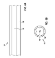
- Fig. 6A is a side view of an embodiment of an insertion element 10 as it can be used, for example, in conjunction with an insertion device 100 for introducing an implant 20 into a human or animal body.
- Fig. 6B is the embodiment of an insertion after Fig. 6A shown in cross section.
- the insertion element 10 can thus be used, for example, as a lock 80 for a catheter.
- the insertion element 10 of this embodiment has at least 2 different peripheral elements 16, 18 of a first and a second type with different elasticity.
- the peripheral elements 16 have a higher rigidity and a lower elasticity than the peripheral elements 18.
- the peripheral elements 16 are formed as profiled metal strips and embedded in a polyamide elastomer, which forms the peripheral elements 18.
- the peripheral elements 16 are profiled such that a tip 16 has a formed in the interior of the insertion element 10.
- the contact surface between the functioning, for example, as a lock 80 insertion element 10 and the catheter to be inserted is reduced.
- an easier sliding of the catheter in the insertion element 10 can be achieved.
- the rigidity of the entire insertion element 10 can be increased, whereby the insertion element itself can be pushed more easily.
- insertion element 10 can also in an insertion device 100 as a distal end of the outer shaft 40 analogous to the Figures 5A and 5B be used.
Landscapes
- Health & Medical Sciences (AREA)
- Engineering & Computer Science (AREA)
- Biomedical Technology (AREA)
- Life Sciences & Earth Sciences (AREA)
- Veterinary Medicine (AREA)
- Animal Behavior & Ethology (AREA)
- Public Health (AREA)
- Heart & Thoracic Surgery (AREA)
- General Health & Medical Sciences (AREA)
- Oral & Maxillofacial Surgery (AREA)
- Cardiology (AREA)
- Transplantation (AREA)
- Vascular Medicine (AREA)
- Hematology (AREA)
- Pulmonology (AREA)
- Biophysics (AREA)
- Anesthesiology (AREA)
- Prostheses (AREA)
- Materials For Medical Uses (AREA)
Applications Claiming Priority (2)
| Application Number | Priority Date | Filing Date | Title |
|---|---|---|---|
| US201261660831P | 2012-06-18 | 2012-06-18 | |
| US201213709805A | 2012-12-10 | 2012-12-10 |
Publications (3)
| Publication Number | Publication Date |
|---|---|
| EP2676641A2 true EP2676641A2 (fr) | 2013-12-25 |
| EP2676641A3 EP2676641A3 (fr) | 2016-03-30 |
| EP2676641B1 EP2676641B1 (fr) | 2020-12-16 |
Family
ID=47915451
Family Applications (1)
| Application Number | Title | Priority Date | Filing Date |
|---|---|---|---|
| EP13159311.3A Active EP2676641B1 (fr) | 2012-06-18 | 2013-03-15 | Dispositif d'insertion |
Country Status (1)
| Country | Link |
|---|---|
| EP (1) | EP2676641B1 (fr) |
Cited By (7)
| Publication number | Priority date | Publication date | Assignee | Title |
|---|---|---|---|---|
| EP2979723A1 (fr) | 2014-07-30 | 2016-02-03 | Biotronik AG | Élément d'introduction |
| WO2018165519A1 (fr) * | 2017-03-10 | 2018-09-13 | Abiomed, Inc. | Gaine d'introduction extensible pour dispositif médical |
| EP3470105A1 (fr) * | 2017-10-13 | 2019-04-17 | Biotronik AG | Élément d'introduction pour un dispositif d'introduction médicale |
| EP3741420A1 (fr) * | 2015-04-10 | 2020-11-25 | Edwards Lifesciences Corporation | Gaine extensible |
| US11660434B2 (en) | 2020-02-03 | 2023-05-30 | Abiomed, Inc. | Expandable sheath with interlock dilator |
| US12558521B2 (en) | 2018-08-14 | 2026-02-24 | Abiomed, Inc. | Expandable introducer sheath for medical device |
| US12589226B2 (en) | 2018-02-15 | 2026-03-31 | Abiomed, Inc. | Expandable introducer sheath for medical device |
Family Cites Families (4)
| Publication number | Priority date | Publication date | Assignee | Title |
|---|---|---|---|---|
| US5944691A (en) * | 1996-11-04 | 1999-08-31 | Cordis Corporation | Catheter having an expandable shaft |
| WO2002083224A2 (fr) * | 2001-04-17 | 2002-10-24 | Salviac Limited | Catheter |
| WO2004037333A1 (fr) * | 2002-10-25 | 2004-05-06 | Nmt Medical, Inc. | Gaine extensible |
| US20100198160A1 (en) * | 2006-06-28 | 2010-08-05 | Abbott Vascular Inc. | Expandable Introducer Sheaths and Methods for Manufacture and Use |
-
2013
- 2013-03-15 EP EP13159311.3A patent/EP2676641B1/fr active Active
Cited By (14)
| Publication number | Priority date | Publication date | Assignee | Title |
|---|---|---|---|---|
| EP2979723A1 (fr) | 2014-07-30 | 2016-02-03 | Biotronik AG | Élément d'introduction |
| EP3741420A1 (fr) * | 2015-04-10 | 2020-11-25 | Edwards Lifesciences Corporation | Gaine extensible |
| WO2018165519A1 (fr) * | 2017-03-10 | 2018-09-13 | Abiomed, Inc. | Gaine d'introduction extensible pour dispositif médical |
| US10967152B2 (en) | 2017-03-10 | 2021-04-06 | Abiomed, Inc. | Expandable introducer sheath for medical device |
| EP3978060A1 (fr) * | 2017-03-10 | 2022-04-06 | Abiomed, Inc. | Gaine d'introduction extensible pour dispositif médical |
| US11697002B2 (en) | 2017-03-10 | 2023-07-11 | Abiomed, Inc. | Expandable introducer sheath for medical device |
| AU2018230449B2 (en) * | 2017-03-10 | 2023-10-26 | Abiomed, Inc. | Expandable introducer sheath for medical device |
| US11969563B2 (en) | 2017-03-10 | 2024-04-30 | Abiomed, Inc. | Expandable introducer sheath for medical device |
| EP3470105A1 (fr) * | 2017-10-13 | 2019-04-17 | Biotronik AG | Élément d'introduction pour un dispositif d'introduction médicale |
| US12589226B2 (en) | 2018-02-15 | 2026-03-31 | Abiomed, Inc. | Expandable introducer sheath for medical device |
| US12558521B2 (en) | 2018-08-14 | 2026-02-24 | Abiomed, Inc. | Expandable introducer sheath for medical device |
| US11660434B2 (en) | 2020-02-03 | 2023-05-30 | Abiomed, Inc. | Expandable sheath with interlock dilator |
| US12357801B2 (en) | 2020-02-03 | 2025-07-15 | Abiomed, Inc. | Expandable sheath with interlock dilator |
| US11944770B2 (en) | 2020-02-03 | 2024-04-02 | Abiomed, Inc. | Expandable sheath with interlock dilator |
Also Published As
| Publication number | Publication date |
|---|---|
| EP2676641A3 (fr) | 2016-03-30 |
| EP2676641B1 (fr) | 2020-12-16 |
Similar Documents
| Publication | Publication Date | Title |
|---|---|---|
| EP2702965B1 (fr) | Dispositif de libération pour libérer un implant médical d'un cathéter et cathéter avec dispositif de libération | |
| EP2676641B1 (fr) | Dispositif d'insertion | |
| DE60011132T2 (de) | Prothese zum kontrollieren der flussrichtung in einem körpergefäss | |
| DE69632948T2 (de) | Entfaltungssystem für endoprothetischen Stent oder Transplantat | |
| DE10334868B4 (de) | Implantierbare Einrichtung als Organklappenersatz, dessen Herstellungsverfahren sowie Grundkörper und Membranelement dafür | |
| EP2979667B2 (fr) | Dispositif d'introduction d'un implant médical dans un corps humain et/ou animal | |
| DE60125687T2 (de) | Lenkbarer Katheter mit veränderbarem Handgriff | |
| EP3213717B1 (fr) | Cathéter de livraison et arrangement de cathéter | |
| EP2612622A1 (fr) | Implant médical | |
| EP2628470B1 (fr) | Dispositif de libération destiné à libérer un implant médical d'un cathéter et cathéter avec un dispositif de libération ainsi que procédé de serrage d'un implant dans celui-ci | |
| WO2014026870A2 (fr) | Dispositif implantable destiné à être utilisé dans un corps humain et/ou animal pour remplacer un clapet organique | |
| DE102010008338A1 (de) | Einrichtung, vorgesehen, um an einem Katheter befestigt oder mit diesem verbunden zu werden, Katheter und Verfahren | |
| WO2013117718A1 (fr) | Greffon de stent muni d'éléments de fixation et d'un système d'insertion | |
| DE102015111205A1 (de) | Behandlungsvorrichtung einer Blutbahn | |
| DE102015107242A1 (de) | Implantat | |
| DE202011107781U1 (de) | Prothesenanordnung zur Implantation in oder um ein Hohlorgan | |
| EP2604233A2 (fr) | Dispositif de libération destiné à libérer un implant médical d'un cathéter et cathéter avec un dispositif de libération ainsi que procédé de fabrication d'un corps de serrage d'un dispositif de libération destiné à libérer un implant médical d'un cathéter et cathéter avec un dispositif de libération ainsi que procédé de fabrication d'un corps de serrage d'un dispositif de libération et procédé de serrage d'un implant dans ce système de serrage | |
| EP2522385B1 (fr) | Clapet élastique pour la protection de l'extrémité distale d'un cathéter dotée d'un tuyau flexible intérieur et extérieur | |
| DE102010023744B4 (de) | Vorrichtung zur Behandlung eines Blutgefäßes sowie System zum Aussetzen einer Endoprothese | |
| EP2676642A1 (fr) | Dispositif de libération pour libérer un implant médical d'un cathéter | |
| EP1685813B1 (fr) | Stent greffe | |
| DE102009023661A1 (de) | Medizinischer Katheter, medizinisches Funktionselement und Anordnung umfassend einen derartigen Katheter und ein derartiges Funktionselement | |
| EP2910221B1 (fr) | Dispositif de dégagement pour libérer un implant médical d'un cathéter ainsi que cathéter avec dispositif de dégagement | |
| EP4074364A1 (fr) | Tube médical et dispositif de liaison d'un dispositif médical | |
| DE102021113558A1 (de) | Vorrichtung zum Zuführen eines Implantats in ein Körperhohlgefäß und Anordnung mit einer solchen Vorrichtung |
Legal Events
| Date | Code | Title | Description |
|---|---|---|---|
| PUAI | Public reference made under article 153(3) epc to a published international application that has entered the european phase |
Free format text: ORIGINAL CODE: 0009012 |
|
| AK | Designated contracting states |
Kind code of ref document: A2 Designated state(s): AL AT BE BG CH CY CZ DE DK EE ES FI FR GB GR HR HU IE IS IT LI LT LU LV MC MK MT NL NO PL PT RO RS SE SI SK SM TR |
|
| AX | Request for extension of the european patent |
Extension state: BA ME |
|
| PUAL | Search report despatched |
Free format text: ORIGINAL CODE: 0009013 |
|
| AK | Designated contracting states |
Kind code of ref document: A3 Designated state(s): AL AT BE BG CH CY CZ DE DK EE ES FI FR GB GR HR HU IE IS IT LI LT LU LV MC MK MT NL NO PL PT RO RS SE SI SK SM TR |
|
| AX | Request for extension of the european patent |
Extension state: BA ME |
|
| RIC1 | Information provided on ipc code assigned before grant |
Ipc: A61M 25/10 20060101ALN20160219BHEP Ipc: A61F 2/966 20130101AFI20160219BHEP Ipc: A61M 25/00 20060101ALI20160219BHEP Ipc: A61M 25/06 20060101ALN20160219BHEP |
|
| 17P | Request for examination filed |
Effective date: 20160929 |
|
| RBV | Designated contracting states (corrected) |
Designated state(s): AL AT BE BG CH CY CZ DE DK EE ES FI FR GB GR HR HU IE IS IT LI LT LU LV MC MK MT NL NO PL PT RO RS SE SI SK SM TR |
|
| STAA | Information on the status of an ep patent application or granted ep patent |
Free format text: STATUS: EXAMINATION IS IN PROGRESS |
|
| 17Q | First examination report despatched |
Effective date: 20180830 |
|
| GRAP | Despatch of communication of intention to grant a patent |
Free format text: ORIGINAL CODE: EPIDOSNIGR1 |
|
| STAA | Information on the status of an ep patent application or granted ep patent |
Free format text: STATUS: GRANT OF PATENT IS INTENDED |
|
| INTG | Intention to grant announced |
Effective date: 20200227 |
|
| GRAJ | Information related to disapproval of communication of intention to grant by the applicant or resumption of examination proceedings by the epo deleted |
Free format text: ORIGINAL CODE: EPIDOSDIGR1 |
|
| STAA | Information on the status of an ep patent application or granted ep patent |
Free format text: STATUS: EXAMINATION IS IN PROGRESS |
|
| GRAP | Despatch of communication of intention to grant a patent |
Free format text: ORIGINAL CODE: EPIDOSNIGR1 |
|
| STAA | Information on the status of an ep patent application or granted ep patent |
Free format text: STATUS: GRANT OF PATENT IS INTENDED |
|
| INTC | Intention to grant announced (deleted) | ||
| INTG | Intention to grant announced |
Effective date: 20200724 |
|
| GRAS | Grant fee paid |
Free format text: ORIGINAL CODE: EPIDOSNIGR3 |
|
| GRAA | (expected) grant |
Free format text: ORIGINAL CODE: 0009210 |
|
| STAA | Information on the status of an ep patent application or granted ep patent |
Free format text: STATUS: THE PATENT HAS BEEN GRANTED |
|
| AK | Designated contracting states |
Kind code of ref document: B1 Designated state(s): AL AT BE BG CH CY CZ DE DK EE ES FI FR GB GR HR HU IE IS IT LI LT LU LV MC MK MT NL NO PL PT RO RS SE SI SK SM TR |
|
| REG | Reference to a national code |
Ref country code: GB Ref legal event code: FG4D Free format text: NOT ENGLISH |
|
| REG | Reference to a national code |
Ref country code: IE Ref legal event code: FG4D Free format text: LANGUAGE OF EP DOCUMENT: GERMAN |
|
| REG | Reference to a national code |
Ref country code: DE Ref legal event code: R096 Ref document number: 502013015371 Country of ref document: DE |
|
| REG | Reference to a national code |
Ref country code: AT Ref legal event code: REF Ref document number: 1344894 Country of ref document: AT Kind code of ref document: T Effective date: 20210115 |
|
| PG25 | Lapsed in a contracting state [announced via postgrant information from national office to epo] |
Ref country code: FI Free format text: LAPSE BECAUSE OF FAILURE TO SUBMIT A TRANSLATION OF THE DESCRIPTION OR TO PAY THE FEE WITHIN THE PRESCRIBED TIME-LIMIT Effective date: 20201216 Ref country code: RS Free format text: LAPSE BECAUSE OF FAILURE TO SUBMIT A TRANSLATION OF THE DESCRIPTION OR TO PAY THE FEE WITHIN THE PRESCRIBED TIME-LIMIT Effective date: 20201216 Ref country code: NO Free format text: LAPSE BECAUSE OF FAILURE TO SUBMIT A TRANSLATION OF THE DESCRIPTION OR TO PAY THE FEE WITHIN THE PRESCRIBED TIME-LIMIT Effective date: 20210316 Ref country code: GR Free format text: LAPSE BECAUSE OF FAILURE TO SUBMIT A TRANSLATION OF THE DESCRIPTION OR TO PAY THE FEE WITHIN THE PRESCRIBED TIME-LIMIT Effective date: 20210317 |
|
| REG | Reference to a national code |
Ref country code: NL Ref legal event code: MP Effective date: 20201216 |
|
| PG25 | Lapsed in a contracting state [announced via postgrant information from national office to epo] |
Ref country code: BG Free format text: LAPSE BECAUSE OF FAILURE TO SUBMIT A TRANSLATION OF THE DESCRIPTION OR TO PAY THE FEE WITHIN THE PRESCRIBED TIME-LIMIT Effective date: 20210316 Ref country code: LV Free format text: LAPSE BECAUSE OF FAILURE TO SUBMIT A TRANSLATION OF THE DESCRIPTION OR TO PAY THE FEE WITHIN THE PRESCRIBED TIME-LIMIT Effective date: 20201216 Ref country code: SE Free format text: LAPSE BECAUSE OF FAILURE TO SUBMIT A TRANSLATION OF THE DESCRIPTION OR TO PAY THE FEE WITHIN THE PRESCRIBED TIME-LIMIT Effective date: 20201216 |
|
| PG25 | Lapsed in a contracting state [announced via postgrant information from national office to epo] |
Ref country code: NL Free format text: LAPSE BECAUSE OF FAILURE TO SUBMIT A TRANSLATION OF THE DESCRIPTION OR TO PAY THE FEE WITHIN THE PRESCRIBED TIME-LIMIT Effective date: 20201216 Ref country code: HR Free format text: LAPSE BECAUSE OF FAILURE TO SUBMIT A TRANSLATION OF THE DESCRIPTION OR TO PAY THE FEE WITHIN THE PRESCRIBED TIME-LIMIT Effective date: 20201216 |
|
| REG | Reference to a national code |
Ref country code: LT Ref legal event code: MG9D |
|
| PG25 | Lapsed in a contracting state [announced via postgrant information from national office to epo] |
Ref country code: SK Free format text: LAPSE BECAUSE OF FAILURE TO SUBMIT A TRANSLATION OF THE DESCRIPTION OR TO PAY THE FEE WITHIN THE PRESCRIBED TIME-LIMIT Effective date: 20201216 Ref country code: RO Free format text: LAPSE BECAUSE OF FAILURE TO SUBMIT A TRANSLATION OF THE DESCRIPTION OR TO PAY THE FEE WITHIN THE PRESCRIBED TIME-LIMIT Effective date: 20201216 Ref country code: PT Free format text: LAPSE BECAUSE OF FAILURE TO SUBMIT A TRANSLATION OF THE DESCRIPTION OR TO PAY THE FEE WITHIN THE PRESCRIBED TIME-LIMIT Effective date: 20210416 Ref country code: LT Free format text: LAPSE BECAUSE OF FAILURE TO SUBMIT A TRANSLATION OF THE DESCRIPTION OR TO PAY THE FEE WITHIN THE PRESCRIBED TIME-LIMIT Effective date: 20201216 Ref country code: CZ Free format text: LAPSE BECAUSE OF FAILURE TO SUBMIT A TRANSLATION OF THE DESCRIPTION OR TO PAY THE FEE WITHIN THE PRESCRIBED TIME-LIMIT Effective date: 20201216 Ref country code: EE Free format text: LAPSE BECAUSE OF FAILURE TO SUBMIT A TRANSLATION OF THE DESCRIPTION OR TO PAY THE FEE WITHIN THE PRESCRIBED TIME-LIMIT Effective date: 20201216 Ref country code: SM Free format text: LAPSE BECAUSE OF FAILURE TO SUBMIT A TRANSLATION OF THE DESCRIPTION OR TO PAY THE FEE WITHIN THE PRESCRIBED TIME-LIMIT Effective date: 20201216 |
|
| PG25 | Lapsed in a contracting state [announced via postgrant information from national office to epo] |
Ref country code: PL Free format text: LAPSE BECAUSE OF FAILURE TO SUBMIT A TRANSLATION OF THE DESCRIPTION OR TO PAY THE FEE WITHIN THE PRESCRIBED TIME-LIMIT Effective date: 20201216 |
|
| REG | Reference to a national code |
Ref country code: DE Ref legal event code: R097 Ref document number: 502013015371 Country of ref document: DE |
|
| PG25 | Lapsed in a contracting state [announced via postgrant information from national office to epo] |
Ref country code: IS Free format text: LAPSE BECAUSE OF FAILURE TO SUBMIT A TRANSLATION OF THE DESCRIPTION OR TO PAY THE FEE WITHIN THE PRESCRIBED TIME-LIMIT Effective date: 20210416 |
|
| PLBE | No opposition filed within time limit |
Free format text: ORIGINAL CODE: 0009261 |
|
| STAA | Information on the status of an ep patent application or granted ep patent |
Free format text: STATUS: NO OPPOSITION FILED WITHIN TIME LIMIT |
|
| PG25 | Lapsed in a contracting state [announced via postgrant information from national office to epo] |
Ref country code: MC Free format text: LAPSE BECAUSE OF FAILURE TO SUBMIT A TRANSLATION OF THE DESCRIPTION OR TO PAY THE FEE WITHIN THE PRESCRIBED TIME-LIMIT Effective date: 20201216 Ref country code: AL Free format text: LAPSE BECAUSE OF FAILURE TO SUBMIT A TRANSLATION OF THE DESCRIPTION OR TO PAY THE FEE WITHIN THE PRESCRIBED TIME-LIMIT Effective date: 20201216 Ref country code: IT Free format text: LAPSE BECAUSE OF FAILURE TO SUBMIT A TRANSLATION OF THE DESCRIPTION OR TO PAY THE FEE WITHIN THE PRESCRIBED TIME-LIMIT Effective date: 20201216 |
|
| REG | Reference to a national code |
Ref country code: CH Ref legal event code: PL |
|
| 26N | No opposition filed |
Effective date: 20210917 |
|
| PG25 | Lapsed in a contracting state [announced via postgrant information from national office to epo] |
Ref country code: DK Free format text: LAPSE BECAUSE OF FAILURE TO SUBMIT A TRANSLATION OF THE DESCRIPTION OR TO PAY THE FEE WITHIN THE PRESCRIBED TIME-LIMIT Effective date: 20201216 Ref country code: ES Free format text: LAPSE BECAUSE OF FAILURE TO SUBMIT A TRANSLATION OF THE DESCRIPTION OR TO PAY THE FEE WITHIN THE PRESCRIBED TIME-LIMIT Effective date: 20201216 |
|
| REG | Reference to a national code |
Ref country code: BE Ref legal event code: MM Effective date: 20210331 |
|
| PG25 | Lapsed in a contracting state [announced via postgrant information from national office to epo] |
Ref country code: IE Free format text: LAPSE BECAUSE OF NON-PAYMENT OF DUE FEES Effective date: 20210315 Ref country code: CH Free format text: LAPSE BECAUSE OF NON-PAYMENT OF DUE FEES Effective date: 20210331 Ref country code: LU Free format text: LAPSE BECAUSE OF NON-PAYMENT OF DUE FEES Effective date: 20210315 Ref country code: LI Free format text: LAPSE BECAUSE OF NON-PAYMENT OF DUE FEES Effective date: 20210331 |
|
| PG25 | Lapsed in a contracting state [announced via postgrant information from national office to epo] |
Ref country code: SI Free format text: LAPSE BECAUSE OF FAILURE TO SUBMIT A TRANSLATION OF THE DESCRIPTION OR TO PAY THE FEE WITHIN THE PRESCRIBED TIME-LIMIT Effective date: 20201216 |
|
| REG | Reference to a national code |
Ref country code: AT Ref legal event code: MM01 Ref document number: 1344894 Country of ref document: AT Kind code of ref document: T Effective date: 20210315 |
|
| PG25 | Lapsed in a contracting state [announced via postgrant information from national office to epo] |
Ref country code: IS Free format text: LAPSE BECAUSE OF FAILURE TO SUBMIT A TRANSLATION OF THE DESCRIPTION OR TO PAY THE FEE WITHIN THE PRESCRIBED TIME-LIMIT Effective date: 20210416 |
|
| PG25 | Lapsed in a contracting state [announced via postgrant information from national office to epo] |
Ref country code: BE Free format text: LAPSE BECAUSE OF NON-PAYMENT OF DUE FEES Effective date: 20210331 |
|
| PG25 | Lapsed in a contracting state [announced via postgrant information from national office to epo] |
Ref country code: AT Free format text: LAPSE BECAUSE OF NON-PAYMENT OF DUE FEES Effective date: 20210315 |
|
| PG25 | Lapsed in a contracting state [announced via postgrant information from national office to epo] |
Ref country code: HU Free format text: LAPSE BECAUSE OF FAILURE TO SUBMIT A TRANSLATION OF THE DESCRIPTION OR TO PAY THE FEE WITHIN THE PRESCRIBED TIME-LIMIT; INVALID AB INITIO Effective date: 20130315 |
|
| PG25 | Lapsed in a contracting state [announced via postgrant information from national office to epo] |
Ref country code: CY Free format text: LAPSE BECAUSE OF FAILURE TO SUBMIT A TRANSLATION OF THE DESCRIPTION OR TO PAY THE FEE WITHIN THE PRESCRIBED TIME-LIMIT Effective date: 20201216 |
|
| P01 | Opt-out of the competence of the unified patent court (upc) registered |
Effective date: 20230609 |
|
| PG25 | Lapsed in a contracting state [announced via postgrant information from national office to epo] |
Ref country code: MK Free format text: LAPSE BECAUSE OF FAILURE TO SUBMIT A TRANSLATION OF THE DESCRIPTION OR TO PAY THE FEE WITHIN THE PRESCRIBED TIME-LIMIT Effective date: 20201216 |
|
| PG25 | Lapsed in a contracting state [announced via postgrant information from national office to epo] |
Ref country code: TR Free format text: LAPSE BECAUSE OF FAILURE TO SUBMIT A TRANSLATION OF THE DESCRIPTION OR TO PAY THE FEE WITHIN THE PRESCRIBED TIME-LIMIT Effective date: 20201216 |
|
| PG25 | Lapsed in a contracting state [announced via postgrant information from national office to epo] |
Ref country code: MT Free format text: LAPSE BECAUSE OF FAILURE TO SUBMIT A TRANSLATION OF THE DESCRIPTION OR TO PAY THE FEE WITHIN THE PRESCRIBED TIME-LIMIT Effective date: 20201216 |
|
| REG | Reference to a national code |
Ref country code: DE Ref legal event code: R082 Ref document number: 502013015371 Country of ref document: DE Representative=s name: WSL PATENTANWAELTE PARTNERSCHAFT MBB, DE |
|
| PGFP | Annual fee paid to national office [announced via postgrant information from national office to epo] |
Ref country code: GB Payment date: 20260324 Year of fee payment: 14 |
|
| PGFP | Annual fee paid to national office [announced via postgrant information from national office to epo] |
Ref country code: DE Payment date: 20260310 Year of fee payment: 14 |
|
| PGFP | Annual fee paid to national office [announced via postgrant information from national office to epo] |
Ref country code: FR Payment date: 20260320 Year of fee payment: 14 |