EP2676643B1 - Dispositif de manipulation des excréments - Google Patents
Dispositif de manipulation des excréments Download PDFInfo
- Publication number
- EP2676643B1 EP2676643B1 EP12832728.5A EP12832728A EP2676643B1 EP 2676643 B1 EP2676643 B1 EP 2676643B1 EP 12832728 A EP12832728 A EP 12832728A EP 2676643 B1 EP2676643 B1 EP 2676643B1
- Authority
- EP
- European Patent Office
- Prior art keywords
- unit
- suction
- napkin
- box
- main body
- Prior art date
- Legal status (The legal status is an assumption and is not a legal conclusion. Google has not performed a legal analysis and makes no representation as to the accuracy of the status listed.)
- Not-in-force
Links
- XLYOFNOQVPJJNP-UHFFFAOYSA-N water Substances O XLYOFNOQVPJJNP-UHFFFAOYSA-N 0.000 claims description 174
- 239000010865 sewage Substances 0.000 claims description 101
- 238000012545 processing Methods 0.000 claims description 99
- 239000000126 substance Substances 0.000 claims description 96
- 238000001816 cooling Methods 0.000 claims description 72
- 229910052751 metal Inorganic materials 0.000 claims description 4
- 239000002184 metal Substances 0.000 claims description 4
- 210000000056 organ Anatomy 0.000 claims description 4
- 230000002485 urinary effect Effects 0.000 claims description 4
- 238000001035 drying Methods 0.000 claims description 3
- 230000027939 micturition Effects 0.000 description 59
- 230000013872 defecation Effects 0.000 description 40
- 238000004140 cleaning Methods 0.000 description 33
- 210000002700 urine Anatomy 0.000 description 15
- 238000000034 method Methods 0.000 description 14
- 239000000463 material Substances 0.000 description 13
- 210000001624 hip Anatomy 0.000 description 11
- 238000010586 diagram Methods 0.000 description 9
- 210000000436 anus Anatomy 0.000 description 8
- 238000005192 partition Methods 0.000 description 8
- 239000000853 adhesive Substances 0.000 description 6
- 230000001070 adhesive effect Effects 0.000 description 6
- 230000000694 effects Effects 0.000 description 6
- 230000003449 preventive effect Effects 0.000 description 6
- 238000012423 maintenance Methods 0.000 description 5
- 230000000474 nursing effect Effects 0.000 description 5
- 239000011347 resin Substances 0.000 description 5
- 229920005989 resin Polymers 0.000 description 5
- 230000005484 gravity Effects 0.000 description 4
- 238000010438 heat treatment Methods 0.000 description 4
- 238000013021 overheating Methods 0.000 description 4
- 230000001575 pathological effect Effects 0.000 description 4
- 239000008400 supply water Substances 0.000 description 4
- 241000894006 Bacteria Species 0.000 description 3
- 208000004210 Pressure Ulcer Diseases 0.000 description 3
- 238000001514 detection method Methods 0.000 description 3
- 210000004013 groin Anatomy 0.000 description 3
- 230000008569 process Effects 0.000 description 3
- 230000036387 respiratory rate Effects 0.000 description 3
- 239000007787 solid Substances 0.000 description 3
- 239000000725 suspension Substances 0.000 description 3
- 238000005406 washing Methods 0.000 description 3
- 206010012110 Defaecation urgency Diseases 0.000 description 2
- 206010012735 Diarrhoea Diseases 0.000 description 2
- 208000027418 Wounds and injury Diseases 0.000 description 2
- 230000005856 abnormality Effects 0.000 description 2
- 238000010521 absorption reaction Methods 0.000 description 2
- 230000009471 action Effects 0.000 description 2
- 229910052782 aluminium Inorganic materials 0.000 description 2
- XAGFODPZIPBFFR-UHFFFAOYSA-N aluminium Chemical compound [Al] XAGFODPZIPBFFR-UHFFFAOYSA-N 0.000 description 2
- 230000001174 ascending effect Effects 0.000 description 2
- 230000006378 damage Effects 0.000 description 2
- 230000007423 decrease Effects 0.000 description 2
- 230000007547 defect Effects 0.000 description 2
- 230000008030 elimination Effects 0.000 description 2
- 238000003379 elimination reaction Methods 0.000 description 2
- 210000003608 fece Anatomy 0.000 description 2
- 230000006872 improvement Effects 0.000 description 2
- 208000014674 injury Diseases 0.000 description 2
- 230000002265 prevention Effects 0.000 description 2
- 210000003689 pubic bone Anatomy 0.000 description 2
- 238000011084 recovery Methods 0.000 description 2
- JOYRKODLDBILNP-UHFFFAOYSA-N Ethyl urethane Chemical compound CCOC(N)=O JOYRKODLDBILNP-UHFFFAOYSA-N 0.000 description 1
- 206010021639 Incontinence Diseases 0.000 description 1
- 241001124569 Lycaenidae Species 0.000 description 1
- 208000019914 Mental Fatigue Diseases 0.000 description 1
- 208000002193 Pain Diseases 0.000 description 1
- 206010033799 Paralysis Diseases 0.000 description 1
- 239000004952 Polyamide Substances 0.000 description 1
- 239000004698 Polyethylene Substances 0.000 description 1
- 241001282153 Scopelogadus mizolepis Species 0.000 description 1
- XUIMIQQOPSSXEZ-UHFFFAOYSA-N Silicon Chemical compound [Si] XUIMIQQOPSSXEZ-UHFFFAOYSA-N 0.000 description 1
- 208000003443 Unconsciousness Diseases 0.000 description 1
- 230000002159 abnormal effect Effects 0.000 description 1
- 238000005299 abrasion Methods 0.000 description 1
- 230000001133 acceleration Effects 0.000 description 1
- 230000032683 aging Effects 0.000 description 1
- 238000005452 bending Methods 0.000 description 1
- 238000007664 blowing Methods 0.000 description 1
- 210000000988 bone and bone Anatomy 0.000 description 1
- WUKWITHWXAAZEY-UHFFFAOYSA-L calcium difluoride Chemical compound [F-].[F-].[Ca+2] WUKWITHWXAAZEY-UHFFFAOYSA-L 0.000 description 1
- 230000008859 change Effects 0.000 description 1
- 239000011248 coating agent Substances 0.000 description 1
- 238000000576 coating method Methods 0.000 description 1
- 238000004040 coloring Methods 0.000 description 1
- 238000011109 contamination Methods 0.000 description 1
- 235000014987 copper Nutrition 0.000 description 1
- 230000003247 decreasing effect Effects 0.000 description 1
- 238000011161 development Methods 0.000 description 1
- 230000018109 developmental process Effects 0.000 description 1
- 230000005611 electricity Effects 0.000 description 1
- 230000007613 environmental effect Effects 0.000 description 1
- 238000011156 evaluation Methods 0.000 description 1
- 239000010436 fluorite Substances 0.000 description 1
- 230000005764 inhibitory process Effects 0.000 description 1
- 208000037805 labour Diseases 0.000 description 1
- 239000007788 liquid Substances 0.000 description 1
- 230000007246 mechanism Effects 0.000 description 1
- 239000003595 mist Substances 0.000 description 1
- NJPPVKZQTLUDBO-UHFFFAOYSA-N novaluron Chemical compound C1=C(Cl)C(OC(F)(F)C(OC(F)(F)F)F)=CC=C1NC(=O)NC(=O)C1=C(F)C=CC=C1F NJPPVKZQTLUDBO-UHFFFAOYSA-N 0.000 description 1
- 230000036407 pain Effects 0.000 description 1
- 239000002245 particle Substances 0.000 description 1
- 229920002647 polyamide Polymers 0.000 description 1
- 229920000728 polyester Polymers 0.000 description 1
- -1 polyethylene Polymers 0.000 description 1
- 229920000573 polyethylene Polymers 0.000 description 1
- 230000002980 postoperative effect Effects 0.000 description 1
- 239000000843 powder Substances 0.000 description 1
- 230000000750 progressive effect Effects 0.000 description 1
- 230000006833 reintegration Effects 0.000 description 1
- 230000008439 repair process Effects 0.000 description 1
- 230000003248 secreting effect Effects 0.000 description 1
- 230000035807 sensation Effects 0.000 description 1
- 230000035939 shock Effects 0.000 description 1
- 229910052710 silicon Inorganic materials 0.000 description 1
- 239000010703 silicon Substances 0.000 description 1
- 230000036578 sleeping time Effects 0.000 description 1
- 239000002470 thermal conductor Substances 0.000 description 1
- 230000007704 transition Effects 0.000 description 1
- 210000001635 urinary tract Anatomy 0.000 description 1
Images


Classifications
-
- A—HUMAN NECESSITIES
- A61—MEDICAL OR VETERINARY SCIENCE; HYGIENE
- A61G—TRANSPORT, PERSONAL CONVEYANCES, OR ACCOMMODATION SPECIALLY ADAPTED FOR PATIENTS OR DISABLED PERSONS; OPERATING TABLES OR CHAIRS; CHAIRS FOR DENTISTRY; FUNERAL DEVICES
- A61G9/00—Bed-pans, urinals or other sanitary devices for bed-ridden persons; Cleaning devices therefor, e.g. combined with toilet-urinals
-
- A—HUMAN NECESSITIES
- A61—MEDICAL OR VETERINARY SCIENCE; HYGIENE
- A61F—FILTERS IMPLANTABLE INTO BLOOD VESSELS; PROSTHESES; DEVICES PROVIDING PATENCY TO, OR PREVENTING COLLAPSING OF, TUBULAR STRUCTURES OF THE BODY, e.g. STENTS; ORTHOPAEDIC, NURSING OR CONTRACEPTIVE DEVICES; FOMENTATION; TREATMENT OR PROTECTION OF EYES OR EARS; BANDAGES, DRESSINGS OR ABSORBENT PADS; FIRST-AID KITS
- A61F5/00—Orthopaedic methods or devices for non-surgical treatment of bones or joints; Nursing devices ; Anti-rape devices
- A61F5/44—Devices worn by the patient for reception of urine, faeces, catamenial or other discharge; Colostomy devices
- A61F5/451—Genital or anal receptacles
-
- A—HUMAN NECESSITIES
- A61—MEDICAL OR VETERINARY SCIENCE; HYGIENE
- A61F—FILTERS IMPLANTABLE INTO BLOOD VESSELS; PROSTHESES; DEVICES PROVIDING PATENCY TO, OR PREVENTING COLLAPSING OF, TUBULAR STRUCTURES OF THE BODY, e.g. STENTS; ORTHOPAEDIC, NURSING OR CONTRACEPTIVE DEVICES; FOMENTATION; TREATMENT OR PROTECTION OF EYES OR EARS; BANDAGES, DRESSINGS OR ABSORBENT PADS; FIRST-AID KITS
- A61F5/00—Orthopaedic methods or devices for non-surgical treatment of bones or joints; Nursing devices ; Anti-rape devices
- A61F5/44—Devices worn by the patient for reception of urine, faeces, catamenial or other discharge; Colostomy devices
- A61F5/4404—Details or parts
-
- A—HUMAN NECESSITIES
- A61—MEDICAL OR VETERINARY SCIENCE; HYGIENE
- A61F—FILTERS IMPLANTABLE INTO BLOOD VESSELS; PROSTHESES; DEVICES PROVIDING PATENCY TO, OR PREVENTING COLLAPSING OF, TUBULAR STRUCTURES OF THE BODY, e.g. STENTS; ORTHOPAEDIC, NURSING OR CONTRACEPTIVE DEVICES; FOMENTATION; TREATMENT OR PROTECTION OF EYES OR EARS; BANDAGES, DRESSINGS OR ABSORBENT PADS; FIRST-AID KITS
- A61F5/00—Orthopaedic methods or devices for non-surgical treatment of bones or joints; Nursing devices ; Anti-rape devices
- A61F5/44—Devices worn by the patient for reception of urine, faeces, catamenial or other discharge; Colostomy devices
- A61F5/441—Devices worn by the patient for reception of urine, faeces, catamenial or other discharge; Colostomy devices having venting or deodorant means, e.g. filters ; having antiseptic means, e.g. bacterial barriers
-
- A—HUMAN NECESSITIES
- A61—MEDICAL OR VETERINARY SCIENCE; HYGIENE
- A61G—TRANSPORT, PERSONAL CONVEYANCES, OR ACCOMMODATION SPECIALLY ADAPTED FOR PATIENTS OR DISABLED PERSONS; OPERATING TABLES OR CHAIRS; CHAIRS FOR DENTISTRY; FUNERAL DEVICES
- A61G7/00—Beds specially adapted for nursing; Devices for lifting patients or disabled persons
- A61G7/02—Beds specially adapted for nursing; Devices for lifting patients or disabled persons with toilet conveniences, or specially adapted for use with toilets
-
- A—HUMAN NECESSITIES
- A61—MEDICAL OR VETERINARY SCIENCE; HYGIENE
- A61G—TRANSPORT, PERSONAL CONVEYANCES, OR ACCOMMODATION SPECIALLY ADAPTED FOR PATIENTS OR DISABLED PERSONS; OPERATING TABLES OR CHAIRS; CHAIRS FOR DENTISTRY; FUNERAL DEVICES
- A61G9/00—Bed-pans, urinals or other sanitary devices for bed-ridden persons; Cleaning devices therefor, e.g. combined with toilet-urinals
- A61G9/003—Bed-pans
-
- A—HUMAN NECESSITIES
- A61—MEDICAL OR VETERINARY SCIENCE; HYGIENE
- A61G—TRANSPORT, PERSONAL CONVEYANCES, OR ACCOMMODATION SPECIALLY ADAPTED FOR PATIENTS OR DISABLED PERSONS; OPERATING TABLES OR CHAIRS; CHAIRS FOR DENTISTRY; FUNERAL DEVICES
- A61G9/00—Bed-pans, urinals or other sanitary devices for bed-ridden persons; Cleaning devices therefor, e.g. combined with toilet-urinals
- A61G9/006—Urinals
-
- A—HUMAN NECESSITIES
- A61—MEDICAL OR VETERINARY SCIENCE; HYGIENE
- A61G—TRANSPORT, PERSONAL CONVEYANCES, OR ACCOMMODATION SPECIALLY ADAPTED FOR PATIENTS OR DISABLED PERSONS; OPERATING TABLES OR CHAIRS; CHAIRS FOR DENTISTRY; FUNERAL DEVICES
- A61G2203/00—General characteristics of devices
- A61G2203/30—General characteristics of devices characterised by sensor means
- A61G2203/46—General characteristics of devices characterised by sensor means for temperature
Definitions
- the present invention relates to a processing equipment of excretory substances in people who require nursing care. More particularly, the invention relates to a processing equipment of excretory substances in solitary old people at side lying position who cannot urinate /evacuate their bowels by themselves or people who cannot move and require severe nursing care, which processes their urines / feces automatically to keep them clean and reduce their unpleasant sensation; and which reduces labors by care personnel such as staffs of emergency facilities, nurses, family etc., reducing the necessity for them to always attend.
- patent literature 1, 2 and 3 In conventional processing equipment of excretory substances, there are some equipment described in patent documents 1, 2, and 3 referred to as patent literature 1, 2 and 3 later in this document.
- the invention written in the patent document 1 is an automatic processing equipment of excretory substances for old people confined to bed, which comprises a sewage storage tank, suction equipment, cleaning equipment, napkin cup etc.
- major problems associated with this type of processing equipment of excretory substances such as noise, vibration, bacteria elimination, excessive heating of motor, patient's comfort, maintenance of equipment etc. are hardly described.
- the invention described in the patent document 2 is a method to apply an adhesive around mounting holes in order to paste the mounting hole's surrounding of napkin with the cup.
- Adhesive can be applied directly to napkin or a tape in which adhesive is applied to both the sides can be applied to napkin.
- the face of adhesive is protected by pasted release paper and, the release paper is removed for use and the application face of adhesive is pasted to the cup.
- the application face of adhesive is pasted to the cup, it is stated that there are effects that the cup and napkin can be connected very simply and it is unlikely to leak liquid.
- Fig. 16 shows an outline illustrative diagram of the whole equipment.
- Figs 14 and 15 show perspective views and cross-section views of a napkin cup main body 10 and a napkin 54, respectively.
- a water pump 39 of a water supply unit 25 operates to supply hot water for cleaning through a rinse solution hose 20 to the inside of the napkin cup main body 10 and at the same time, a suction motor 31 of a suction motor unit 24 operates to vacuum up air from the inside of a sewage-water tank 22 through a sewage suction hose 15 and a suction circulation tube 50.
- a suction power occurs inside the sewage suction hose 15 and the suction circulation tube 50 to vacuum up excretory substances of the concave part receiving excretory substances 77 in the napkin cup main body 10 and sewage water after cleaning. Said excretory substances and sewage water after cleaning are then vacuumed up into the inside of the sewage-water tank 22 and stored. Inside the sewage tank 22, said excretory substances and sewage water after cleaning are separated with gravitation by the work wind circulating through the suction circulation tube 50.
- the suction motor 31 When said suction motor 31 operates, the work wind of the suction circulation tube 50 which was introduced from a suction hole of said suction motor 31 passes through the suction motor 31 to receive endotherm; then passes through a discharge hole of the suction motor 31, a return air cooler 26, and a return box unit 27; and flows out to the inside of the napkin cup main body 10 through a return air hose 18.
- cooling air is vacuumed up at a cooling fan of the suction motor unit from an intake hole of cooling wind 34 through a filter, cools down the suction motor, and is then discharged from a discharge hole of cooling air.
- JP2007312920A describes an automatic discretion treatment device and method.
- WO2006046532A1 describes an excrement treating device.
- EP0894483A2 describes a device for disposing excrements.
- the equipment written in the literature 3 has a defecation detection sensor and an urination detection sensor. What is important at vacuuming up sewage is subtle difference in suction power, makeup water and blowout air volume according to nature of sewage. Particularly, the equipment has a problem that the degree of stool's hardness influences the suction power greatly.
- the primary purposes of this present invention are to reduce discomfort of persons requiring nursing cares, prevent their bed sore, reduce the burden of care personnel by means of automatic processing of excretory substances for immovable persons requiring nursing care such as postoperative patients, solitary old persons, or persons with partial paralysis who cannot do urination and defecation by themselves; and moreover, to provide a compact-type equipment having easy maintenance of constructive devices with less noise and which is usable at hospitals where multiple inpatients receive cares within a room.
- the second purpose of the present invention is to provide equipment which can process excretory substances surely regardless of nature of stools.
- the third purpose of this present invention is to provide equipment in which noise and vibration caused by the suction motor and cooling fan in the suction motor unit become as little as possible.
- said suction circulation tube is led to the cooling unit at the outer part of said device-house box installed from the discharge side of said suction motor, and the suction circulation tube is cooled down by heat exchange with outer air inside the cooling unit and then returned to said return box unit.
- Said cleanup processing unit, the suction motor unit, the water supply unit, and the return box unit are made individually separate units and housed inside the device-house box, and are connected in order and in a detachable manner.
- Said sewage-water tank unit is separated from said device-house box to make it a unit and is connected to said cleaning processing unit in a detachable manner.
- the concave part receiving excretory substances is installed in the napkin cup main body and the defecation sensor and urination sensor are also installed at the concave part.
- Said defecation sensor installed at a bottom site of stool's falling comprises a sensor to detect stool's hardness to control by control panel unit in order to vacuum up excretory substances at a setting with higher suction power for higher stool's hardness.
- Said urination sensor comprises a sensor having two contact points to control by control panel unit in order to evaluate presence or absence of urine and calculate necessary suction power to vacuum up excretory substances according to the degree of signals and to measure the resistance between the two points.
- the suction motor inside the suction motor unit and the cooling fan and filter are covered by highly hard and vibration-suppression materials and are placed on a vibration-preventive board processed by vibration-proofing material, and held in a suspending condition by a vibration preventive spring.
- the suction motor is isolated in a closed condition inside the suction motor unit 24, and the suction circulation tube is led to the cooling unit installed at the outer part of the device-house box from the discharge side of said suction motor.
- the suction circulation tube is cooled down by heat exchange with outer air inside the cooling unit and then returned to said return box unit.
- Conventional equipment has a closed configuration to prevent noise and vibration and odor to be released outside, which causes a major problem to halt the circulation air due to excessive heating of the motor.
- the present invention enables to prevent the defect by non-motive engine cooler in which the suction circulation tube passes through the cooling unit.
- the suction circulation tube is cooled down by heat exchange with outer air in the cooling box, and sent out from the discharge hole, which dissolves the conventional problem.
- the cleanup processing unit, suction motor unit, water-supply unit, and return box unit are made individual units, housed inside the device-house box, and connected in order in a detachable manner.
- Said sewage water tank unit is separated from said device-house box to make it a unit and is connected to said cleanup processing unit in a detachable manner.
- pipes and wirings connecting the units are set in unification and one-touch detachable manners, which facilitates unit exchange such as due to failure, reintegration from the maintenance, treatment of excretory substances from the sewage water tank unit for taking those to disposal station etc.
- the napkin cup main body and the devices are separated and connected by the hose unit, so that the driving part of the processing equipment of excretory substances can be placed at a position where care personnel and care workers are not disturbed and there is no trouble for persons receiving care to get into touch with the equipment.
- the cooling unit comprises the cooling box like a box made from a metal with good thermal conductor or others and the suction circulation tube is arranged in a bending curvature condition inside the cooling box.
- the whole equipment doesn't take up much space and a high cooling effect can be obtained.
- a breeze circulation tube is arranged along the suction circulation tube which circulates from the napkin cup main body to the napkin cup main body through the sewage water tank unit, cleanup processing unit, cooling unit and return box unit; and a breeze motor which circulates breeze for drying at non-operation of the suction motor is arranged at the breeze circulation tube inside said return box unit.
- multiple fans which conducts heat exchange with outer air are installed at the suction circulation tube and the breeze circulation inside the cooling box, whereby the heat exchange can be done efficiently by simple configuration.
- a partial discharge hose through which partial work wind circulates is connected to the suction circulation tube and the same volume of air as the discharged wind is vacuumed up at the napkin cup main body from outside.
- the cooling box which is flat-box like doubles with a pedestal on which the device-house box and the sewage water tank unit are placed and a caster is installed on the bottom face of the cooling box, so that the whole equipment becomes compact, which facilitates its indoor moving.
- a bimetal is installed inside the return box unit, and when circulating air temperature exceeds an appropriate temperature for human body set in advance, the breeze motor rotates inversely to vacuum up heated air of the napkin cup main body from the breeze hose and discharges the air through the slight-wind discharge hose to outdoor air.
- air blowing into the napkin cup main body can be always kept at an appropriate temperature for persons receiving care being always kept comfortably.
- a negative pressure sensor which detects if air leakage efficiency of the hoses connected to the napkin cup main body is maintained, or if abnormality of each tank is present or absent, or if air leakage efficiency of the pipes is maintained to notify to care personnel or nurses by alarm on the display board.
- the water supply unit comprises the rinse solution tank, an supplementary tank, an water supply pump, a hot water tank, a valve, and a safe tank; in which a water level sensor is installed at said supplementary tank and a water level sensor and a temperature sensor and a heater to make hot water are installed at said hot water tank, and a temperature sensor is installed at said safe tank.
- a water level sensor is installed at said supplementary tank and a water level sensor and a temperature sensor and a heater to make hot water are installed at said hot water tank, and a temperature sensor is installed at said safe tank.
- the device house box equips the sewage water tank unit, cleanup processing unit, suction motor unit, water supply unit, and return box unit, and the napkin cup main body.
- the device house box are connected by the hose unit; rinse solution sent from the water supply pump in said water supply unit is sprayed to the inside of the napkin cup main body; the urinary organ and excretory substances are washed in the napkin cup main body and sewage are vacuumed up by work wind of the suction motor in said suction motor unit; excretory substances and rinse solution are separated from the sewage and housed in said sewage tank unit; and only said work wind is cleaned up at the cleanup processing unit and returned to said napkin cup main body through the suction motor and return box unit by the suction circulation tube.
- the concave part receiving excretory substances installed at the napkin cup main body equips the defecation sensor and urination sensor, in which said defecation sensor being at the bottom part of stool's falling detects stool's hardness for control in the control panel unit in order to vacuum up excretory substances with higher suction power for harder stool with higher signal, and said urination sensor having two contact points evaluates presence or absence of urine and calculates necessary suction power for vacuuming up excretory substances according to the degree of the signals to control in the control panel unit and measures the resistance between the points.
- the configuration described above is designed to control the suction motor according to stool's weight and degree of impact shock and to avoid pains in the person receiving care which are caused by insufficient or excessive suction. That is, when the stool/urine detection equipment installed at the napkin cup in the equipment of the present invention detects stool or urine, conditions of the excretory substances (urine, soft stool, hard stool, or mixed stool and urine) are evaluated and the sewage suction power can be set automatically to prevent burden on the patient.
- the defecation sensor comprises one or more of a photo-reflector, a strain sensor, acceleration sensor or others.
- the urination sensor comprises the contact point sensor to measure the resistance between the two contact points and the suction intensity of urination and defecation and the suction method can be decided from the values of the sensor.
- the napkin main body is made from resin and the surface of the concave part receiving excretory substances are protected by a coating material which is stain-resistant, so that the concave part in the napkin cup main body can be always kept clean and troublesome works such as cleaning can be reduced.
- the equipment can separate with gravity solid substances / water from air with high humidity and when the sewage water tank becomes full, the tank can be put on and off from the napkin cup main body and filter unit without any gap by one touch.
- the equipment which collects biological information of a person receiving care and sends the information is installed near the napkin cup main body, information about urination and defection and information about heart rate and respiratory rate etc. in the person receiving care is installed, abnormal information about urination and defection and heart rate and respiratory rate etc. in the person can be obtained, and the degree of urination and defection desires, progression and recovery degrees of pathologic conditions, and sudden pathologic conditions in the person can be understood without installing a complex biologic information system which is used for patients with generally severe conditions.
- the heart rate and respiratory rate can be calculated from subtle change in the pressure of the air sensor and those values can be compared with values at normal conditions, which enables to understand the information about urination and defecation desire in advance.
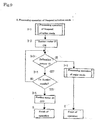
- the equipment is designed for processing operation to select one of three modes; frequent urination mode driving the suction motor when sensed signal of the defecation sensor is absent and the sensed signal is shorter than the time set for the urination sensor, minor mode driving the suction motor when sensed signal of the defecation sensor is absent and the sensed signal is higher than the time set for urination sensor, and major mode driving the suction motor when sensed signal of the defecation sensor is present.
- frequent urination mode driving the suction motor when sensed signal of the defecation sensor is absent and the sensed signal is shorter than the time set for the urination sensor
- minor mode driving the suction motor when sensed signal of the defecation sensor is absent and the sensed signal is higher than the time set for urination sensor
- major mode driving the suction motor when sensed signal of the defecation sensor is present can be conducted appropriately according to kind of excretory substance, amount and size and energy saving can be also done.
- the frequent urination mode is designed to drive the suction motor when short sensed signals at every time set for the urination sensor are less than the number set, so that the rinse solution isn't consumed away.
- the minor mode is designed to drive the suction motor intermittently and clean multiple times when short sensed signals at every time set for the urination sensor are the number set or more, the cleaning becomes surer.
- the major mode drives the suction motor intermittently and cleans the number of times set when sensed signals of the defecation are present, when rinse solution is insufficient, the cleaning is done reduced number of times set. Thus, the cleaning can be done even if the rinse solution becomes insufficient.
- the suction motor is designed to intermittently operate with driving and stopping at a unit of several minutes, the temperature of the suction motor doesn't increase unnecessarily to protect from accidents such as burn and for energy saving.
- the device-house box comprises the sewage-water tank unit, the cleanup processing unit, the suction motor unit, the water supply unit, and the return unit box unit and the napkin cup main body and the device-house box are connected through the hose unit; the rinse solution sent from the water supply pump of said water supply unit is sprayed to the inside of the napkin cup main body; inside the napkin cup main body, the urinary organ and excretory substances are washed and the sewage is vacuumed up by work wind of the suction motor closed and isolated and housed inside said suction motor unit and is divided into the excretory substances and sewage water in said sewage water tank unit; and only said work wind is cleaned up at the cleanup processing unit and returned to said napkin cup main body through the suction motor and return box unit by the suction circulation tube.
- the suction motor and the cooling fan and filter inside the suction motor unit are covered by rigid and vibration-proofing material and installed on a vibration-preventive board made from a vibration-proofing material and held with suspension by vibration-preventive spring, which enables to reduce high noise and vibration produced by the motor and pump used.
- the suction circulation tube is led to the cooling unit installed at the outside of the device house box from the discharge side of the suction motor and the tube is cooled down inside the cooling unit by heat exchange with outer air and then returned to the return box unit, the defect that circulation air is stopped due to excessively heated motor, which is a major disadvantage in conventional equipment, can be prevented by the present invention of a non-motive energy cooling equipment not requiring a special motive energy in which the suction circulation tube passes through the inside of the cooling unit.
- the present invention of the processing equipment of excretory substances has the device-house box 12 comprising the sewage water tank unit 22, cleanup processing unit 23, suction motor unit 24, water supply unit 25, and return box unit 27; in which the napkin cup main body 10 and device-house box 12 are connected by the hose unit 11, rinse solution sent from the water supply pump 39 in said water supply unit 25 is sprayed to the inside of the napkin cup main body 10 to clean the urinary organ and excretory substances in the napkin cup main body 10, the sewage is vacuumed up by work wind of the suction motor 31 closed and isolated inside said suction motor unit 24 and then divided into excretory substances and rinse solution inside said sewage-water tank unit 22 to be housed separately, only said work wind is cleaned up inside the cleanup processing unit 23 and then returned to said napkin cup main body 10 through the suction motor 31 and return box unit 27 by the suction circulation tube 50.
- said suction circulation tube 50 is led to the cooling unit 55 installed outside the said device-house box 12 from the discharge side of said suction motor 31, then cooled down by heat-exchange with outer air inside the cooling unit 55, and returned to said return box unit 27;
- said cleanup processing unit 23,suction motor unit 24, water supply unit 25, and return box unit 27 are housed as individual units inside the device-house box 12 and connected in order and in a detachable manner;
- said sewage water tank unit 22 is separated from said device-house box 12 as a unit and connected to said cleanup processing unit 23 in a detachable manner.
- the concave part receiving excretory substance is mounted at said napkin cup main body and the defecation sensor and urination sensor are mounted at the concave part.
- Said defection sensor installed at the bottom part of stool's falling comprises the sensor to detect stool's hardness for controlling by the control panel unit in order to vacuum up excretory substance at the suction setting with higher suction power for harder stool.
- Said urination sensor comprises two points to control the control panel unit in order to calculate a necessary suction power for vacuuming up excretory substances according to degree of the signals and a sensor to measure the resistance between the two points.
- suction motor 31, cooling fan 32, and filter 33 equipped inside said suction motor unit 24 are covered by highly rigid and vibration proofing material, mounted on the vibration-preventive board processed by vibration-preventive material, and held with suspension by the vibration-preventive spring 79.
- the processing equipment of excretory substances of the present invention is shown as a schematic diagram in Figs. 1 and 2 and as an oblique diagram in Fig.6 .
- the processing equipment of excretory substances of the invention comprises the napkin cup main body 10, device-house box 12, and hose unit 11 connecting these.
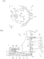
- Said napkin cup main body 10 is shown in Figs.4, 5 , 14 and 15 and is an approximately same as those described in said patent documents 1, 2, and 3. However, in the present invention, an odor sensor 80 as well as the defecation sensor 13, urination sensor 14 is equipped.
- Said napkin cup main body 10 which is applied to a site between crotches of the person receiving care in side lying position via the napkin 54 comprises a bottom plate 71, an anterior plate 72, and a cover 73.
- a sewage discharge hole 74, a return air blowout hole 75a, discharge hole for rinse solution for the pubic site 76a, and a sensor connector 78 are equipped in ascending order from the lower edge of the anterior plate 72.
- the concave part receiving excretory substances 77 is mounted adjacently to said sewage discharge hole 74, and the defecation sensor 13 is mounted at approximate center of the concave part receiving excretory substances 77.
- Multiple urination sensors are equipped at the outer circumference of the defecation sensor 13.
- the odor sensor 80 is mounted at said concave part 77.
- a discharge hole of rinse solution for the anus 76b being adjacent to said discharge hole of rinse solution for the pubis site 76a and a discharge hole of rinse solution for the cup 76c are equipped.
- a return air blowout hole 75b being adjacent to said return air blowout hole 75a is mounted.
- Said defecation sensor 13 comprises a photo-reflector to detect stool's hardness and a distortion sensor or others, being installed at the bottom part of stool's falling, and controls to vacuum up excretory substances by the control panel unit 56 at the setting with higher suction power for higher signals of stool's hardness.
- Said urination sensor 14 has a pair of configuration with two contact points between which the resistance is measured to evaluate for presence or absence of urine and controls by the control panel unit 56 to calculate a necessary suction power according to degree of the signals.
- excretory substances of the invention comprises the napkin cup main body 10, device-house box 12, and hose unit 11 connecting these.
- Said napkin cup main body 10 is shown in Figs.4, 5 , 14 and 15 and is an approximately same as those described in said patent documents 1, 2, and 3. However, in the present invention, an odor sensor 80 as well as the defecation sensor 13, urination sensor 14 is equipped.
- Said napkin cup main body 10 which is applied to a site between crotches of the person receiving care in side lying position via the napkin 54 comprises a bottom plate 71, an anterior plate 72, and a cover 73.
- a sewage discharge hole 74, a return air blowout hole 75a, discharge hole for rinse solution for the pubic site 76a, and a sensor connector 78 are equipped in ascending order from the lower edge of the anterior plate 72.
- the concave part receiving excretory substances 77 is mounted adjacently to said sewage discharge hole 74, and the defecation sensor 13 is mounted at approximate center of the concave part receiving excretory substances 77.
- Multiple urination sensors are equipped at the outer circumference of the defecation sensor 13.
- the odor sensor 80 is mounted at said concave part 77.
- a discharge hole of rinse solution for the anus 76b being adjacent to said discharge hole of rinse solution for the pubis site 76a and a discharge hole of rinse solution for the cup 76c are equipped.
- a return air blowout hole 75b being adjacent to said return air blowout hole 75a is mounted.
- Said defecation sensor 13 comprises a photo-reflector to detect stool's hardness and a distortion sensor or others, being installed at the bottom part of stool's falling, and controls to vacuum up excretory substances by the control panel unit 56 at the setting with higher suction power for higher signals of stool's hardness.
- Said urination sensor 14 has a pair of configuration with two contact points between which the resistance is measured to evaluate for presence or absence of urine and controls by the control panel unit 56 to calculate a necessary suction power according to degree of the signals.
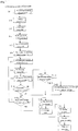
- Said control panel unit 56 comprises a central control unit 81, an input device 82, a counter 83, various sensors 84, a RAM 85, ROM 86, and a drive unit 87, as shown in Fig.7 , and controls various processing modes as shown in Figs. 8-11 .
- Said input device 82 is used for switching to automatic or manual operation, directing various modes, setting or changing the temperature or the flow volume of rinse solution, and other direction, which can be configured by remote control.
- Said various sensor 84 comprises the defecation sensor 13, the urination sensor 14, a temperature sensor 49, a bimetal 57, a water-level sensor 58, a negative pressure sensor 52, a temperature sensor 45, a water-level sensor 41, the odor sensor 80.
- Said counter 83 calculates the number of urination and the number of times of cleaning etc. and memorizes at the RAM85.
- Said RAM 85 memorizes data of the input device 82 or the counter 83 temporarily.
- Said ROM 86 memorizes various control programs for processing as shown in Figs. 8 ⁇ 11 .
- Said drive unit 87 comprises various driving units including the sewage-water tank unit 22, cleanup processing unit 23, suction motor unit 24, water supply unit 25, return air cooler 26, return box unit 27, and heater 44; and drives by output from said central control unit 81.
- the cleaning hole equipped in the napkin cup main body 10 comprises the discharge hole of rinse solution for the anus mounted upward from said the bottom plate 71 and the discharge hole 76b of rinse solution for approximate flat pubic site 76a mounted from the anterior plate 72.
- Said discharge hole 76b is a discharge hole like plus shape (+) and said discharge hole 76a a discharge hole like minus shape (-).
- the direction of water discharge and position in the plus and minus shapes differs between males and females and among races, so that the napkin cup main body 10 can be exchanged according to the physical constitution.
- the bottom plate 71 of the napkin cup main body 10 applied to the region covering from the coccygeal bone to the hip is made from a flexible material for the height and width directions of the person receiving care in order to prevent bed sore.
- the napkin cup main body 10 is made from moderate or high resin such as polyamide series, urethane, polyethylene, polyester, alkid resin etc., is protected by the surface applied by fluorite resin or silicon resin to prevent from sewage, which reduces sewage to attach and to become tainted.
- moderate or high resin such as polyamide series, urethane, polyethylene, polyester, alkid resin etc.
- Said hose unit 11 comprises the sewage suction hose 15, the slight wind hose 16 diverging from the sewage suction hose 15, the return air hose 18 connected to the return air discharge hole 75a, the slight wind hose 17 diverging from the return air hose 18, and the rinse solution hose 20.
- Said hose unit 11 comprises the sewage suction hose 15, the slight wind hose 16 diverging from the sewage suction 15, the return air hose 18 connected to the return air blowout hole 75a, the slight wind hose 17 diverging from the return air hose 18, and the rinse solution hose 20.
- Said sewage suction hose 15 and slight wind hose 16 are connected to said sewage discharge hole 74 and held together as the hose 11a for sewage, and are combined with the sewage water tank unit 22 of the device-house box 12 by the hose connector 63 in a detachable manner.
- the return air hose 18 and slight wind hose 17 connected to said return air blowout hole 75a and the rinse solution hose 20 connected to the discharge hole of rinse solution for the pubic site 76a are held together as the hose for water /air 11b and are combined with the water supply unit 25 of the device house box 12 and the return box unit 27 through the hose connector 64 in a detachable manner.
- Said defecation sensor 13, said urination sensor 14, and 180 lead wires are connected to the control panel unit 56 from the hose connector 64 through the sensor connector 78.
- the nozzles such as those of the sewage suction hose 15 and slight wind hose 16 are designed to have shapes and directions with which water ejected can rotate in relevant hose to clean the inside of the hose.
- the device hose box 12 comprises the sewage water tank 22, cleanup processing unit 23, suction motor unit 24, water supply unit 25, and return box unit 27.
- the cooling mechanism of cooling unit with circulating air 55 and the compactly assembled device house box 12 and easily detachable sewage water tank unit 22 are made improvements.
- Said sewage water tank unit 22 vacuums up and houses excretory substances and sewage water after cleaning by the suction motor 31 of the suction motor unit 24 described later.
- air is vacuumed up from the inside of the sewage water tank 22 through the suction circulation tube 50 and the sewage suction hose 15 by the suction motor 31, excretory substances and sewage water after cleaning in the concave part receiving secretory substances 77 of the napkin cup main body 10 are vacuumed up and housed inside the sewage water tank 22.
- the excretory substances and sewage water after cleaning are separated with gravity by work wind circulating in the suction circulation tube 50.
- the cleanup processing unit 23 connected to the sewage water tank unit 22 equips a mist-eliminating filter 28, an odor-eliminating filter 29, and a disinfect filter 30.
- the negative pressure sensor 52 to detect for if gas tight of hoses connected to the napkin cup main body 10 is mounted at the suction circulation tube 50 inside the cleanup processing unit 23.
- the suction circulation tube 50 and a slight-wind circulation tube 51 mounted along the suction circulation tube 50 pass through the housing of the suction motor unit 24 from the cleanup processing unit 23, connected to the suction motor 31 and led to the cooling box 61 of the cooling unit 55 through the discharge hole 59 from the suction motor unit 24.
- the cooling fan 32 is installed at said suction motor 31. Air taken in from a cooling wind intake hole 34 cools down the suction motor 31 through the filter 33 and is discharged from a cooling wind discharge hole 35.
- the water-level sensor 58 is installed at the sewage water tank unit 22.
- the suction motor 31, cooling fan 32, and filter 33 inside said suction motor unit 24 are covered by highly rigid and vibration proof materials and held with suspension on the vibration preventive board processed by vibration preventive materials such as vibration preventive rubber or by the vibration preventive spring 79.
- the water supply pump 39 is also installed in the same manner.
- Said cooling box 61 which is flat and box-like is placed at the bottom of the main body of the device-house box 12 and this box body and inner partition plate 62 are made from metal plates with good heat conduction.
- the suction circulation tube 50 and slight wind circulation tube 51 which are led to the inside of the cooling box 61 bend as being divided by the partition plates 62 and then led outside from the discharge hole 60.
- materials of metal plates with good heat conduction aluminum extruded materials and aluminum rolled materials which can be processed easily are cheap and suitable for absorption and irradiation as well as coppers are suitable.
- black color made by secondary-electrolyzation coloring increases the heat absorption and heat release more effectively.
- the suction circulation tube 50 and slight wind circulation tube 51 led from said discharge hole 60 is led to the return box unit 27 inside the device house box 12.
- the main tube of the suction circulation tube 50 is connected to the napkin cup main body 10 through the return air hose 18 for about 90% of work wind returning.
- a part of the divergence tubes become the discharge hose 19, which discharges about 10% outside.
- the return box unit 27 equips the temperature sensor 49 and the bimetal 57.
- Said water supply unit 25 equips the rinse solution tank 36, a supplementary tank 37, a hot water tank 38, a water supply pump 39, a valve 46 and a safety tank 40.
- Said hot water tank 38 equips the water-level sensor 42, temperature sensor 43, and heater 44.
- Said safety tank 40 equips the temperature sensor 45.
- the pipe at the discharge side of said valve 46 is connected to the napkin cup main body 10 through said rinse solution hose 20.
- a drainage tube 47 is mounted at said valve 46.
- the control panel unit 56 is mounted in said device house box 12. At the input side of the control panel unit 56, various sensors are connected and drive control signals are transmitted to the output-side suction motor 31, cooling fan 32, water supply pump 39, valve 46, and slight wind motor 48.
- the hot water tank 38 is filled up and if the sewage water tank 22 is empty is confirmed.
- the sign as for the permission for processing operation becomes NO, and the alarm is displayed by signals from the water level sensor 42 or the water level sensor 58 to prevent the automatic operation condition.
- the napkin cup main body 10 is applied to the region from the hip to the groin in the person receiving care via the napkin 54 and the start switch of the control panel unit 56 is turned on.
- sensors or others the water level sensor 41, water level sensor 42, temperature sensor 43, heater 44, temperature sensor 45, temperature sensor 49, negative pressure sensor 52, bimetal 57, water level sensor 58
- the water level sensor 41, water level sensor 42, temperature sensor 43, heater 44, temperature sensor 45, temperature sensor 49, negative pressure sensor 52, bimetal 57, water level sensor 58 become possible condition for processing operation under normal conditions.
- the slight wind motor 48 operates and the slight wind is vacuumed up to the slight wind motor 48 from the napkin cup main body 10 through the slight wind hose 16 and sight wind circulation tube 51, as shown by the dotted lines in Figs 1 and 2 , being then sent from the slight motor 48 through the slight wind hose 17 to the napkin cup main body 10 from the return air blowout holes 75a and 75b.
- the slight wind motor 48 can be operated continuously or intermittently for predetermined time for inhibition of the increase of inner temperature or electricity saving. The details will be explained later, based on Fig.13 .
- Hot water from the discharge hole 76a of rinse solution for the pubic site in the napkin cup main body 10 is sprayed to clean the pubic site and hot water from the discharge hole of rinse solution for the anus 76b is sprayed to clean the anus.
- Hot water from the discharge hole of rinse solution for the cup 76c is sprayed to the concave part receiving excretory substances 77 to wash out the excretory substances.
- the sewage water and excretory substances are led to the discharge hole of sewage 74.
- the suction power of the suction motor 31 is set by the control panel unit 56 according to the values detected by the defecation sensor 13 and urination sensor 14.
- the output of the suction motor 31 ranges 400W - 1kW, which is adjusted to become high, middle, or low level roughly.
- the sewage water tank 22 equips the water level sensor 58 which is a limit sensor of sewage amount.
- the signal is sent to the control panel unit 56 and displayed with alarm on the display board (not shown in the diagram). The alarm is notified to care personnel or nurses by telephone or wireless telephone.
- the sewage water tank 22 separates solid sewage, sewage water, and air.
- the work wind 55 containing water which passed through the sewage water tank unit 22 passes through the cleanup processing unit 23 and is cleaned up.
- the filter box 23 comprises the mist eliminating filter 28, odor eliminating filter 29, and bacteria eliminating filter 30. About 0.3 ⁇ m or larger of particles are eliminated to prevent environmental contamination of surrounding by air's slight discharge and leakage from this equipment.
- the work wind cleaned up is sent to the cooling box 61 in the cooling unit 55 through the suction motor 31.
- the suction motor 31 is cooled down in such a manner that outer air is vacuumed up from the intake hole of cooling wind 34 through the filter 33 by the sewage water tank unit 22 and the air is discharged from the discharge hole of cooling wind 35.
- the cooling down is designed because the suction motor 31 is isolated inside the sewage water tank unit 22 for preventing vibration and noises, so that heat caused by the operation cannot be released anywhere and over-heating of the suction motor 31 may cause operation failure or overheating of work wind flowing through the suction circulation tube 50 may cause burn injury of human body.
- the work wind returns to the napkin cup main body 10 applied to the person receiving care, it is desirable to be kept at about 30 ⁇ 42°C.
- the suction circulation tube 50 and slight wind circulation tube 51 bend in a space are divided off by the partition plate 62, the work wind is cooled down by heat exchange with outer air through the cooling box 61 and partition plate 62 and then discharged from the discharge hole 60.
- Partial air discharged undergoes bacteria elimination and disinfect through a high-performance filter (HEPA filter) or ultraviolet sterilizer.
- HEPA filter high-performance filter
- ultraviolet sterilizer Partial air discharged undergoes bacteria elimination and disinfect through a high-performance filter (HEPA filter) or ultraviolet sterilizer.
- the processing equipment of excretory substances of the present invention comprises the device house box 12, cooling unit 55, sewage water tank unit 22, napkin cup main body 10, and hose unit 11, which are unified in a detachable manner.
- the device house box 12 comprises the cleanup processing unit 23, suction motor unit 24, water supply unit 25, return box unit 27, and control panel unit 56, which are unified in a detachable manner.
- the napkin cup main body 10 and sewage water tank unit 22 are connected by the hose connector 63 through the hose for sewage 11a in the hose unit 11 in a detachable manner.
- the napkin cup main body 10 and the return box unit 27 in the device house box 12 are connected by the hose connector 64 through the hose for water and air 11b in the hose unit 11 in a detachable manner.
- the sewage water tank unit 22 latches together with a locking part 69 on a set board 68 in the cooling unit 55 and is also mounted by a insert hole 67 in a detachable manner, so that the sewage water tank unit 22 is detached from the set board 68 and the hose for sewage 11a of the hose unit 11 is detached by the partition plate 62 to deliver the excretory substances for processing and a cover body 65 is opened by a knob 66 to take out the inner housing container of excretory substances (not shown in figure) and clean with washing out the excretory substances.
- pipes and wires connecting the units are set in an integrated manner and in a one-touch detachable manner, which facilitates to exchange the units such as due to failure or repair.
- the control panel unit 56 enables to wash the hip of the person receiving care by hands and use for washing the pipes of this equipment by rinse solution from the rinse solution hose 20.
- the slight wind motor 48 When the suction motor 31 doesn't operate under an ordinary operation condition in which excretory substances are not detected, the slight wind motor 48 is operating and the return air is sent to the hip and groin part of the person receiving care through the return air hose 18 to dry the region and also dry the pipes of the equipment. That is, the slight wind motor 48 operates and the slight wind circulates through the slight wind hose 16, slight wind circulation tube 51, cooling box 61, and slight wind hose 17 in hose unit 11. Even if the inner temperature of the suction motor 31 cannot be released anywhere to cause overheating of the suction motor 31 when the suction motor 31 stops instantly after its high-speed operation, the above configuration enables to prevent it.
- Air of the slight wind motor 48 inside the return box unit 27 is set in such a manner that the air becomes an appropriate temperature to human body by the bimetal 57 and if the temperature exceeds the appropriate temperature, the slight wind motor 48 rotates inversely to vacuum up the air in the napkin cup main body 10 from the slight wind hose 17 and discharges it outside by the slight wind discharge hose 21.
- a fan as well as the partition plate 62 can be mounted to increase the cooling effect.
- the alarm can be displayed on the control panel unit 56 to notify it to care personnel or nurses.
- Fig. 3 shows characteristic curves of the motor discharge hole, the discharge hole of the cooling unit, and return air hose cup part in the processing equipment of excretory substances of the present invention.
- the solid line indicates the characteristic curve of continuous suction operation for one hour, and the dotted line indicates of intermittent operation with five-minute operation and one-minute stop.
- the temperature of the motor discharge hole 59 increase up to 80°C in the continuous operation and 58 ⁇ 62°C in the intermittent operation.
- the temperature of the discharge hole of the cooling unit 60 increases up to 70°C in the continuous operation and about 50°C in the intermittent operation.
- the temperature felt by human body in the return air hose cup part increases up to 55°C in the continuous operation and 31-35°C in the intermittent operation.
- the motor discharge hole 59 As for the motor discharge hole 59, when the suction motor 31 stops, the temperature without the cooling unit 55 in the continuous operation increases to about 100 °C.
- the equipment of the present invention equips the cooling unit 55, so that the temperature can be suppressed to about 70°C. Actually, the one-hour continuous operation is absent.
- Fig. 12 (a) shows voltage wave shapes when the urination sensor 14 detects the urine.
- the voltage wave shapes are small for a long time.
- control panel unit 56 controls to supply water until an appropriate amount is obtained and vacuum up at a level small.
- Fig. 12 (b) shows wave shapes when the defecation sensor 13 detects soft stool.
- the control panel unit 56 controls to supply water until an appropriate amount is obtained and vacuum up at the level middle.
- the control panel unit 56 controls to supply water until an appropriate amount is obtained and vacuum up at the level middle.
- Fig. 12 (c) shows voltage wave shapes when the defecation sensor 13 detects hard stool. If the voltage is high for a short time and the resistance value of the urination sensor 14 is high, it is considered that urine is absent. In such signal case, the control panel unit 56 controls to supply water until an appropriate amount is obtained and vacuum up at the level high.
- Fig. 12 (d) shows normal voltage wave shapes when usual sewage water detected by the negative pressure sensor 52 inside the cleanup processing unit 23. The suction action is evaluated to be normal and the hip of the person receiving care is dried with slight wind.
- Fig.7(e) shows voltage wave shapes when hard or large amount of stool detected by the negative pressure sensor 52 inside the cleanup processing unit 23 is vacuumed up by ordinary suction power. Those are voltage wave shapes when the suction cannot be done smoothly.
- control panel unit 56 displays the alarm or notify it to care personnel and discharges sewage water by manual work.
- Cooling wind discharge hole 36... Rinse solution tank , 37... Supplementary tank, 38... Hot water tank, 39... Water supply pump, 40... Safety tank, 41...Water level sensor, 42...Water level sensor, 43... Temperature sensor, 44... Heater, 45... Temperature sensor, 46... Valve, 47... Drainage tube, 48... Slight wind motor, 49...Temperature sensor, 50... Suction circulation tube, 51... Slight wind circulation tube, 52... Negative pressure sensor, 53... Drain, 54... Napkin, 55... Cooling unit, 56... Control panel unit, 57... Bimetal, 58... Water level sensor, 59... Discharge hole, 60... Discharge hole, 61... Cooling box, 62... Partition plate, 63... Hose connector, 64...
- Hose connector 65...Cover body, 66... Knob, 67... Insert hole, 68... Set board, 69... Locking part, 70... Caster, 71... Bottom plate, 72... Anterior plate, 73... Cover part, 74... Sewage discharge hole, 75a, 75b... Return air blowout hole, 76a... Discharge hole of rinse solution for the pubic site, 76b... Discharge hole of rinse solution for the anus, 76c... Discharge hole of rinse solution for the cup, 77... Concave part receiving excretory substances, 78... Sensor connector, 79... Vibration preventive spring, 80... Odor sensor, 81... Central control unit (CPU), 82... Input device (remote control), 83... Counter, 84... Various sensors, 85... RAM, 86...ROM, 87...Drive unit
Landscapes
- Health & Medical Sciences (AREA)
- Life Sciences & Earth Sciences (AREA)
- Veterinary Medicine (AREA)
- Public Health (AREA)
- General Health & Medical Sciences (AREA)
- Animal Behavior & Ethology (AREA)
- Epidemiology (AREA)
- Nursing (AREA)
- Orthopedic Medicine & Surgery (AREA)
- Vascular Medicine (AREA)
- Heart & Thoracic Surgery (AREA)
- Biomedical Technology (AREA)
- Engineering & Computer Science (AREA)
- Orthopedics, Nursing, And Contraception (AREA)
- Accommodation For Nursing Or Treatment Tables (AREA)
Claims (9)
- Matériel de traitement de substances excrétoires, comportant une unité à réservoir d'eaux usées (22), une unité de traitement de nettoyage (23), une unité à moteur d'aspiration (24), une unité d'alimentation en eau (25), et une unité à boîte de retour (27) dans une boîte de logement de dispositif (12) reliée à un corps principal en forme de coupelle formant serviette (10) par une unité à tuyau souple (11) ; dans lequel, lors de l'utilisation, une solution de rinçage est envoyée depuis une pompe d'alimentation en eau (39) dans ladite unité d'alimentation en eau (25) et est pulvérisée sur l'intérieur d'un corps principal en forme de coupelle formant serviette (10), dans lequel, lors de l'utilisation, l'organe urinaire et les substances excrétoires sont lavés dans le corps principal en forme de coupelle formant serviette, dans lequel, lors de l'utilisation, les eaux usées sont aspirées par un flux d'air de travail d'un moteur d'aspiration (31) fermé et isolé à l'intérieur de ladite unité à moteur d'aspiration (24), dans lequel, lors de l'utilisation, les eaux usées sont divisées en substances excrétoires et la solution de rinçage et logées séparément dans ladite unité à réservoir d'eaux usées (22) et, dans lequel, lors de l'utilisation, seul ledit flux d'air de travail est nettoyé dans l'unité de traitement de nettoyage (23) et retourné au corps principal en forme de coupelle formant serviette (10) par le moteur d'aspiration (31) et l'unité à boîte de retour (27) par un tube de circulation d'aspiration (50) ; dans lequel ladite unité de traitement de nettoyage (23), l'unité à moteur d'aspiration (24), l'unité d'alimentation en eau (25), et l'unité à boîte de retour (27) sont fabriquées en tant qu'unités indépendantes et logées à l'intérieur de la boîte de logement de dispositif (12) et reliées aussi dans l'ordre de manière détachable ; caractérisé en ce que, lors de l'utilisation, ledit tube de circulation d'aspiration (50) est dirigé vers une unité de refroidissement (55) montée à l'extérieur de ladite boîte de logement de dispositif (12) depuis le côté d'évacuation dudit moteur d'aspiration (31), est refroidi par échange de chaleur avec l'air extérieur à l'intérieur de l'unité de refroidissement (55), et retourné ensuite vers ladite unité à boîte de retour (27) ; et ladite unité à réservoir d'eaux usées (22) est séparée de ladite boîte de logement de dispositif (12), fabriquée en tant qu'unité, et reliée à ladite unité de traitement de nettoyage (23) de manière détachable.
- Matériel de traitement de substances excrétoires selon la revendication 1, l'aménagement de l'unité de refroidissement (55) comportant une boîte de refroidissement de type boîte (61) semblable à une boîte métallique conductrice de chaleur dans laquelle le tube de circulation d'aspiration (50) courbé est agencé.
- Matériel de traitement de substances excrétoires selon la revendication 1 ou 2, dans lequel un tube de circulation de brise (51) est monté le long du tube de circulation d'aspiration (50) circulant du corps principal en forme de coupelle formant serviette (10) au corps principal en forme de coupelle formant serviette (10) à travers l'unité à réservoir d'eaux usées (22), l'unité de traitement de nettoyage (23), l'unité de refroidissement (55), et l'unité à boîte de retour (27), et un moteur de brise (48), par lequel la brise destinée au séchage circule lorsque le moteur d'aspiration (31) ne fonctionne pas, est monté au niveau du tube de circulation de brise (51) à l'intérieur de ladite unité à boîte de retour (27).
- Matériel de traitement de substances excrétoires selon la revendication 3, pourvu d'ailettes multiples conductrices de l'échange de chaleur avec l'air extérieur destiné au tube de circulation d'aspiration (50) et au tube de circulation de brise (51) à l'intérieur de la boîte de refroidissement (61).
- Matériel de traitement de substances excrétoires selon les revendications 1, 2, 3 ou 4, dans lequel un tuyau souple d'évacuation partielle (19) est relié au tube de circulation d'aspiration (50) pour évacuer une partie du flux d'air de travail qui circule et le même volume d'air que celui évacué est aspiré de l'extérieur au niveau du corps principal en forme de coupelle formant serviette (10).
- Matériel de traitement de substances excrétoires selon les revendications 2, 3, 4 ou 5, pourvu d'une boîte de refroidissement plate de type boîte (61) doublée d'un siège sur lequel la boîte de logement de dispositif (12) et l'unité à réservoir d'eaux usées (22) sont placées et dont la roulette (70) est montée au niveau de la face inférieure.
- Matériel de traitement de substances excrétoires selon la revendication 3, pourvu du bimétal (57) aménagé à l'intérieur de l'unité à boîte de retour (27), par lequel lorsque de l'air circulant par le moteur de brise (48) dépasse une température appropriée pour le corps humain fixée d'avance, le moteur de brise (48) tourne de manière inverse pour aspirer l'air chauffé dans le corps principal en forme de coupelle formant serviette (10) provenant du tuyau souple de brise (17) et l'évacuer ensuite à l'extérieur au niveau du tuyau souple d'évacuation de brise (21).
- Matériel de traitement de substances excrétoires selon la revendication 1, pourvu d'un capteur de pression négative (52) aménagé dans l'unité de traitement de nettoyage (23) pour détecter si l'étanchéité à l'air des tuyaux souples reliés au corps principal en forme de coupelle formant serviette (10) est maintenue.
- Matériel de traitement de substances excrétoires selon la revendication 1, pourvu de l'unité d'alimentation en eau (25) comportant un réservoir de solution de rinçage (36), un réservoir supplémentaire (37), une pompe d'alimentation en eau (39), un réservoir d'eau chaude (38), une soupape (46), et un réservoir de sécurité (40) ; dans lequel un capteur de niveau d'eau (41) est installé au niveau dudit réservoir supplémentaire (37), un capteur de niveau d'eau (41), un capteur de température (43), et un dispositif de chauffage pour produire de l'eau chaude (44) sont installés au niveau dudit réservoir d'eau chaude (38), et un capteur de température (45) est installé au niveau dudit réservoir de sécurité (40).
Priority Applications (2)
| Application Number | Priority Date | Filing Date | Title |
|---|---|---|---|
| EP20140170075 EP2796116A1 (fr) | 2012-04-02 | 2012-04-02 | Équipement de traitement de substances excrétoires et procédé |
| EP20140170074 EP2796115A1 (fr) | 2012-04-02 | 2012-04-02 | Équipement de traitement de substances excrétoires et procédé |
Applications Claiming Priority (1)
| Application Number | Priority Date | Filing Date | Title |
|---|---|---|---|
| PCT/JP2012/058950 WO2013150588A1 (fr) | 2012-04-02 | 2012-04-02 | Dispositif de manipulation des excréments et procédé associé |
Related Child Applications (4)
| Application Number | Title | Priority Date | Filing Date |
|---|---|---|---|
| EP20140170074 Division EP2796115A1 (fr) | 2012-04-02 | 2012-04-02 | Équipement de traitement de substances excrétoires et procédé |
| EP20140170074 Division-Into EP2796115A1 (fr) | 2012-04-02 | 2012-04-02 | Équipement de traitement de substances excrétoires et procédé |
| EP20140170075 Division EP2796116A1 (fr) | 2012-04-02 | 2012-04-02 | Équipement de traitement de substances excrétoires et procédé |
| EP20140170075 Division-Into EP2796116A1 (fr) | 2012-04-02 | 2012-04-02 | Équipement de traitement de substances excrétoires et procédé |
Publications (3)
| Publication Number | Publication Date |
|---|---|
| EP2676643A1 EP2676643A1 (fr) | 2013-12-25 |
| EP2676643A4 EP2676643A4 (fr) | 2015-05-06 |
| EP2676643B1 true EP2676643B1 (fr) | 2018-03-07 |
Family
ID=49052907
Family Applications (3)
| Application Number | Title | Priority Date | Filing Date |
|---|---|---|---|
| EP20140170075 Withdrawn EP2796116A1 (fr) | 2012-04-02 | 2012-04-02 | Équipement de traitement de substances excrétoires et procédé |
| EP20140170074 Withdrawn EP2796115A1 (fr) | 2012-04-02 | 2012-04-02 | Équipement de traitement de substances excrétoires et procédé |
| EP12832728.5A Not-in-force EP2676643B1 (fr) | 2012-04-02 | 2012-04-02 | Dispositif de manipulation des excréments |
Family Applications Before (2)
| Application Number | Title | Priority Date | Filing Date |
|---|---|---|---|
| EP20140170075 Withdrawn EP2796116A1 (fr) | 2012-04-02 | 2012-04-02 | Équipement de traitement de substances excrétoires et procédé |
| EP20140170074 Withdrawn EP2796115A1 (fr) | 2012-04-02 | 2012-04-02 | Équipement de traitement de substances excrétoires et procédé |
Country Status (8)
| Country | Link |
|---|---|
| US (1) | US9585805B2 (fr) |
| EP (3) | EP2796116A1 (fr) |
| JP (1) | JP5254498B1 (fr) |
| KR (3) | KR101524030B1 (fr) |
| CN (1) | CN104334127B (fr) |
| SG (1) | SG11201406219RA (fr) |
| TW (3) | TW201350101A (fr) |
| WO (1) | WO2013150588A1 (fr) |
Cited By (1)
| Publication number | Priority date | Publication date | Assignee | Title |
|---|---|---|---|---|
| EP3838234B1 (fr) * | 2019-12-18 | 2023-05-24 | Curaco, Inc. | Robot de soins des excréments avec fonction intégrée d'analyse du mouvement et de l'état du patient alité |
Families Citing this family (82)
| Publication number | Priority date | Publication date | Assignee | Title |
|---|---|---|---|---|
| JP5649093B1 (ja) * | 2014-01-20 | 2015-01-07 | 恵子 齋藤 | 装着用便座 |
| US10390989B2 (en) | 2014-03-19 | 2019-08-27 | Purewick Corporation | Apparatus and methods for receiving discharged urine |
| US11806266B2 (en) | 2014-03-19 | 2023-11-07 | Purewick Corporation | Apparatus and methods for receiving discharged urine |
| US10226376B2 (en) | 2014-03-19 | 2019-03-12 | Purewick Corporation | Apparatus and methods for receiving discharged urine |
| US11376152B2 (en) | 2014-03-19 | 2022-07-05 | Purewick Corporation | Apparatus and methods for receiving discharged urine |
| US10952889B2 (en) | 2016-06-02 | 2021-03-23 | Purewick Corporation | Using wicking material to collect liquid for transport |
| CN203885767U (zh) * | 2014-04-04 | 2014-10-22 | 苏州欧圣电气工业有限公司 | 一种护理机快速连接结构 |
| KR101633488B1 (ko) * | 2014-08-18 | 2016-06-24 | 주식회사 엔젤윙즈 | 자동 배변 처리장치 및 이를 이용한 배변량 측정 방법 |
| TWI551254B (zh) * | 2014-08-29 | 2016-10-01 | Jin-Tian Huang | Chair |
| CN104398334B (zh) * | 2014-09-10 | 2017-01-11 | 东莞市圆葱医疗器械有限公司 | 一种大小便自动处理设备的便器 |
| US10358807B2 (en) * | 2014-11-25 | 2019-07-23 | Shandong Crrc Huateng Environment Co., Ltd. | Suction seat for intelligent nursing toilet bowl |
| WO2016123863A1 (fr) * | 2015-02-04 | 2016-08-11 | 浙江新丰医疗器械有限公司 | Dispositif de recueil de déchets corporels pour machine de soins automatique |
| CN105708646B (zh) * | 2015-12-24 | 2018-09-11 | 美的集团股份有限公司 | 护理机及其的电机控制方法 |
| CN105434128B (zh) * | 2016-01-09 | 2018-05-04 | 乐清市君康智能科技有限公司 | 高效人体智能护理仪 |
| US10973678B2 (en) | 2016-07-27 | 2021-04-13 | Purewick Corporation | Apparatus and methods for receiving discharged urine |
| US10376406B2 (en) | 2016-07-27 | 2019-08-13 | Purewick Corporation | Male urine collection device using wicking material |
| CN106618911A (zh) * | 2017-01-17 | 2017-05-10 | 上海正邻机电自动化设备有限公司 | 一种带有自动清洁的医用尿盆 |
| CN110582219B (zh) * | 2017-01-25 | 2022-06-07 | 株式会社促进 | 排泄物处理方法及其装置 |
| WO2018144463A1 (fr) | 2017-01-31 | 2018-08-09 | Purewick Corporation | Appareil et procédés pour la réception d'urine excrétée |
| JP6803313B2 (ja) * | 2017-09-13 | 2020-12-23 | 行雄 阿部 | 介護用排泄物処理装置 |
| AU2019262939A1 (en) | 2018-05-01 | 2020-11-26 | Purewick Corporation | Fluid collection devices, systems, and methods |
| JP7072084B2 (ja) | 2018-05-01 | 2022-05-19 | ピュアウィック コーポレイション | 流体収集装置、関連システム、及び関連方法 |
| EP3787571B1 (fr) | 2018-05-01 | 2022-06-01 | Purewick Corporation | Vêtements de collecte de fluide |
| US11944740B2 (en) | 2018-05-01 | 2024-04-02 | Purewick Corporation | Fluid collection devices, related systems, and related methods |
| AU2019262945B2 (en) | 2018-05-01 | 2022-08-25 | Purewick Corporation | Fluid collection devices and methods of using the same |
| EP3787569B1 (fr) | 2018-05-01 | 2025-07-16 | Purewick Corporation | Dispositifs et systèmes de collecte de fluide |
| CN112839555B (zh) * | 2018-10-09 | 2023-02-03 | 株式会社促进 | 排泄物处理方法及其装置 |
| CN109567998B (zh) * | 2018-11-08 | 2024-09-06 | 苏州欧圣电气股份有限公司 | 一种护理机及其护理机主机 |
| CN109528381B (zh) * | 2018-11-08 | 2024-09-03 | 苏州欧圣电气股份有限公司 | 护理机 |
| CN109773659B (zh) * | 2019-02-25 | 2020-07-10 | 华中科技大学 | 一种防过载智能力控磨抛装置及磨抛机器人 |
| CA3143904C (fr) | 2019-06-21 | 2023-11-28 | Purewick Corporation | Dispositifs de collecte de fluide comprenant une zone de fixation de base, et systemes et procedes associes |
| JP6635456B1 (ja) * | 2019-06-28 | 2020-01-22 | 株式会社リバティソリューション | 自動排泄処理装置及び建物 |
| ES2961269T3 (es) | 2019-07-11 | 2024-03-11 | Purewick Corp | Dispositivos y sistemas de recogida de líquido |
| WO2021016026A1 (fr) | 2019-07-19 | 2021-01-28 | Purewick Corporation | Dispositifs de collecte de fluide comprenant au moins un matériau à mémoire de forme |
| CN110575335B (zh) * | 2019-09-27 | 2020-12-01 | 河南省中医院(河南中医药大学第二附属医院) | 一种临床内科护理用床侧护理装置 |
| EP4051190B1 (fr) | 2019-10-28 | 2024-05-22 | Purewick Corporation | Ensembles de collecte de fluide comprenant un orifice d'échantillon |
| EP4559443A3 (fr) | 2020-01-03 | 2025-06-18 | Purewick Corporation | Dispositifs de collecte d'urine ayant une partie relativement large et une partie allongée et procédés associés |
| WO2021188817A1 (fr) | 2020-03-19 | 2021-09-23 | Purewick Corporation | Ensembles de collecte de fluide comprenant un ou plusieurs éléments d'amélioration du mouvement |
| US12521288B2 (en) | 2020-03-26 | 2026-01-13 | Purewick Corporation | Multi-layer urine capture device and related methods |
| WO2021207621A1 (fr) | 2020-04-10 | 2021-10-14 | Purewick Corporation | Ensembles de collecte de fluide comprenant un ou plusieurs éléments de prévention de fuite |
| US12465514B2 (en) | 2020-04-17 | 2025-11-11 | Purewick Corporation | Fluid collection devices, systems, and methods securing a protruding portion in position for use |
| WO2021211801A1 (fr) | 2020-04-17 | 2021-10-21 | Purewick Corporation | Ensembles de collecte de fluide comprenant une barrière imperméable aux fluides comportant une cuvette et une base |
| US12472090B2 (en) | 2020-04-17 | 2025-11-18 | Purewick Corporation | Female external catheter devices having a urethral cup, and related systems and methods |
| US12491104B2 (en) | 2020-04-20 | 2025-12-09 | Purewick Corporation | Fluid collection devices adjustable between a vacuum-based orientation and a gravity-based orientation, and related systems and methods |
| US12048643B2 (en) | 2020-05-27 | 2024-07-30 | Purewick Corporation | Fluid collection assemblies including at least one inflation device and methods and systems of using the same |
| CN111631878B (zh) * | 2020-07-06 | 2021-06-25 | 张宏岩 | 一种适用于骨折卧床病人的粪便检测床 |
| USD967409S1 (en) | 2020-07-15 | 2022-10-18 | Purewick Corporation | Urine collection apparatus cover |
| US12440371B2 (en) | 2020-08-06 | 2025-10-14 | Purewick Corporation | Fluid collection system including a garment and a fluid collection device |
| US12350187B2 (en) | 2020-08-11 | 2025-07-08 | Purewick Corporation | Fluid collection assemblies defining waist and leg openings |
| EP4210643A1 (fr) | 2020-09-09 | 2023-07-19 | Purewick Corporation | Dispositifs, systèmes et procédés de collecte de fluide |
| US11801186B2 (en) | 2020-09-10 | 2023-10-31 | Purewick Corporation | Urine storage container handle and lid accessories |
| US12156792B2 (en) | 2020-09-10 | 2024-12-03 | Purewick Corporation | Fluid collection assemblies including at least one inflation device |
| EP4225229A2 (fr) * | 2020-10-07 | 2023-08-16 | Purewick Corporation | Ensembles, systèmes et procédés de transfert de fluide |
| US12042423B2 (en) | 2020-10-07 | 2024-07-23 | Purewick Corporation | Fluid collection systems including at least one tensioning element |
| US12569365B2 (en) | 2020-10-21 | 2026-03-10 | Purewick Corporation | Fluid collection assemblies including at least one shape memory material disposed in the conduit |
| US12440370B2 (en) | 2020-10-21 | 2025-10-14 | Purewick Corporation | Apparatus with compressible casing for receiving discharged urine |
| US12257174B2 (en) | 2020-10-21 | 2025-03-25 | Purewick Corporation | Fluid collection assemblies including at least one of a protrusion or at least one expandable material |
| US12208031B2 (en) | 2020-10-21 | 2025-01-28 | Purewick Corporation | Adapters for fluid collection devices |
| US12048644B2 (en) | 2020-11-03 | 2024-07-30 | Purewick Corporation | Apparatus for receiving discharged urine |
| US12070432B2 (en) | 2020-11-11 | 2024-08-27 | Purewick Corporation | Urine collection system including a flow meter and related methods |
| US12245967B2 (en) | 2020-11-18 | 2025-03-11 | Purewick Corporation | Fluid collection assemblies including an adjustable spine |
| US12599495B2 (en) | 2021-01-05 | 2026-04-14 | Purewick Corporation | Male external catheter with attachment interface configured to bias against penis |
| US12268627B2 (en) | 2021-01-06 | 2025-04-08 | Purewick Corporation | Fluid collection assemblies including at least one securement body |
| JP2024503636A (ja) | 2021-01-07 | 2024-01-26 | ピュアウィック コーポレイション | 車椅子に固定可能な尿収集システムおよび関連する方法 |
| US20240058520A1 (en) * | 2021-01-07 | 2024-02-22 | Purewick Corporation | Wheelchair securable urine collection systems and related methods |
| EP4349306A3 (fr) | 2021-01-19 | 2024-06-05 | Purewick Corporation | Dispositifs, systèmes et procédés de collecte de fluide à ajustement variable |
| JP7725045B2 (ja) | 2021-02-01 | 2025-08-19 | 株式会社リバティソリューション | 自動排泄処理装置 |
| US12178735B2 (en) | 2021-02-09 | 2024-12-31 | Purewick Corporation | Noise reduction for a urine suction system |
| EP4274524B1 (fr) | 2021-02-26 | 2024-08-28 | Purewick Corporation | Dispositif de collecte de fluide configuré comme un dispositif de collecte d'urine masculin |
| US12551385B2 (en) | 2021-03-05 | 2026-02-17 | Purewick Corporation | Fluid collection assembly including a tube having porous wicking material for improved fluid transport |
| US12558472B2 (en) | 2021-03-05 | 2026-02-24 | Purewick Corporation | Portable fluid collection systems with storage and related methods |
| US12458525B2 (en) | 2021-03-10 | 2025-11-04 | Purewick Corporation | Acoustic silencer for a urine suction system |
| CN112856671B (zh) * | 2021-03-23 | 2024-12-20 | 西安建筑科技大学 | 一种病房送排风空气幕系统及其使用方法 |
| US12029677B2 (en) | 2021-04-06 | 2024-07-09 | Purewick Corporation | Fluid collection devices having a collection bag, and related systems and methods |
| US12233003B2 (en) | 2021-04-29 | 2025-02-25 | Purewick Corporation | Fluid collection assemblies including at least one length adjusting feature |
| US12251333B2 (en) | 2021-05-21 | 2025-03-18 | Purewick Corporation | Fluid collection assemblies including at least one inflation device and methods and systems of using the same |
| US12324767B2 (en) | 2021-05-24 | 2025-06-10 | Purewick Corporation | Fluid collection assembly including a customizable external support and related methods |
| US12150885B2 (en) | 2021-05-26 | 2024-11-26 | Purewick Corporation | Fluid collection system including a cleaning system and methods |
| US12575960B2 (en) | 2021-06-24 | 2026-03-17 | Purewick Corporation | Urine collection systems having one or more of volume, pressure, or flow indicators, and related methods |
| US12551366B2 (en) | 2021-08-02 | 2026-02-17 | Purewick Corporation | Fluid collection devices having multiple fluid collection regions, and related systems and methods |
| US12594062B2 (en) | 2021-09-08 | 2026-04-07 | Purewick Corporation | Fluid collection assemblies including an extension |
| US20250302685A1 (en) * | 2023-07-25 | 2025-10-02 | Sebastian J. Heredia | Human waste capturing device |
Family Cites Families (30)
| Publication number | Priority date | Publication date | Assignee | Title |
|---|---|---|---|---|
| US4973256A (en) | 1989-08-18 | 1990-11-27 | Texas Instruments Incorporated | Device under test interface board and test electronic card interconnection in semiconductor test system |
| JP3493244B2 (ja) * | 1995-04-10 | 2004-02-03 | 株式会社東洋商社 | 金型の水管路用簡易洗浄システム |
| JPH1147180A (ja) | 1997-07-29 | 1999-02-23 | Niles Parts Co Ltd | 排泄物処理装置 |
| JP2001112802A (ja) * | 1999-10-18 | 2001-04-24 | Niles Parts Co Ltd | 排泄物処理装置 |
| CA2350276A1 (fr) * | 2000-06-12 | 2001-12-12 | Lembit Maimets | Appareil et technique pour soigner et nettoyer les patients |
| JP2002113030A (ja) * | 2000-10-10 | 2002-04-16 | Niles Parts Co Ltd | 排泄物処理装置 |
| JP3476803B2 (ja) | 2000-11-20 | 2003-12-10 | 株式会社アルボ | 排泄物処理装置 |
| EP1435512A1 (fr) | 2001-09-04 | 2004-07-07 | Alubo Co., Ltd. | Capteur couple a une capacite et procede de detection d'une substance au moyen du capteur couple a une capacite |
| JP4209142B2 (ja) * | 2002-06-19 | 2009-01-14 | 野村マイクロ・サイエンス株式会社 | 処理装置 |
| JP2005177423A (ja) * | 2003-12-19 | 2005-07-07 | Masahiko Okuno | 電動屎瓶および陰部に装着可能な集尿アタッチメント |
| JP4542476B2 (ja) * | 2004-10-20 | 2010-09-15 | 株式会社日立製作所 | 自動収尿装置 |
| JPWO2006046532A1 (ja) * | 2004-10-29 | 2008-05-22 | 学 伊勢 | 排泄物処理装置 |
| JP2006141590A (ja) | 2004-11-18 | 2006-06-08 | Enuwikku:Kk | 自動排泄処理装置および穴明きおむつ |
| EP1873318A4 (fr) * | 2005-04-11 | 2009-05-06 | Zhenhua Liu | Dispositif de traitement automatique des rejets humains |
| JP2007312920A (ja) * | 2006-05-24 | 2007-12-06 | Care Life Japan Kk | 自動排泄処理装置及び自動排泄処理方法 |
| JP4116652B2 (ja) * | 2006-07-04 | 2008-07-09 | 中村 稔 | 自動排便処理装置 |
| US20080017377A1 (en) * | 2006-07-19 | 2008-01-24 | Cowan Kenneth M | Well fluid formulation and method |
| JP4065002B2 (ja) * | 2006-07-31 | 2008-03-19 | 中村 稔 | 自動排便処理装置 |
| CN101396319A (zh) * | 2007-09-20 | 2009-04-01 | 株式会社哈德福禄 | 排泄物处理装置 |
| JP2009188505A (ja) | 2008-02-04 | 2009-08-20 | Sharp Corp | 画像形成装置 |
| JP4520510B2 (ja) * | 2008-02-05 | 2010-08-04 | 稔 中村 | 人体仰臥用便器 |
| JP4567757B2 (ja) * | 2008-02-05 | 2010-10-20 | 稔 中村 | 自動排尿便処理装置 |
| JP4243643B1 (ja) * | 2008-03-31 | 2009-03-25 | 株式会社日立製作所 | 排泄物処理装置 |
| JP3144371U (ja) | 2008-05-27 | 2008-08-28 | 徳雄 齋藤 | 自動排泄処理装置 |
| US8361043B2 (en) * | 2009-01-07 | 2013-01-29 | Spiracur Inc. | Reduced pressure therapy of the sacral region |
| JP5356838B2 (ja) * | 2009-01-20 | 2013-12-04 | 株式会社日立製作所 | 自動収尿装置 |
| WO2010128813A2 (fr) * | 2009-05-07 | 2010-11-11 | 주식회사 큐라코 | Appareil et procédé de traitement des excreta |
| JP5210264B2 (ja) | 2009-05-12 | 2013-06-12 | 徳雄 齋藤 | 生体情報を収集し伝達する装置 |
| US8904571B2 (en) * | 2009-08-06 | 2014-12-09 | Jeffrey O. Moore | Fresh flush recycling toilet |
| CN101836913A (zh) * | 2010-04-29 | 2010-09-22 | 杭州亿脑智能科技有限公司 | 自动护理装置 |
-
2012
- 2012-04-02 JP JP2012526778A patent/JP5254498B1/ja not_active Expired - Fee Related
- 2012-04-02 EP EP20140170075 patent/EP2796116A1/fr not_active Withdrawn
- 2012-04-02 EP EP20140170074 patent/EP2796115A1/fr not_active Withdrawn
- 2012-04-02 KR KR1020137020835A patent/KR101524030B1/ko not_active Expired - Fee Related
- 2012-04-02 KR KR1020147032352A patent/KR101642482B1/ko not_active Expired - Fee Related
- 2012-04-02 KR KR1020147032353A patent/KR101639069B1/ko not_active Expired - Fee Related
- 2012-04-02 US US14/389,558 patent/US9585805B2/en not_active Expired - Fee Related
- 2012-04-02 CN CN201280073500.7A patent/CN104334127B/zh not_active Expired - Fee Related
- 2012-04-02 EP EP12832728.5A patent/EP2676643B1/fr not_active Not-in-force
- 2012-04-02 SG SG11201406219RA patent/SG11201406219RA/en unknown
- 2012-04-02 WO PCT/JP2012/058950 patent/WO2013150588A1/fr not_active Ceased
-
2013
- 2013-02-22 TW TW102106136A patent/TW201350101A/zh unknown
- 2013-02-22 TW TW103131721A patent/TWI558390B/zh not_active IP Right Cessation
- 2013-02-22 TW TW103131720A patent/TWI558389B/zh not_active IP Right Cessation
Non-Patent Citations (1)
| Title |
|---|
| None * |
Cited By (1)
| Publication number | Priority date | Publication date | Assignee | Title |
|---|---|---|---|---|
| EP3838234B1 (fr) * | 2019-12-18 | 2023-05-24 | Curaco, Inc. | Robot de soins des excréments avec fonction intégrée d'analyse du mouvement et de l'état du patient alité |
Also Published As
| Publication number | Publication date |
|---|---|
| KR20130140136A (ko) | 2013-12-23 |
| EP2796115A1 (fr) | 2014-10-29 |
| KR101524030B1 (ko) | 2015-05-29 |
| US9585805B2 (en) | 2017-03-07 |
| TWI558389B (zh) | 2016-11-21 |
| KR20140139632A (ko) | 2014-12-05 |
| KR101639069B1 (ko) | 2016-07-13 |
| KR101642482B1 (ko) | 2016-07-25 |
| WO2013150588A1 (fr) | 2013-10-10 |
| EP2796116A1 (fr) | 2014-10-29 |
| TW201446232A (zh) | 2014-12-16 |
| JPWO2013150588A1 (ja) | 2015-12-14 |
| KR20140139633A (ko) | 2014-12-05 |
| TWI558390B (zh) | 2016-11-21 |
| TW201350101A (zh) | 2013-12-16 |
| JP5254498B1 (ja) | 2013-08-07 |
| SG11201406219RA (en) | 2014-11-27 |
| EP2676643A1 (fr) | 2013-12-25 |
| CN104334127B (zh) | 2016-06-08 |
| HK1205921A1 (en) | 2015-12-31 |
| US20150328072A1 (en) | 2015-11-19 |
| CN104334127A (zh) | 2015-02-04 |
| TW201446233A (zh) | 2014-12-16 |
| EP2676643A4 (fr) | 2015-05-06 |
Similar Documents
| Publication | Publication Date | Title |
|---|---|---|
| EP2676643B1 (fr) | Dispositif de manipulation des excréments | |
| US20030181880A1 (en) | Self cleaning garment with portable cleaning apparatus suitable for incontinent individuals and the like | |
| RU130843U1 (ru) | Автоматический очиститель фекалий без раздевания и одевания | |
| KR101015717B1 (ko) | 배설물 자동처리장치 | |
| KR102236558B1 (ko) | 자동 집뇨장치 | |
| CN106510929B (zh) | 一种大小便智能护理系统 | |
| JP5362897B2 (ja) | 排泄物処理装置及びその方法 | |
| KR20110080012A (ko) | 배설물 자동처리장치 | |
| JP5368621B2 (ja) | 排泄物処理装置 | |
| CN104720955B (zh) | 排泄物处理装置及其方法 | |
| CN104688403A (zh) | 排泄物处理装置及其方法 | |
| JP2008036018A (ja) | 使用者装着装置及び自動排泄処理装置 | |
| CN215875164U (zh) | 一种男性大小便失禁引流装置 | |
| CN211382098U (zh) | 妇产科护理用接尿装置 | |
| KR100795149B1 (ko) | 자동 배설물 처리장치 | |
| KR100829524B1 (ko) | 자동 배변 처리장치 | |
| CN113081452A (zh) | 一种男性大小便失禁引流装置 | |
| HK1205921B (en) | Excreta-handling device and method therefor | |
| JP2008035988A (ja) | 使用者装着装置及び自動排泄処理装置 | |
| JP2008036301A (ja) | 使用者装着装置及び自動排泄処理装置 | |
| JP2004313246A (ja) | 排泄物処理システムおよび排泄物処理装置 | |
| KR20190092186A (ko) | 자동 대소변 채집장치 | |
| WO1997043986A1 (fr) | Appareil sanitaire de soins pour l'enlevement par lavage et l'aspiration automatique d'excrements |
Legal Events
| Date | Code | Title | Description |
|---|---|---|---|
| PUAI | Public reference made under article 153(3) epc to a published international application that has entered the european phase |
Free format text: ORIGINAL CODE: 0009012 |
|
| 17P | Request for examination filed |
Effective date: 20130325 |
|
| AK | Designated contracting states |
Kind code of ref document: A1 Designated state(s): AL AT BE BG CH CY CZ DE DK EE ES FI FR GB GR HR HU IE IS IT LI LT LU LV MC MK MT NL NO PL PT RO RS SE SI SK SM TR |
|
| RIC1 | Information provided on ipc code assigned before grant |
Ipc: A61F 5/451 20060101AFI20141209BHEP |
|
| RA4 | Supplementary search report drawn up and despatched (corrected) |
Effective date: 20150410 |
|
| RIC1 | Information provided on ipc code assigned before grant |
Ipc: A61F 5/451 20060101AFI20150405BHEP |
|
| RIN1 | Information on inventor provided before grant (corrected) |
Inventor name: KOMATSU, KIICHI Inventor name: AKOSHIMA, FUMIYUKI Inventor name: KUROSAWA, NOBUYOSHI Inventor name: SAITOH, TOKUO |
|
| DAX | Request for extension of the european patent (deleted) | ||
| 17Q | First examination report despatched |
Effective date: 20170616 |
|
| GRAP | Despatch of communication of intention to grant a patent |
Free format text: ORIGINAL CODE: EPIDOSNIGR1 |
|
| INTG | Intention to grant announced |
Effective date: 20170918 |
|
| GRAS | Grant fee paid |
Free format text: ORIGINAL CODE: EPIDOSNIGR3 |
|
| GRAA | (expected) grant |
Free format text: ORIGINAL CODE: 0009210 |
|
| AK | Designated contracting states |
Kind code of ref document: B1 Designated state(s): AL AT BE BG CH CY CZ DE DK EE ES FI FR GB GR HR HU IE IS IT LI LT LU LV MC MK MT NL NO PL PT RO RS SE SI SK SM TR |
|
| REG | Reference to a national code |
Ref country code: GB Ref legal event code: FG4D |
|
| REG | Reference to a national code |
Ref country code: CH Ref legal event code: EP Ref country code: AT Ref legal event code: REF Ref document number: 975747 Country of ref document: AT Kind code of ref document: T Effective date: 20180315 |
|
| REG | Reference to a national code |
Ref country code: DE Ref legal event code: R096 Ref document number: 602012043836 Country of ref document: DE |
|
| REG | Reference to a national code |
Ref country code: IE Ref legal event code: FG4D |
|
| REG | Reference to a national code |
Ref country code: FR Ref legal event code: PLFP Year of fee payment: 7 |
|
| REG | Reference to a national code |
Ref country code: NL Ref legal event code: MP Effective date: 20180307 |
|
| REG | Reference to a national code |
Ref country code: LT Ref legal event code: MG4D |
|
| PG25 | Lapsed in a contracting state [announced via postgrant information from national office to epo] |
Ref country code: FI Free format text: LAPSE BECAUSE OF FAILURE TO SUBMIT A TRANSLATION OF THE DESCRIPTION OR TO PAY THE FEE WITHIN THE PRESCRIBED TIME-LIMIT Effective date: 20180307 Ref country code: HR Free format text: LAPSE BECAUSE OF FAILURE TO SUBMIT A TRANSLATION OF THE DESCRIPTION OR TO PAY THE FEE WITHIN THE PRESCRIBED TIME-LIMIT Effective date: 20180307 Ref country code: NO Free format text: LAPSE BECAUSE OF FAILURE TO SUBMIT A TRANSLATION OF THE DESCRIPTION OR TO PAY THE FEE WITHIN THE PRESCRIBED TIME-LIMIT Effective date: 20180607 Ref country code: ES Free format text: LAPSE BECAUSE OF FAILURE TO SUBMIT A TRANSLATION OF THE DESCRIPTION OR TO PAY THE FEE WITHIN THE PRESCRIBED TIME-LIMIT Effective date: 20180307 Ref country code: LT Free format text: LAPSE BECAUSE OF FAILURE TO SUBMIT A TRANSLATION OF THE DESCRIPTION OR TO PAY THE FEE WITHIN THE PRESCRIBED TIME-LIMIT Effective date: 20180307 Ref country code: CY Free format text: LAPSE BECAUSE OF FAILURE TO SUBMIT A TRANSLATION OF THE DESCRIPTION OR TO PAY THE FEE WITHIN THE PRESCRIBED TIME-LIMIT Effective date: 20180307 |
|
| PGFP | Annual fee paid to national office [announced via postgrant information from national office to epo] |
Ref country code: DE Payment date: 20180420 Year of fee payment: 7 |
|
| REG | Reference to a national code |
Ref country code: AT Ref legal event code: MK05 Ref document number: 975747 Country of ref document: AT Kind code of ref document: T Effective date: 20180307 |
|
| PG25 | Lapsed in a contracting state [announced via postgrant information from national office to epo] |
Ref country code: GR Free format text: LAPSE BECAUSE OF FAILURE TO SUBMIT A TRANSLATION OF THE DESCRIPTION OR TO PAY THE FEE WITHIN THE PRESCRIBED TIME-LIMIT Effective date: 20180608 Ref country code: BG Free format text: LAPSE BECAUSE OF FAILURE TO SUBMIT A TRANSLATION OF THE DESCRIPTION OR TO PAY THE FEE WITHIN THE PRESCRIBED TIME-LIMIT Effective date: 20180607 Ref country code: RS Free format text: LAPSE BECAUSE OF FAILURE TO SUBMIT A TRANSLATION OF THE DESCRIPTION OR TO PAY THE FEE WITHIN THE PRESCRIBED TIME-LIMIT Effective date: 20180307 Ref country code: LV Free format text: LAPSE BECAUSE OF FAILURE TO SUBMIT A TRANSLATION OF THE DESCRIPTION OR TO PAY THE FEE WITHIN THE PRESCRIBED TIME-LIMIT Effective date: 20180307 Ref country code: SE Free format text: LAPSE BECAUSE OF FAILURE TO SUBMIT A TRANSLATION OF THE DESCRIPTION OR TO PAY THE FEE WITHIN THE PRESCRIBED TIME-LIMIT Effective date: 20180307 |
|
| PGFP | Annual fee paid to national office [announced via postgrant information from national office to epo] |
Ref country code: FR Payment date: 20180420 Year of fee payment: 7 |
|
| PG25 | Lapsed in a contracting state [announced via postgrant information from national office to epo] |
Ref country code: NL Free format text: LAPSE BECAUSE OF FAILURE TO SUBMIT A TRANSLATION OF THE DESCRIPTION OR TO PAY THE FEE WITHIN THE PRESCRIBED TIME-LIMIT Effective date: 20180307 Ref country code: EE Free format text: LAPSE BECAUSE OF FAILURE TO SUBMIT A TRANSLATION OF THE DESCRIPTION OR TO PAY THE FEE WITHIN THE PRESCRIBED TIME-LIMIT Effective date: 20180307 Ref country code: IT Free format text: LAPSE BECAUSE OF FAILURE TO SUBMIT A TRANSLATION OF THE DESCRIPTION OR TO PAY THE FEE WITHIN THE PRESCRIBED TIME-LIMIT Effective date: 20180307 Ref country code: RO Free format text: LAPSE BECAUSE OF FAILURE TO SUBMIT A TRANSLATION OF THE DESCRIPTION OR TO PAY THE FEE WITHIN THE PRESCRIBED TIME-LIMIT Effective date: 20180307 Ref country code: AL Free format text: LAPSE BECAUSE OF FAILURE TO SUBMIT A TRANSLATION OF THE DESCRIPTION OR TO PAY THE FEE WITHIN THE PRESCRIBED TIME-LIMIT Effective date: 20180307 Ref country code: PL Free format text: LAPSE BECAUSE OF FAILURE TO SUBMIT A TRANSLATION OF THE DESCRIPTION OR TO PAY THE FEE WITHIN THE PRESCRIBED TIME-LIMIT Effective date: 20180307 |
|
| PGFP | Annual fee paid to national office [announced via postgrant information from national office to epo] |
Ref country code: GB Payment date: 20180418 Year of fee payment: 7 |
|
| PG25 | Lapsed in a contracting state [announced via postgrant information from national office to epo] |
Ref country code: CZ Free format text: LAPSE BECAUSE OF FAILURE TO SUBMIT A TRANSLATION OF THE DESCRIPTION OR TO PAY THE FEE WITHIN THE PRESCRIBED TIME-LIMIT Effective date: 20180307 Ref country code: SK Free format text: LAPSE BECAUSE OF FAILURE TO SUBMIT A TRANSLATION OF THE DESCRIPTION OR TO PAY THE FEE WITHIN THE PRESCRIBED TIME-LIMIT Effective date: 20180307 Ref country code: AT Free format text: LAPSE BECAUSE OF FAILURE TO SUBMIT A TRANSLATION OF THE DESCRIPTION OR TO PAY THE FEE WITHIN THE PRESCRIBED TIME-LIMIT Effective date: 20180307 Ref country code: SM Free format text: LAPSE BECAUSE OF FAILURE TO SUBMIT A TRANSLATION OF THE DESCRIPTION OR TO PAY THE FEE WITHIN THE PRESCRIBED TIME-LIMIT Effective date: 20180307 |
|
| REG | Reference to a national code |
Ref country code: CH Ref legal event code: PL |
|
| REG | Reference to a national code |
Ref country code: DE Ref legal event code: R097 Ref document number: 602012043836 Country of ref document: DE |
|
| REG | Reference to a national code |
Ref country code: BE Ref legal event code: MM Effective date: 20180430 |
|
| PG25 | Lapsed in a contracting state [announced via postgrant information from national office to epo] |
Ref country code: PT Free format text: LAPSE BECAUSE OF FAILURE TO SUBMIT A TRANSLATION OF THE DESCRIPTION OR TO PAY THE FEE WITHIN THE PRESCRIBED TIME-LIMIT Effective date: 20180709 |
|
| PLBE | No opposition filed within time limit |
Free format text: ORIGINAL CODE: 0009261 |
|
| STAA | Information on the status of an ep patent application or granted ep patent |
Free format text: STATUS: NO OPPOSITION FILED WITHIN TIME LIMIT |
|
| REG | Reference to a national code |
Ref country code: IE Ref legal event code: MM4A |
|
| PG25 | Lapsed in a contracting state [announced via postgrant information from national office to epo] |
Ref country code: MC Free format text: LAPSE BECAUSE OF FAILURE TO SUBMIT A TRANSLATION OF THE DESCRIPTION OR TO PAY THE FEE WITHIN THE PRESCRIBED TIME-LIMIT Effective date: 20180307 Ref country code: LU Free format text: LAPSE BECAUSE OF NON-PAYMENT OF DUE FEES Effective date: 20180402 Ref country code: DK Free format text: LAPSE BECAUSE OF FAILURE TO SUBMIT A TRANSLATION OF THE DESCRIPTION OR TO PAY THE FEE WITHIN THE PRESCRIBED TIME-LIMIT Effective date: 20180307 |
|
| 26N | No opposition filed |
Effective date: 20181210 |
|
| PG25 | Lapsed in a contracting state [announced via postgrant information from national office to epo] |
Ref country code: BE Free format text: LAPSE BECAUSE OF NON-PAYMENT OF DUE FEES Effective date: 20180430 Ref country code: SI Free format text: LAPSE BECAUSE OF FAILURE TO SUBMIT A TRANSLATION OF THE DESCRIPTION OR TO PAY THE FEE WITHIN THE PRESCRIBED TIME-LIMIT Effective date: 20180307 Ref country code: LI Free format text: LAPSE BECAUSE OF NON-PAYMENT OF DUE FEES Effective date: 20180430 Ref country code: CH Free format text: LAPSE BECAUSE OF NON-PAYMENT OF DUE FEES Effective date: 20180430 |
|
| PG25 | Lapsed in a contracting state [announced via postgrant information from national office to epo] |
Ref country code: IE Free format text: LAPSE BECAUSE OF NON-PAYMENT OF DUE FEES Effective date: 20180402 |
|
| REG | Reference to a national code |
Ref country code: DE Ref legal event code: R119 Ref document number: 602012043836 Country of ref document: DE |
|
| GBPC | Gb: european patent ceased through non-payment of renewal fee |
Effective date: 20190402 |
|
| PG25 | Lapsed in a contracting state [announced via postgrant information from national office to epo] |
Ref country code: GB Free format text: LAPSE BECAUSE OF NON-PAYMENT OF DUE FEES Effective date: 20190402 Ref country code: DE Free format text: LAPSE BECAUSE OF NON-PAYMENT OF DUE FEES Effective date: 20191101 Ref country code: MT Free format text: LAPSE BECAUSE OF NON-PAYMENT OF DUE FEES Effective date: 20180402 |
|
| PG25 | Lapsed in a contracting state [announced via postgrant information from national office to epo] |
Ref country code: FR Free format text: LAPSE BECAUSE OF NON-PAYMENT OF DUE FEES Effective date: 20190430 |
|
| PG25 | Lapsed in a contracting state [announced via postgrant information from national office to epo] |
Ref country code: TR Free format text: LAPSE BECAUSE OF FAILURE TO SUBMIT A TRANSLATION OF THE DESCRIPTION OR TO PAY THE FEE WITHIN THE PRESCRIBED TIME-LIMIT Effective date: 20180307 |
|
| PG25 | Lapsed in a contracting state [announced via postgrant information from national office to epo] |
Ref country code: HU Free format text: LAPSE BECAUSE OF FAILURE TO SUBMIT A TRANSLATION OF THE DESCRIPTION OR TO PAY THE FEE WITHIN THE PRESCRIBED TIME-LIMIT; INVALID AB INITIO Effective date: 20120402 |
|
| PG25 | Lapsed in a contracting state [announced via postgrant information from national office to epo] |
Ref country code: MK Free format text: LAPSE BECAUSE OF NON-PAYMENT OF DUE FEES Effective date: 20180307 |
|
| PG25 | Lapsed in a contracting state [announced via postgrant information from national office to epo] |
Ref country code: IS Free format text: LAPSE BECAUSE OF FAILURE TO SUBMIT A TRANSLATION OF THE DESCRIPTION OR TO PAY THE FEE WITHIN THE PRESCRIBED TIME-LIMIT Effective date: 20180707 |