EP2676861A2 - Poussette - Google Patents
Poussette Download PDFInfo
- Publication number
- EP2676861A2 EP2676861A2 EP12185128.1A EP12185128A EP2676861A2 EP 2676861 A2 EP2676861 A2 EP 2676861A2 EP 12185128 A EP12185128 A EP 12185128A EP 2676861 A2 EP2676861 A2 EP 2676861A2
- Authority
- EP
- European Patent Office
- Prior art keywords
- pushchair
- wheels
- support carriage
- foregoing
- child
- Prior art date
- Legal status (The legal status is an assumption and is not a legal conclusion. Google has not performed a legal analysis and makes no representation as to the accuracy of the status listed.)
- Withdrawn
Links
- 230000008878 coupling Effects 0.000 claims abstract description 27
- 238000010168 coupling process Methods 0.000 claims abstract description 27
- 238000005859 coupling reaction Methods 0.000 claims abstract description 27
- 238000006073 displacement reaction Methods 0.000 claims description 10
- 229910000831 Steel Inorganic materials 0.000 claims description 4
- 229920001343 polytetrafluoroethylene Polymers 0.000 claims description 4
- 239000004810 polytetrafluoroethylene Substances 0.000 claims description 4
- 239000010959 steel Substances 0.000 claims description 4
- 239000004411 aluminium Substances 0.000 claims description 3
- 229910052782 aluminium Inorganic materials 0.000 claims description 3
- XAGFODPZIPBFFR-UHFFFAOYSA-N aluminium Chemical compound [Al] XAGFODPZIPBFFR-UHFFFAOYSA-N 0.000 claims description 3
- 229910052751 metal Inorganic materials 0.000 claims description 3
- 239000002184 metal Substances 0.000 claims description 3
- 239000004809 Teflon Substances 0.000 claims description 2
- 229920006362 Teflon® Polymers 0.000 claims description 2
- -1 polytetrafluoroethylene Polymers 0.000 claims description 2
- 230000007246 mechanism Effects 0.000 description 11
- 238000010276 construction Methods 0.000 description 5
- 239000000463 material Substances 0.000 description 3
- 239000004033 plastic Substances 0.000 description 3
- 230000008901 benefit Effects 0.000 description 2
- 235000013361 beverage Nutrition 0.000 description 2
- 208000027418 Wounds and injury Diseases 0.000 description 1
- 230000006978 adaptation Effects 0.000 description 1
- 230000008859 change Effects 0.000 description 1
- 238000002485 combustion reaction Methods 0.000 description 1
- 230000006378 damage Effects 0.000 description 1
- 208000014674 injury Diseases 0.000 description 1
- 230000004048 modification Effects 0.000 description 1
- 238000012986 modification Methods 0.000 description 1
- 230000003387 muscular Effects 0.000 description 1
- 230000000284 resting effect Effects 0.000 description 1
- 230000000717 retained effect Effects 0.000 description 1
Images




Classifications
-
- B—PERFORMING OPERATIONS; TRANSPORTING
- B62—LAND VEHICLES FOR TRAVELLING OTHERWISE THAN ON RAILS
- B62B—HAND-PROPELLED VEHICLES, e.g. HAND CARTS OR PERAMBULATORS; SLEDGES
- B62B7/00—Carriages for children; Perambulators, e.g. dolls' perambulators
- B62B7/04—Carriages for children; Perambulators, e.g. dolls' perambulators having more than one wheel axis; Steering devices therefor
- B62B7/12—Carriages for children; Perambulators, e.g. dolls' perambulators having more than one wheel axis; Steering devices therefor convertible, e.g. into children's furniture or toy
-
- B—PERFORMING OPERATIONS; TRANSPORTING
- B62—LAND VEHICLES FOR TRAVELLING OTHERWISE THAN ON RAILS
- B62B—HAND-PROPELLED VEHICLES, e.g. HAND CARTS OR PERAMBULATORS; SLEDGES
- B62B13/00—Sledges with runners
- B62B13/18—Vehicles having alternatively-usable runners and wheels or other transport means
-
- B—PERFORMING OPERATIONS; TRANSPORTING
- B62—LAND VEHICLES FOR TRAVELLING OTHERWISE THAN ON RAILS
- B62B—HAND-PROPELLED VEHICLES, e.g. HAND CARTS OR PERAMBULATORS; SLEDGES
- B62B7/00—Carriages for children; Perambulators, e.g. dolls' perambulators
- B62B7/04—Carriages for children; Perambulators, e.g. dolls' perambulators having more than one wheel axis; Steering devices therefor
- B62B7/14—Carriages for children; Perambulators, e.g. dolls' perambulators having more than one wheel axis; Steering devices therefor with detachable or rotatably-mounted body
- B62B7/145—Carriages for children; Perambulators, e.g. dolls' perambulators having more than one wheel axis; Steering devices therefor with detachable or rotatably-mounted body the body being a rigid seat, e.g. a shell
-
- B—PERFORMING OPERATIONS; TRANSPORTING
- B62—LAND VEHICLES FOR TRAVELLING OTHERWISE THAN ON RAILS
- B62B—HAND-PROPELLED VEHICLES, e.g. HAND CARTS OR PERAMBULATORS; SLEDGES
- B62B2205/00—Hand-propelled vehicles or sledges being foldable or dismountable when not in use
- B62B2205/003—Hand-propelled vehicles or sledges being foldable or dismountable when not in use with actuation mechanisms which drive the folding or unfolding operation
-
- B—PERFORMING OPERATIONS; TRANSPORTING
- B62—LAND VEHICLES FOR TRAVELLING OTHERWISE THAN ON RAILS
- B62B—HAND-PROPELLED VEHICLES, e.g. HAND CARTS OR PERAMBULATORS; SLEDGES
- B62B2206/00—Adjustable or convertible hand-propelled vehicles or sledges
- B62B2206/006—Convertible hand-propelled vehicles or sledges
-
- B—PERFORMING OPERATIONS; TRANSPORTING
- B62—LAND VEHICLES FOR TRAVELLING OTHERWISE THAN ON RAILS
- B62B—HAND-PROPELLED VEHICLES, e.g. HAND CARTS OR PERAMBULATORS; SLEDGES
- B62B5/00—Accessories or details specially adapted for hand carts
- B62B5/0026—Propulsion aids
- B62B5/0033—Electric motors
- B62B5/0036—Arrangements of motors
- B62B5/004—Arrangements of motors in wheels
-
- B—PERFORMING OPERATIONS; TRANSPORTING
- B62—LAND VEHICLES FOR TRAVELLING OTHERWISE THAN ON RAILS
- B62B—HAND-PROPELLED VEHICLES, e.g. HAND CARTS OR PERAMBULATORS; SLEDGES
- B62B5/00—Accessories or details specially adapted for hand carts
- B62B5/06—Hand moving equipment, e.g. handle bars
- B62B5/067—Stowable or retractable handle bars
-
- B—PERFORMING OPERATIONS; TRANSPORTING
- B62—LAND VEHICLES FOR TRAVELLING OTHERWISE THAN ON RAILS
- B62B—HAND-PROPELLED VEHICLES, e.g. HAND CARTS OR PERAMBULATORS; SLEDGES
- B62B7/00—Carriages for children; Perambulators, e.g. dolls' perambulators
- B62B7/04—Carriages for children; Perambulators, e.g. dolls' perambulators having more than one wheel axis; Steering devices therefor
- B62B7/044—Carriages for children; Perambulators, e.g. dolls' perambulators having more than one wheel axis; Steering devices therefor three wheeled
Definitions
- the present invention relates to a pushchair for transporting one or more children over a ground surface, the pushchair comprising a support carriage adapted for coupling one or more child's seats thereto in addition to a number of wheels for mounting or mounted on the support carriage.
- Such pushchairs are generally known and available in numerous embodiments. They are generally constructed from a metal or plastic frame resting on three or four wheels. The frame is provided with a transport bar attached on one side of the pushchair in order to propel the pushchair over the ground surface.
- a transport bar attached on one side of the pushchair in order to propel the pushchair over the ground surface.
- pushchair use is made of a permanent, in principle non-removable child's seat in which a child can be seated.
- pushchairs with a seat which can also be used as car seat it is possible to remove a child's seat from the frame and replace it with another seat.
- the child's seats are provided for this purpose with coupling elements with which the child's seat can be coupled to or uncoupled from the pushchair quickly and easily.
- pushchairs In order to make pushchairs better suited to different types of terrain (ground surface) pushchairs have been developed in which wheels of different dimensions are applied. Some pushchairs have for instance two large wheels on the rear side and two small wheels on the front side so that the pushchair can be easily pulled or pushed depending on the ground conditions. When the ground surface is however smooth, for instance when it is covered with snow and/or ice, such pushchairs no longer function properly either. The wheels will soon have no firm grip on the smooth surface, whereby the pushchair can slip. This is of course a particularly undesirable situation, particularly when children have actually been placed in the pushchair. In other cases, for instance when a relatively thick layer of snow lies on the ground surface, the pushchair gets stuck in the snow or a great deal of force must be exerted to move the pushchair through the snow.
- a further drawback of the present pushchairs is that they are practically unsuitable or less suitable for the purpose of transporting a load such as luggage, shopping and the like. It is sometimes possible to carry a small quantity of load in a bag situated under the child's seat, but such stowage space is very limited.
- this object is achieved in a pushchair of the type stated in the preamble, the pushchair comprising:
- the pushchair can in this way be used on very diverse ground surfaces, wherein improved travel characteristics can be realized substantially irrespective of the ground conditions.
- the pushchair can further comprise one or more coupling units with which one or more child's seats can be coupled releasably to the support carriage.
- the support carriage is however embodied for direct coupling of a child's seat thereto, i.e. without a coupling unit formed on the support carriage or coupled thereto.
- the support carriage comprises a number of tubular frame elements to which a coupling member of a child's seat can be directly coupled.
- the support carriage can be embodied for a load in the form of a single child's seat and a quantity of luggage, although in other embodiments it is possible to couple two or more child's seats, adjacently and/or one behind another, to the support carriage.
- the wheels can be coupled releasably to the support carriage via a snap connection.
- the slide elements can be at least partially provided on their underside with a layer of polytetrafluoroethylene (PTFE) (Teflon).
- PTFE polytetrafluoroethylene
- the slide element is provided over at least a part of its length with a protrusion for preventing lateral displacement of the support carriage.
- the pushchair can be manufactured from any random suitable material.
- the support carriage is manufactured substantially from metal, in particular aluminium. An exceptionally strong and relatively light construction (in the case aluminium is applied) can in this way be obtained.
- the support carriage is manufactured substantially from lightweight plastic material.
- a shell preferably of sheet steel or other suitable (plastic) material, is arranged round a part of the frame or round the whole frame. This shell extends at least partially around the height adjusting means and the displacing means so that they are concealed from view. The shell further reduces the chance of injury to the user and/or the child on the support carriage, since the movable parts, such as for instance the height adjusting means, the displacing means and other parts, are covered by the shell.
- the pushchair is preferably propelled using manual force.
- a push or pull bar formed on the support carriage or coupled thereto for pushing or pulling the support carriage forward can be provided for this purpose.
- the bar preferably takes a wholly or partially collapsible form so that the dimensions of the pushchair can be reduced after use.
- the support carriage can have an elongate load part onto which the bar can be folded down. In other embodiments the transport bar can be wholly removed from the support carriage.
- the wheels can be mounted releasably and at different heights on the support carriage.
- a high position of the wheels means a support by slide elements, while a low position of the wheels implies support by these wheels themselves.
- height adjusting means can be provided for displacing wheels between a high position, in which the support carriage rests on the slide elements, and a low position in which the support carriage rests on the wheels.
- the height adjusting means can comprise operating means, for instance a pedal or similar operating handle, for the purpose of operating the height adjusting means.
- the height adjusting means comprise a linkage which is mounted pivotally on the frame and to which the wheels can be attached.
- the rods of the linkage are coupled pivotally to each other and positioned relative to each other such that they can be displaced pivotally round the wheels to respectively the high and low position.
- the linkage is embodied to cause all wheels to pivot simultaneously when a rod of the linkage is driven.
- electric lifting means are provided for pivoting the linkage with wheels between the high and low position.
- the lifting cylinder can take a powerful form such that the support carriage including load, i.e. including one or more child's seats (optionally with child) placed on the loading surface and/or including luggage, can be displaced between the high and low positions. This means that, during the changeover between displacement with the wheels and displacement with the slide elements, the load need not be removed from the loading surface.
- load i.e. including one or more child's seats (optionally with child) placed on the loading surface and/or including luggage
- the propulsion can be realized or at least supported by driving one or more of the wheels with drive means, for instance with a combustion engine or electric motor.
- the drive means comprise an electric hub motor provided on a wheel, preferably the single front wheel in the embodiment described below in which three wheels are applied.
- the front wheel can further be accommodated wholly or partially in a receiving housing arranged centrally in the support carriage.
- the receiving housing makes it possible in the collapsed position to limit the dimensions of the pushchair in height direction.
- the electric lifting means and/or the drive means can further be connected to one or more batteries. These batteries preferably take a replaceable form, whereby the range of the pushchair can be increased. Further provided are control means for controlling the electric lifting means and the electric drive means.
- the control means can for instance comprise electronic switching means (e.g. a microcontroller) for controlling the lifting means and drive means such that the height adjustment and/or the displacement can take place in controlled manner.
- Figures 1-5 show a first embodiment of a pushchair 1 according to the invention.
- the pushchair is constructed from, among other parts, an elongate support carriage 2, a transport bar 17, a number of wheels 4 and a number of slide elements 5.
- Support carriage 2 comprises a frame constructed from, among other parts, a number of elongate outer support tubes 10, a number of inner tubes 11 and a number of transverse tubes 12. Tubes 10-12 together form a substantially flat transport surface on which a load can be arranged.
- Slide elements 5 comprise an elongate, substantially straight part and a curved part on the front side of the pushchair.
- the curved part of a slide element is fixed to a support tube 10.
- a number of wheels 4 can further be coupled to the frame of the support carriage.
- Each of the wheels 4 can be mounted at two different heights on the frame. In the lower position of wheels 4 shown in figure 1 the frame rests via the wheels 4 on the ground surface. In this position the slide elements do not make contact with the ground surface. In the higher position of wheels 4 shown in figure 2 the wheels are situated some distance above the ground surface and the support carriage rests via slide elements 5 on the ground surface.
- each of the wheels 4 is provided for this purpose with a hub which can be (releasably) coupled in known manner to an opening, provided on the underside of the frame, of a wheel mounting element provided on the frame.
- a set of first wheel mounting elements 23 i.e. four elements
- a set of second wheel mounting elements 24 are formed at a high position on the frame.
- the pushchair rests on the ground surface with slide elements 5 and wheels 4 do not make contact with the surface. In this situation the pushchair is suitable for displacement over a relatively smooth ground surface or a snow-covered ground surface.
- Bar 15 comprises two uprights connected with coupling parts 13 to a connecting element or connecting handle 17. Uprights 16 are further arranged on the outer end 19 of support carriage 2 using a sleeve 18. As shown in more detail in figure 5 , it is possible to secure bar 15 to support carriage 2 using a locking mechanism 20. Bar 15 can also be released from support carriage 2 and stacked on the upper side of support carriage 2 so that the entity of support carriage and bar can be stowed away without taking up too much space. In order to save further space, connecting handle 17 can be pivoted using coupling part 13 ( figure 5 , R 1 ) so that the bar can be folded down in order to save space.
- bar 15 cannot be directly disconnected from the support carriage, but the connection between bar 15 and support carriage 2 is formed by a hinge element.
- This hinge element ensures that the bar can be folded easily onto the support carriage and that the whole remains relatively compact.
- uprights 16 are arranged on the longitudinal tubes 10 of support carriage 2 using pivot elements 30.
- the bar can be pivoted (R 2 ) so that the whole can be placed on top of the loading surface of the pushchair.
- the undersides of slide elements 5 can take a substantially flat form. In other embodiments however, the undersides of slide elements 5 are provided with an elongate protrusion 22. As shown in figure 4 , such a protrusion 22 can ensure that sliding of the pushchair in lateral direction is prevented, for instance when the pushchair is placed on an incline, while a displacement in longitudinal direction remains substantially unobstructed.
- FIG 1 shows the situation in which the loading surface of support carriage 2 is completely free for arranging a load thereon, for instance luggage, crates of beverage and so on
- figure 2 shows the situation in which the loading surface is at least partially being used for arranging a child's seat thereon.
- Child's seat 41 is provided for this purpose with coupling elements 42.
- coupling elements 42 can be coupled to the support tubes 10 so that a strong connection is effected between child's seat 41 and support carriage 2.
- such coupling elements 42 can also be provided on the support carriage 2 itself or both the child's seat and the support carriage can be provided with coupling elements which together enable a good, releasable coupling between the child's seat and the support carriage. What is important is that child's seat 41 can be coupled firmly to the frame and can moreover be removed easily from the frame.
- the child's seat 41 is arranged on a first portion of the loading surface of the support carriage, i.e. on the rear side thereof, so that on the front part of the entity a second child's seat can further be arranged and/or luggage can be placed on the front side.
- seat 41 can be attached to support carriage 2 at a substantially random location as seen in longitudinal direction.
- the coupling elements are arranged only at fixed positions on support carriage 2 so that child's seat 41 can also only be coupled at several fixed positions to the support carriage.
- the height of the wheels can be adjusted by uncoupling the wheels one by one from the frame and coupling them fixedly to the frame again at another position.
- this is no longer necessary however, since this embodiment of the pushchair is embodied with a height adjusting mechanism.
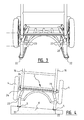
- Figure 6 shows the situation in which the wheels are situated in the lower position
- figure 7 shows the situation in which the wheels are situated in the higher position (wherein for the sake of clarity the wheels are shown only with broken lines).
- the adjusting mechanism for adjusting the two right-hand wheels is described below.
- the operation of the adjusting mechanism on the left-hand side of the pushchair is similar, and a detailed description thereof is therefore dispensed with for the sake of simplicity.
- Rear wheel 4 is mounted with its axle on a pivot shaft 33 which can rotate in a pivotable arm 32. At its opposite outer end pivotable arm 32 is mounted on support carriage 2 via a shaft 50. Front wheel 4 is connected in similar manner via shaft 43 to a pivotable arm 42. Pivotable arm 42 is mounted on support carriage 2 via a further shaft 50. Pivotable arm 32 of the rear wheel and the corresponding arm 42 of the front wheel are mutually connected by a transverse rod 36. This transverse rod 36 is also arranged pivotally on each of the arms 32, 42.
- Arms 32, 42 and 36 together form a parallelogram construction.
- This parallelogram construction makes it possible to adjust both wheels in the height in one movement by rotating the arms 32, 42 to the left or right.
- Two locking mechanisms are provided for the purpose of securing the wheels in the respective end positions (i.e. the high position and the low position).
- a locking mechanism with which shaft 33 of the wheel can be arranged in an opening 40 between a pivotally locked part 38 and a fixedly locked part 37.
- This displaceable locking part 38 forms a hook with which shaft 33 can be retained. Using the shown spring means 39 this hook remains in principle in the closed position so that the wheel remains secured in the shown lower position.
- a similar locking mechanism 41 for locking the shaft of the wheel in the upper position as shown in figure 7 .
- the pushchair can hereby be moved quickly and easily from the one position to the other by unlocking the associated locking mechanism and pushing the rear wheels upward or downward. Unlocking of the respective locking mechanism can take place manually, although in other embodiments an operating mechanism (not shown in the drawing) is also provided with which the locking can be released for instance using the foot.
- the pushchair comprises a support carriage 59 on which three wheels 61, 62, 63 are mounted.
- the support carriage has two rear wheels 61,62 provided laterally of the support carriage and a front wheel 63 arranged centrally on the foremost part of the support carriage.
- the support carriage comprises a frame 60 on the upper surface or loading surface on which two hinges 65 are formed. Uprights 64 of a transport bar 67 can be attached to the hinges.
- the transport bar is shown in the position of use, wherein it can be grasped by a user in order to push the support carriage 59 forward and/or steer it (when the support carriage is electrically propelled).
- the transport bar is positioned folded down onto the loading surface of the support carriage.
- frame 60 further comprises a number of longitudinal girders 70, 71 on which a steel shell is arranged.
- the steel shell comprises a flat upper part 72 (also referred to here as the loading surface) and a part 73 depending on either side.
- the shell provides protection for the internal parts of the support carriage and substantially only the wheels 61, 62 protrude laterally relative to the shell.
- elongate openings Arranged in the shell are a number of elongate openings which have the main purpose of reducing the weight of the shell.
- An elongate slot 88 which curves to some extent is further arranged in each of the depending parts 73. This slot 88 forms a guide opening along which the shafts of wheels 61, 62 can be displaced when the wheels are folded upward or downward.
- the lower edge of the depending parts 73 is bent to some extent and hereby forms slide surfaces 91 over which the pushchair can slide when the wheels are folded upward. At the front the slide surfaces 91 continue into the slide surfaces of two curved strips 90 attached to the depending parts 73.
- a front bracket 75 is attached to frame 60.
- This bracket 75 is mounted on an L-shaped arm 77 using hinges 76.
- Hinges 76 are mounted here on a first outer end of arm 77, while hinges 78 are provided on the opposite outer end of L-shaped arm 77 for rotatably receiving the axle of wheel 63.
- the L-shaped arm 77 can be rotated around hinges 76 in order to displace wheel 63 between the downward folded position shown in figures 9 and 10 and the folded-away position shown in figure 11 . In the folded-away position at least a part of wheel 63 is accommodated in a receiving housing 74 of frame 60 so that the wheel is well protected in this position.
- a second support component 84 is arranged on the rear part of frame 60.
- a shaft 83 is mounted rotatably in this support 84.
- Two parallel arms 82 are formed on shaft 83.
- a hinge 81 Provided roughly in the middle of these arms is a hinge 81, while a further hinge 82 is arranged on the outer end of arms 82 which lies opposite shaft 83.
- Further provided on shaft 83 are two arms 87 and 86 oriented laterally outward to some extent. These arms are substantially L-shaped, wherein a wheel 61, 62 is arranged on each short outer end of an arm. Wheels 61, 62 can be pivoted upward or downward by rotating the arms 82 over shaft 83.
- a coupling arm 80 is mounted pivotally between the two pivoting constructions.
- the coupling arm is more particularly attached at the one outer end to hinges 79 of L-shaped arm 77 with which front wheel 63 can be pivoted, while at the opposite outer end coupling arm 80 is attached to the parallel arms 82 with which rear wheels 61, 62 can be pivoted.
- Coupling arm 80 ensures that a pivoting movement of one of the front arms 77 or rear arms 82 is likewise performed by the other arms 77, 82.
- a third bracket 93 is arranged at a position between bracket 75 and bracket 84.
- a drive 94 for the height adjustment can be fixed to this bracket.
- drive 94 is mounted between bracket 93 and the lower outer end of arms 82 and can pivot relative to the bracket and said arms 82.
- Drive 94 comprises a lifting cylinder 97 in which a plunger 95 can be reciprocally displaced.
- the distance between support 93 and the lower outer end of arms 82 can be varied (direction P 1 ; figure 10 ) by operating lifting cylinder 97.
- the distance is for instance made larger by extending the plunger 95, rear wheels 61, 62 are pivoted downward from the folded-away position shown in figure 11 to the downward folded position shown in figure 10 .
- arms 82 are connected via the above described coupling arm 80 to the mounting of the front wheel, coupling arm 80 will be displaced in forward or rearward direction (P 2 , figure 10 ) when cylinder 95 is extended.
- the drive 94 comprises an electrical, pneumatic and/or hydraulic lifting cylinder.
- An electric lifting cylinder is powered by one or more batteries 100 situated (and shown only schematically) on the rear side of the pushchair ( figure 11 ). The batteries are also applied to provide the control circuits of possible pneumatic and/or hydraulic lifting cylinders with electric power.
- Drive 94 can be operated using an operating element 101 on transport bar 67 so that the user can easily fold the wheels downward or upward.
- the drive for the height adjustment takes a powerful form such that the wheels can be folded in and out while a load, for instance a child's seat with child (with a weight of more than 30 kg or even more than 100 kg) is mounted at the same moment on the loading surface of the frame.
- front wheel 63 is provided with an electric drive 99 for propelling the pushchair over a ground surface.
- the electric drive comprises an electric hub motor which drives the hub of wheel 63.
- the power supply to electric drive 99 can be the same battery 100 also used as power supply for driving the height adjustment of the wheels.
- Electric motor 99 can be operated by the user using the above-mentioned control 101. In some embodiments it is possible to propel the device manually (for instance with motor 99 switched off) as well as to drive the device using the motor. It is further possible in determined embodiments to use motor 99 only as auxiliary motor, wherein the user can additionally increase or decrease the speed of the device by pushing against or pulling on the transport bar.
- the drive of wheels 63 is only suitable for transporting the device when the wheels are folded downward.
- the wheels are folded upward and the pushchair is used as sledge, there is no driving.
- means can be provided with which the device can also be propelled when used as sledge.
- the flat loading surface of the support carriage is also embodied on the one hand to arrange one or more child's seats thereon and on the other to provide space for fastening another load thereto, such as luggage and the like.
- the loads can be attached at any random position to the loading surface subject to the wishes of the user. Use is preferably made here of snap connections so that the load can be attached quickly and securely to the support carriage or be released therefrom.
Landscapes
- Engineering & Computer Science (AREA)
- Chemical & Material Sciences (AREA)
- Combustion & Propulsion (AREA)
- Transportation (AREA)
- Mechanical Engineering (AREA)
- Handcart (AREA)
- Carriages For Children, Sleds, And Other Hand-Operated Vehicles (AREA)
Applications Claiming Priority (1)
| Application Number | Priority Date | Filing Date | Title |
|---|---|---|---|
| NL2007446A NL2007446C2 (nl) | 2011-09-20 | 2011-09-20 | Kinderwagen. |
Publications (2)
| Publication Number | Publication Date |
|---|---|
| EP2676861A2 true EP2676861A2 (fr) | 2013-12-25 |
| EP2676861A3 EP2676861A3 (fr) | 2017-02-22 |
Family
ID=47225929
Family Applications (1)
| Application Number | Title | Priority Date | Filing Date |
|---|---|---|---|
| EP12185128.1A Withdrawn EP2676861A3 (fr) | 2011-09-20 | 2012-09-20 | Poussette |
Country Status (2)
| Country | Link |
|---|---|
| EP (1) | EP2676861A3 (fr) |
| NL (1) | NL2007446C2 (fr) |
Cited By (2)
| Publication number | Priority date | Publication date | Assignee | Title |
|---|---|---|---|---|
| DE202018001827U1 (de) | 2018-04-11 | 2018-05-30 | Rolf Trassl | Lenkschlitten mit elektrischem Antrieb |
| EP3640115A1 (fr) * | 2018-10-19 | 2020-04-22 | FEIL GmbH | Palette roulante |
Families Citing this family (1)
| Publication number | Priority date | Publication date | Assignee | Title |
|---|---|---|---|---|
| US12473006B1 (en) * | 2023-03-27 | 2025-11-18 | Jessica Walters | Car seat transport device |
Family Cites Families (4)
| Publication number | Priority date | Publication date | Assignee | Title |
|---|---|---|---|---|
| US1094420A (en) * | 1912-06-14 | 1914-04-28 | Charley G Bergren | Sled-runner attachment. |
| CH267834A (de) * | 1941-06-21 | 1950-04-15 | Moltke Hansen Georges Ivar Ott | Anhänger. |
| US2521330A (en) * | 1947-09-16 | 1950-09-05 | Albert H Berra | Sled runner attachment for baby buggies |
| DE4111010A1 (de) * | 1990-06-25 | 1992-01-02 | Matthias Kleefisch | Montage- und fahrgestell fuer einen auto-kindersitz |
-
2011
- 2011-09-20 NL NL2007446A patent/NL2007446C2/nl active
-
2012
- 2012-09-20 EP EP12185128.1A patent/EP2676861A3/fr not_active Withdrawn
Non-Patent Citations (1)
| Title |
|---|
| None |
Cited By (2)
| Publication number | Priority date | Publication date | Assignee | Title |
|---|---|---|---|---|
| DE202018001827U1 (de) | 2018-04-11 | 2018-05-30 | Rolf Trassl | Lenkschlitten mit elektrischem Antrieb |
| EP3640115A1 (fr) * | 2018-10-19 | 2020-04-22 | FEIL GmbH | Palette roulante |
Also Published As
| Publication number | Publication date |
|---|---|
| EP2676861A3 (fr) | 2017-02-22 |
| NL2007446C2 (nl) | 2013-03-21 |
Similar Documents
| Publication | Publication Date | Title |
|---|---|---|
| US9873476B2 (en) | Foldable electric vehicle | |
| US20180015978A1 (en) | Convertible Scooter and Handcart | |
| US9272739B2 (en) | Urban vehicle | |
| EP3063056B1 (fr) | Véhicule électrique pliable | |
| US10654541B2 (en) | Convertible scooter | |
| US8453771B1 (en) | Beach wagon | |
| CN203111243U (zh) | 可折叠载客推车 | |
| US20100025968A1 (en) | Compact collapsible stroller | |
| CN107922028B (zh) | 可转换成推车的自行车 | |
| US9365254B1 (en) | Mobility scooter | |
| US6283238B1 (en) | Motorized golf bag cart | |
| US7125080B1 (en) | Foldable armrest for chair | |
| US20190210627A1 (en) | Steering system for tricycle | |
| CN102448803A (zh) | 人力通勤车辆 | |
| CN106080892B (zh) | 电动滑板车 | |
| CN220430390U (zh) | 一种新型载人折叠电动拖车 | |
| CN110723191B (zh) | 折叠儿童推车 | |
| EP2676861A2 (fr) | Poussette | |
| US20250058847A1 (en) | Foldable Vehicle | |
| CN224112239U (zh) | 电动旅行箱 | |
| CN215622037U (zh) | 一种建筑施工用手推车 | |
| CA2813753C (fr) | Adaptateur pour voiturette de golf motorisee avec roue d'entrainement centrale et roues stabilisatrices externes | |
| CN216834083U (zh) | 一种电驱动轻载式板车 | |
| TWI277560B (en) | Human-powered vehicle | |
| GB2419329A (en) | Folding collapsible golf cart |
Legal Events
| Date | Code | Title | Description |
|---|---|---|---|
| PUAI | Public reference made under article 153(3) epc to a published international application that has entered the european phase |
Free format text: ORIGINAL CODE: 0009012 |
|
| AK | Designated contracting states |
Kind code of ref document: A2 Designated state(s): AL AT BE BG CH CY CZ DE DK EE ES FI FR GB GR HR HU IE IS IT LI LT LU LV MC MK MT NL NO PL PT RO RS SE SI SK SM TR |
|
| AX | Request for extension of the european patent |
Extension state: BA ME |
|
| RIC1 | Information provided on ipc code assigned before grant |
Ipc: B62B 5/00 20060101ALN20161011BHEP Ipc: B62B 13/18 20060101ALI20161011BHEP Ipc: B62B 7/14 20060101ALI20161011BHEP Ipc: B62B 7/12 20060101AFI20161011BHEP |
|
| PUAL | Search report despatched |
Free format text: ORIGINAL CODE: 0009013 |
|
| AK | Designated contracting states |
Kind code of ref document: A3 Designated state(s): AL AT BE BG CH CY CZ DE DK EE ES FI FR GB GR HR HU IE IS IT LI LT LU LV MC MK MT NL NO PL PT RO RS SE SI SK SM TR |
|
| AX | Request for extension of the european patent |
Extension state: BA ME |
|
| RIC1 | Information provided on ipc code assigned before grant |
Ipc: B62B 7/12 20060101AFI20170116BHEP Ipc: B62B 5/00 20060101ALN20170116BHEP Ipc: B62B 13/18 20060101ALI20170116BHEP Ipc: B62B 7/14 20060101ALI20170116BHEP |
|
| 17P | Request for examination filed |
Effective date: 20170822 |
|
| RBV | Designated contracting states (corrected) |
Designated state(s): AL AT BE BG CH CY CZ DE DK EE ES FI FR GB GR HR HU IE IS IT LI LT LU LV MC MK MT NL NO PL PT RO RS SE SI SK SM TR |
|
| 17Q | First examination report despatched |
Effective date: 20180612 |
|
| STAA | Information on the status of an ep patent application or granted ep patent |
Free format text: STATUS: THE APPLICATION IS DEEMED TO BE WITHDRAWN |
|
| 18D | Application deemed to be withdrawn |
Effective date: 20190103 |