EP2677101A2 - Installation de porte coulissante automatique - Google Patents
Installation de porte coulissante automatique Download PDFInfo
- Publication number
- EP2677101A2 EP2677101A2 EP13173036.8A EP13173036A EP2677101A2 EP 2677101 A2 EP2677101 A2 EP 2677101A2 EP 13173036 A EP13173036 A EP 13173036A EP 2677101 A2 EP2677101 A2 EP 2677101A2
- Authority
- EP
- European Patent Office
- Prior art keywords
- sliding
- sliding door
- door system
- transmission element
- power transmission
- Prior art date
- Legal status (The legal status is an assumption and is not a legal conclusion. Google has not performed a legal analysis and makes no representation as to the accuracy of the status listed.)
- Withdrawn
Links
- 230000005540 biological transmission Effects 0.000 claims abstract description 29
- 238000006073 displacement reaction Methods 0.000 claims description 3
- 238000010276 construction Methods 0.000 description 2
- 238000010586 diagram Methods 0.000 description 1
- 230000000977 initiatory effect Effects 0.000 description 1
- 230000001953 sensory effect Effects 0.000 description 1
Images
Classifications
-
- E—FIXED CONSTRUCTIONS
- E05—LOCKS; KEYS; WINDOW OR DOOR FITTINGS; SAFES
- E05D—HINGES OR SUSPENSION DEVICES FOR DOORS, WINDOWS OR WINGS
- E05D15/00—Suspension arrangements for wings
- E05D15/48—Suspension arrangements for wings allowing alternative movements
-
- E—FIXED CONSTRUCTIONS
- E05—LOCKS; KEYS; WINDOW OR DOOR FITTINGS; SAFES
- E05D—HINGES OR SUSPENSION DEVICES FOR DOORS, WINDOWS OR WINGS
- E05D15/00—Suspension arrangements for wings
- E05D15/06—Suspension arrangements for wings for wings sliding horizontally more or less in their own plane
- E05D15/0617—Suspension arrangements for wings for wings sliding horizontally more or less in their own plane of cantilever type
-
- E—FIXED CONSTRUCTIONS
- E05—LOCKS; KEYS; WINDOW OR DOOR FITTINGS; SAFES
- E05D—HINGES OR SUSPENSION DEVICES FOR DOORS, WINDOWS OR WINGS
- E05D15/00—Suspension arrangements for wings
- E05D15/48—Suspension arrangements for wings allowing alternative movements
- E05D2015/482—Suspension arrangements for wings allowing alternative movements for panic doors
-
- E—FIXED CONSTRUCTIONS
- E05—LOCKS; KEYS; WINDOW OR DOOR FITTINGS; SAFES
- E05D—HINGES OR SUSPENSION DEVICES FOR DOORS, WINDOWS OR WINGS
- E05D15/00—Suspension arrangements for wings
- E05D15/48—Suspension arrangements for wings allowing alternative movements
- E05D2015/485—Swinging or sliding movements
-
- E—FIXED CONSTRUCTIONS
- E05—LOCKS; KEYS; WINDOW OR DOOR FITTINGS; SAFES
- E05Y—INDEXING SCHEME ASSOCIATED WITH SUBCLASSES E05D AND E05F, RELATING TO CONSTRUCTION ELEMENTS, ELECTRIC CONTROL, POWER SUPPLY, POWER SIGNAL OR TRANSMISSION, USER INTERFACES, MOUNTING OR COUPLING, DETAILS, ACCESSORIES, AUXILIARY OPERATIONS NOT OTHERWISE PROVIDED FOR, APPLICATION THEREOF
- E05Y2201/00—Constructional elements; Accessories therefor
- E05Y2201/60—Suspension or transmission members; Accessories therefor
- E05Y2201/622—Suspension or transmission members elements
- E05Y2201/644—Flexible elongated pulling elements
- E05Y2201/654—Cables
Definitions
- the invention relates to a sliding door system according to the preamble of patent claim 1.
- such sliding door systems such as automatic sliding door systems with at least one driven by a drive means, slidably guided on a guide slide slide, already known which can be used in an escape route by the sliding sash by manual force from a substantially in the plane of Sliding door system located, the normal operation of the sliding door system corresponding basic position in at least one escape route position is pivotable.
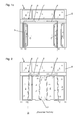
- the basic position of the sliding panel After leaving the basic position of the sliding panel is held on top only in the region of its Mauscharterieskante, so that it can come to a Hauptsch concentratedkanten medicalen lowering the pivoted sash by the occurring tilting moment, as in Fig. 2 is shown.
- the invention has for its object to further develop a generic sliding door system such that the compensation device is easy to install and adjustable and takes up little space.
- the compensation device has a flexible force transmission element, which connects an upper-side guide element or a component connected thereto to a lower-side guide element or a component connected thereto and is guided over at least one fixedly arranged deflecting element.
- a flexible force transmission element which connects an upper-side guide element or a component connected thereto to a lower-side guide element or a component connected thereto and is guided over at least one fixedly arranged deflecting element.
- the flexible power transmission element may be formed as a wire rope or chain or belt or the like, wherein the material used should not stretch significantly under tensile load.
- the deflecting element can be designed as a roller and thus allows a low-friction guidance of the flexible force transmission element.
- the first end of the flexible power transmission element is articulated to the upper side guide member or component in a substantially opposite direction as the second end of the flexible power transmission member to the lower side guide member or component, whereby the upper linkage of the flexible power transmission element as a fixed point for the lower linkage is used.
- the at least one deflection element is arranged so that the flexible force transmission element runs along during a displacement movement of the sliding leaf.
- the flexible power transmission element for normal operation of the sliding door system is not an obstacle.
- the sliding door system can be designed as an automatic sliding door system in that the sliding leaf can be driven by a drive device.
- the article according to the invention in a sliding door system with manually operable sliding sashes.
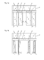
- the sliding door system 1 has two opposite directions by a common drive device 6 driven sliding leaf 2, which are guided on the top side by means of at least one guide member 8 slidably on a stationary guide means 7, for example by means of roller carriage on a guide rail, which together with the drive means 6 on a stationary frame structure 5, for example on a frame part of a mullion transom Construction is arranged above the passage area of the sliding door system 1.
- two side wings 3 are arranged, which extend in a plane closely adjacent to the sliding sashes 2. The side wings 3 are not moved during normal operation of the sliding door system 1.
- Above the drive means 6, a plurality of skylights 4 are present in the illustrated sliding door system 1.
- the sliding leaves 2 have, in the region of their secondary closing edges, pivot bearings which allow pivoting about the pivot axes 10 (direction of movement arrow B).
- the upper pivot bearing is arranged in the region of a support profile 9, which is suspended on the two roller carriage 8, while the lower pivot bearing can be arranged in the region of a bottom guide element, not shown here.
- locking devices are present, which may have, for example latching and / or permanent magnet elements whose holding force must be overcome by the manual application of force.
- the locking devices can be arranged, for example, in each case between the support profile 9 and the sliding leaf 2.
- the two side wings 3 also out of its basic position swing out about pivot axes 11 in the direction of escape, including the side wings also have pivot bearing and locking devices. Furthermore, it is possible to push the already pivoted sliding sash 2 manually aside, as it is in the Fig. 1 c (Direction of movement arrow C) is shown.
- the pivoting of the sliding sash 2 and preferably also the side wing 3 can also be carried out when there is no emergency situation, but an object is to be brought through the sliding door system 1, whose width is greater than the opening width of the sliding sash.
- FIG. 2 is a belonging to the prior art sliding door system 1 immediately after the initiation of pivoting (direction of movement arrow B) of the sliding sash 2, that is shown immediately after cancellation of the basic position.
- the sliding sashes 2 are then supported at the top side only in the region of their secondary closing edges on the support profiles 9, so that the then acting tilting moment causes a lowering of the tiersch concentratedkanten departmenten areas of the sliding sash 2 (pivot angle ⁇ , direction of movement arrow D) and the sliding sash 2 put on the floor 12 can, which hinder the further pivoting of the sliding sash 2 and / or cause damage to the floor covering.
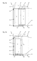
- Fig. 3a and 3b is the advantageous compensation device of the sliding door system 1 according to the invention for two positions of in Fig. 1 left sliding wing 2 shown.
- the compensation device comprises a flexible force transmission element 17, which is designed in this embodiment as a wire rope, but may be designed in different embodiments as a chain, belt or the like. It is essential that the length of the flexible power transmission element 17 should not increase significantly even under load.
- the one end of the flexible power transmission element 17 is in the upper region of the sliding leaf 2 on the support section 9, that is attached to a connected to the top side guide member 8 component.
- the flexible power transmission element 17 is aligned substantially horizontally in this area and is guided via a first deflection element 18, which is mounted in an inner space 16 of the stationary frame structure 5, substantially vertically down to a second deflection element 19, which in the interior 15 of a Bottom 12 recessed guide means 14 is mounted. From there, the flexible power transmission element 17 extends substantially horizontally parallel to the extension of the guide device 14 to a third deflecting element 20 which directs the flexible power transmission element 17 in the opposite direction to a lower-side guide element 13 of the sliding leaf 2, with which the other end of the flexible power transmission element 17th connected is. The first end of the flexible power transmission element 17 thus engages in the opposite direction to a connected to the sliding panel 2 component as the second end of the flexible power transmission element 17.
- the upper, first point of the flexible power transmission element 17 thus serves as a fixed point for the lower point of application of the flexible power transmission element 17 and acts when pivoting the Sliding wing 2 counteracting tilting moment, so that a lowering of the main closing edge side region of the sliding leaf 2 is prevented.
- the points of attack of the flexible power transmission element 17 may differ from the embodiment shown.
- the upper point of application may be located directly on the upper-side guide element 8 or another component connected thereto, and also the lower point of application may lie on another component connected to the lower-side guide element 13.
Landscapes
- Engineering & Computer Science (AREA)
- Mechanical Engineering (AREA)
- Power-Operated Mechanisms For Wings (AREA)
Applications Claiming Priority (1)
| Application Number | Priority Date | Filing Date | Title |
|---|---|---|---|
| DE102012210594A DE102012210594A1 (de) | 2012-06-22 | 2012-06-22 | Schiebetüranlage |
Publications (2)
| Publication Number | Publication Date |
|---|---|
| EP2677101A2 true EP2677101A2 (fr) | 2013-12-25 |
| EP2677101A3 EP2677101A3 (fr) | 2018-01-17 |
Family
ID=48703164
Family Applications (1)
| Application Number | Title | Priority Date | Filing Date |
|---|---|---|---|
| EP13173036.8A Withdrawn EP2677101A3 (fr) | 2012-06-22 | 2013-06-20 | Installation de porte coulissante automatique |
Country Status (2)
| Country | Link |
|---|---|
| EP (1) | EP2677101A3 (fr) |
| DE (1) | DE102012210594A1 (fr) |
Cited By (1)
| Publication number | Priority date | Publication date | Assignee | Title |
|---|---|---|---|---|
| WO2024211937A1 (fr) * | 2023-04-12 | 2024-10-17 | Julius Blum Gmbh | Système de guidage pour supporter avec mobilité au moins un élément de couverture |
Families Citing this family (2)
| Publication number | Priority date | Publication date | Assignee | Title |
|---|---|---|---|---|
| US10415289B2 (en) * | 2017-08-21 | 2019-09-17 | French Slide Llc | Door system with sliding and hinging capability |
| DE102022209510A1 (de) * | 2022-09-12 | 2024-03-14 | Geze Gmbh | Beschlag für eine Schiebetür sowie Schiebetür |
Family Cites Families (3)
| Publication number | Priority date | Publication date | Assignee | Title |
|---|---|---|---|---|
| DE869611C (de) * | 1950-11-28 | 1953-03-05 | Josef Stocker | Aus der Schliessstellung fortbewegbarer Mittelfluegel |
| DE2847578A1 (de) * | 1978-11-02 | 1980-05-08 | Schock Metallwerk | Fuehrungsvorrichtung fuer an einem traeger linear verstellbar angeordnete gegenstaende, insbesondere zur parallelverstellung von moebeleinschueben |
| DE3101725A1 (de) | 1981-01-21 | 1982-08-05 | Aktiengesellschaft für Türautomation, 8600 Dübendorf | "schiebetueranlage" |
-
2012
- 2012-06-22 DE DE102012210594A patent/DE102012210594A1/de not_active Withdrawn
-
2013
- 2013-06-20 EP EP13173036.8A patent/EP2677101A3/fr not_active Withdrawn
Non-Patent Citations (1)
| Title |
|---|
| None * |
Cited By (1)
| Publication number | Priority date | Publication date | Assignee | Title |
|---|---|---|---|---|
| WO2024211937A1 (fr) * | 2023-04-12 | 2024-10-17 | Julius Blum Gmbh | Système de guidage pour supporter avec mobilité au moins un élément de couverture |
Also Published As
| Publication number | Publication date |
|---|---|
| EP2677101A3 (fr) | 2018-01-17 |
| DE102012210594A1 (de) | 2013-12-24 |
Similar Documents
| Publication | Publication Date | Title |
|---|---|---|
| EP2829679B1 (fr) | Ferrure pour l'appui d'un battant mobile contre une bordure fixe | |
| EP2143862B1 (fr) | Vitre orientable parallèle | |
| DE3738596C2 (fr) | ||
| EP2677101A2 (fr) | Installation de porte coulissante automatique | |
| EP2476857A2 (fr) | Installation de porte coulissante avec joint descendant | |
| EP1427907B1 (fr) | Systeme de cloison coulissante avec un element de battant de porte coulissant et pivotant | |
| DE4410051C2 (de) | Sektionaltor | |
| EP0468223B1 (fr) | Porte accordéon | |
| CH714546A2 (de) | Vorrichtung zum Öffnen einer Gebäudedachöffnung. | |
| DE102011077631B4 (de) | Automatische Schiebetüranlage | |
| EP4484694A1 (fr) | Agencement de porte coulissante | |
| EP3480407A1 (fr) | Élément coulissant vertical | |
| DE102012210584B4 (de) | Schiebetüranlage | |
| EP0851083A1 (fr) | Fenêtre coulissant verticalement | |
| AT526849B1 (de) | Führungssystem zur Führung wenigstens eines bewegbar gelagerten Türflügels entlang einer Möbelwand | |
| DE19545375C2 (de) | Tür insbesondere Falttür | |
| CH688593A5 (de) | Faltbare Vorrichtung zum Verschliessen von Gebaeude oeffnungen, insbesondere fuer ein Faltdach oder Falttor. | |
| EP3511480B1 (fr) | Dispositif d'ouverture d'une ouverture de toit de bâtiment | |
| DE202017104052U1 (de) | Laufschienenanordnung für ein Sektionaltor | |
| DE7918647U1 (de) | Schiebetuer | |
| DE2639954A1 (de) | Ausstellvorrichtung fuer kippfluegel o.dgl. | |
| DE19631463B4 (de) | Vorrichtung zum Kippen eines Flächenelements | |
| DE3411544A1 (de) | Sektionaltor | |
| DE10238627A1 (de) | Beschlagelement | |
| CH688830A5 (de) | Sektionaltor. |
Legal Events
| Date | Code | Title | Description |
|---|---|---|---|
| PUAI | Public reference made under article 153(3) epc to a published international application that has entered the european phase |
Free format text: ORIGINAL CODE: 0009012 |
|
| AK | Designated contracting states |
Kind code of ref document: A2 Designated state(s): AL AT BE BG CH CY CZ DE DK EE ES FI FR GB GR HR HU IE IS IT LI LT LU LV MC MK MT NL NO PL PT RO RS SE SI SK SM TR |
|
| AX | Request for extension of the european patent |
Extension state: BA ME |
|
| PUAL | Search report despatched |
Free format text: ORIGINAL CODE: 0009013 |
|
| AK | Designated contracting states |
Kind code of ref document: A3 Designated state(s): AL AT BE BG CH CY CZ DE DK EE ES FI FR GB GR HR HU IE IS IT LI LT LU LV MC MK MT NL NO PL PT RO RS SE SI SK SM TR |
|
| AX | Request for extension of the european patent |
Extension state: BA ME |
|
| RIC1 | Information provided on ipc code assigned before grant |
Ipc: E05F 7/06 20060101ALI20171208BHEP Ipc: E05D 15/48 20060101AFI20171208BHEP Ipc: E05D 15/06 20060101ALI20171208BHEP |
|
| 17P | Request for examination filed |
Effective date: 20180704 |
|
| RBV | Designated contracting states (corrected) |
Designated state(s): AL AT BE BG CH CY CZ DE DK EE ES FI FR GB GR HR HU IE IS IT LI LT LU LV MC MK MT NL NO PL PT RO RS SE SI SK SM TR |
|
| 17Q | First examination report despatched |
Effective date: 20190611 |
|
| STAA | Information on the status of an ep patent application or granted ep patent |
Free format text: STATUS: THE APPLICATION HAS BEEN WITHDRAWN |
|
| 18W | Application withdrawn |
Effective date: 20200507 |