EP2677104B1 - Armoire de sécurité - Google Patents
Armoire de sécurité Download PDFInfo
- Publication number
- EP2677104B1 EP2677104B1 EP13167656.1A EP13167656A EP2677104B1 EP 2677104 B1 EP2677104 B1 EP 2677104B1 EP 13167656 A EP13167656 A EP 13167656A EP 2677104 B1 EP2677104 B1 EP 2677104B1
- Authority
- EP
- European Patent Office
- Prior art keywords
- connecting element
- swing door
- door
- swing
- closing
- Prior art date
- Legal status (The legal status is an assumption and is not a legal conclusion. Google has not performed a legal analysis and makes no representation as to the accuracy of the status listed.)
- Active
Links
Images

Classifications
-
- E—FIXED CONSTRUCTIONS
- E05—LOCKS; KEYS; WINDOW OR DOOR FITTINGS; SAFES
- E05F—DEVICES FOR MOVING WINGS INTO OPEN OR CLOSED POSITION; CHECKS FOR WINGS; WING FITTINGS NOT OTHERWISE PROVIDED FOR, CONCERNED WITH THE FUNCTIONING OF THE WING
- E05F1/00—Closers or openers for wings, not otherwise provided for in this subclass
- E05F1/08—Closers or openers for wings, not otherwise provided for in this subclass spring-actuated, e.g. for horizontally sliding wings
- E05F1/10—Closers or openers for wings, not otherwise provided for in this subclass spring-actuated, e.g. for horizontally sliding wings for swinging wings, e.g. counterbalance
-
- E—FIXED CONSTRUCTIONS
- E05—LOCKS; KEYS; WINDOW OR DOOR FITTINGS; SAFES
- E05F—DEVICES FOR MOVING WINGS INTO OPEN OR CLOSED POSITION; CHECKS FOR WINGS; WING FITTINGS NOT OTHERWISE PROVIDED FOR, CONCERNED WITH THE FUNCTIONING OF THE WING
- E05F17/00—Special devices for shifting a plurality of wings operated simultaneously
- E05F17/004—Special devices for shifting a plurality of wings operated simultaneously for wings which abut when closed
-
- E—FIXED CONSTRUCTIONS
- E05—LOCKS; KEYS; WINDOW OR DOOR FITTINGS; SAFES
- E05G—SAFES OR STRONG-ROOMS FOR VALUABLES; BANK PROTECTION DEVICES; SAFETY TRANSACTION PARTITIONS
- E05G1/00—Safes or strong-rooms for valuables
-
- E—FIXED CONSTRUCTIONS
- E05—LOCKS; KEYS; WINDOW OR DOOR FITTINGS; SAFES
- E05G—SAFES OR STRONG-ROOMS FOR VALUABLES; BANK PROTECTION DEVICES; SAFETY TRANSACTION PARTITIONS
- E05G1/00—Safes or strong-rooms for valuables
- E05G1/02—Details
- E05G1/026—Closures
-
- E—FIXED CONSTRUCTIONS
- E05—LOCKS; KEYS; WINDOW OR DOOR FITTINGS; SAFES
- E05F—DEVICES FOR MOVING WINGS INTO OPEN OR CLOSED POSITION; CHECKS FOR WINGS; WING FITTINGS NOT OTHERWISE PROVIDED FOR, CONCERNED WITH THE FUNCTIONING OF THE WING
- E05F1/00—Closers or openers for wings, not otherwise provided for in this subclass
- E05F1/002—Closers or openers for wings, not otherwise provided for in this subclass controlled by automatically acting means
- E05F1/006—Closers or openers for wings, not otherwise provided for in this subclass controlled by automatically acting means by emergency conditions, e.g. fire
-
- E—FIXED CONSTRUCTIONS
- E05—LOCKS; KEYS; WINDOW OR DOOR FITTINGS; SAFES
- E05F—DEVICES FOR MOVING WINGS INTO OPEN OR CLOSED POSITION; CHECKS FOR WINGS; WING FITTINGS NOT OTHERWISE PROVIDED FOR, CONCERNED WITH THE FUNCTIONING OF THE WING
- E05F1/00—Closers or openers for wings, not otherwise provided for in this subclass
- E05F1/08—Closers or openers for wings, not otherwise provided for in this subclass spring-actuated, e.g. for horizontally sliding wings
- E05F1/10—Closers or openers for wings, not otherwise provided for in this subclass spring-actuated, e.g. for horizontally sliding wings for swinging wings, e.g. counterbalance
- E05F1/1041—Closers or openers for wings, not otherwise provided for in this subclass spring-actuated, e.g. for horizontally sliding wings for swinging wings, e.g. counterbalance with a coil spring perpendicular to the pivot axis
-
- E—FIXED CONSTRUCTIONS
- E05—LOCKS; KEYS; WINDOW OR DOOR FITTINGS; SAFES
- E05F—DEVICES FOR MOVING WINGS INTO OPEN OR CLOSED POSITION; CHECKS FOR WINGS; WING FITTINGS NOT OTHERWISE PROVIDED FOR, CONCERNED WITH THE FUNCTIONING OF THE WING
- E05F17/00—Special devices for shifting a plurality of wings operated simultaneously
- E05F2017/008—Special devices for shifting a plurality of wings operated simultaneously for swinging wings
-
- E—FIXED CONSTRUCTIONS
- E05—LOCKS; KEYS; WINDOW OR DOOR FITTINGS; SAFES
- E05Y—INDEXING SCHEME ASSOCIATED WITH SUBCLASSES E05D AND E05F, RELATING TO CONSTRUCTION ELEMENTS, ELECTRIC CONTROL, POWER SUPPLY, POWER SIGNAL OR TRANSMISSION, USER INTERFACES, MOUNTING OR COUPLING, DETAILS, ACCESSORIES, AUXILIARY OPERATIONS NOT OTHERWISE PROVIDED FOR, APPLICATION THEREOF
- E05Y2900/00—Application of doors, windows, wings or fittings thereof
- E05Y2900/20—Application of doors, windows, wings or fittings thereof for furniture, e.g. cabinets
- E05Y2900/21—Application of doors, windows, wings or fittings thereof for furniture, e.g. cabinets for safety cabinets
Definitions
- the invention relates to a safety cabinet, in particular Hazardous goods cabinet, with at least two jointly connected to a slidable in a guide connecting pivot doors, the respective swing door is rotatably connected to the cabinet body via a respective edge side a cabinet body arranged axis of rotation, and wherein the respective swing door of the two swing doors is connected by means of a respective own hinge assembly to the connecting element, and with a spring unit, which acts on both swing doors, at least in the closing operation in the direction of its closed position, wherein the closing operation, the connecting element is moved from its open position to a closed position along the guide.
- Safety cabinets and in particular hazardous substance cabinets are typically used for storing mostly flammable hazardous substances such as chemicals, flammable liquids, etc.
- flammable hazardous substances such as chemicals, flammable liquids, etc.
- the security cabinet in question is reliably closed in the closed operation. This is ensured by the spring unit, which ensures in automatic closing operation or in the event of a fire that the two swing doors are reliably and automatically closed.
- a manual and / or motor - and not automatic - opening and closing is provided in normal operation.
- the connecting element can be moved in a guide. This allows the swing doors to open and close synchronously.
- Comparable is in the safety cabinet according to the EP 2 017 420 A1 proceed. Also in this case, two swing doors are connected together to a displaceable in a guide connecting element. At least during closing operation, the spring unit ensures that both swing doors are subjected to a force in the direction of their closed position. In this case, the spring unit is functionally decoupled from the connecting element in normal operation and acted upon this only in the closing operation. In this way, a reliable function of the spring unit is ensured in the closing operation under all circumstances.
- EP 2 221 438 A2 also deals with a safety cabinet in which the spring unit in normal operation, that is, during (manually) caused opening and closing movements of the swing doors, constantly maintains its cocked position.
- the spring unit has a driver, which interacts with the swing doors only in the closing operation, for example in case of fire.
- the swing doors can also be connected in each case to a separate connection element in the course of a two-handed operation in normal operation.
- the swing doors already operate independently, are still closed together with the help of the spring unit in the closing operation.
- the design chosen at this point is technologically relatively complicated and thus in need of improvement.
- the invention is based on the technical problem of further developing a safety cabinet of the construction described above, that with perfect functionality and in particular while maintaining the ability to individually apply the respective swing door in normal operation, nevertheless a safe closing operation with a structurally simple construction for Is made available.
- a safety cabinet according to claim 1 is provided.
- the opening or closing movement of the rotary door in question is accomplished manually and / or motorically in normal operation.
- a manual operation and a manual operation of the swing door in normal operation in question it is ensured in each case that the other rotary door is mechanically decoupled from the connecting element in the normal operation in comparison with the manually applied rotary door.
- a (single) connecting element is used, from which the other rotary door in question is mechanically decoupled in the procedure described.
- the respective swing door of the two swing doors is connected by means of a respective own hinge assembly to the connecting element.
- the joint arrangement is essentially composed of a connecting joint arm which is rotatably coupled to the (single) connecting element and, in addition, a door joint arm rotatably connected to the revolving wing door. That is, the joint assembly for connecting the respective swing door to the connecting element is usually designed in two parts and consists of the already mentioned connecting joint arm and the Mosgelenkarm together.
- Both articulated arms are also connected to each other articulated.
- the connecting joint arm is pivotally connected to the connecting element.
- the Schogelenkarm which forms a pivotal connection with the swing door.
- the articulated arrangement of the rotary wing door acted upon in the course of the opening movement bears against the stop of the connecting element in normal operation.
- two stops are provided on the connecting element for the respective joint arrangement.
- the attacks are according to the invention to door-side stops, that is, stops that are connected to the connecting element in the direction of the swing door.
- the connecting element is usually formed (mirror) symmetrically in comparison to the central guide.
- the stops are arranged substantially at right angles compared to a connection plate. In this case, the terminal plate and the two door-side stops can be made practically in one go become.
- the connecting element has the connection plate in question, which is generally equipped with pivot axes for the rotatable connection of the respective joint arrangement. It has further proven, if the attacks in question include an obtuse angle between them.
- the overall interpretation is such that the hinge assembly door with the connecting element in each case coupling joint arrangement rests in the open position of the respective swing door to the associated door-side stop of the connecting element.
- the closed position of the swing door generally corresponds to the fact that the hinge assembly in this case protrudes angularly from the door-side stop in question.
- the design is made such that the joint arrangement of in the course of the opening or closing movement (in normal operation) acted upon rotary door is adjusted relative to the connecting element. That is, the normal operation corresponds to the connecting member maintaining its open position.
- This opening position of the connecting element (in normal operation) belongs to a door-side end position in comparison to the associated guide. In other words, the connecting element is in the open position (in normal operation) in the immediate vicinity of the (closed) swing door - as it were vis-à-vis.
- This opening position assumes the connecting element in normal operation throughout. If the connecting element is moved into the closed position along the guide, the closing operation, for example a fire, corresponds thereto. In the closing operation, the connecting element is moved from its open position to the closed position along the guide. in this connection at the same time one or both swing doors are closed, provided that they are open.
- the closed position of the connecting element and thus the closing operation corresponds, for example in case of fire to an approximately central position of the connecting element in comparison to the already mentioned guide.
- the longitudinal extension of the guide in question follows the opening / closing direction of the connecting element.
- the connecting element is transverse to the guide extends.
- the opening position of the connecting element belongs to the door-side end position in comparison to the guide.
- the respective swing door can be acted upon individually and independently of the other swing door, for example, manually, in normal operation.
- an opening operation of the relevant swing door in this normal operation corresponds to the fact that the joint arrangement is moved relative to the connecting element.
- the hinge assembly performs an angular movement away from the respective stop of the connecting element.
- the connecting element remains at rest. This also applies to the other swing door, which is mechanically decoupled from the connecting element in question.
- the connecting element remains in its open position during normal operation until the spring unit is activated. In fact, the connecting element is fixed in its open position and its door-side end position. Only in the closing operation, this fixation is canceled. In the event of fire, a thermally dissolved fusible link may cause this. In this way, the spring unit can now move the connecting element in its closed position along the guide.
- the associated swing door is applied closing as soon as the connecting element is transferred from its open position to the closed position by means of the spring unit. This ensures that the safety cabinet according to the invention is closed in the closing operation in any case is and the inside of hazardous materials safe storage in the event of fire.
- the main benefits are the main benefits.
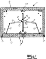
- a safety cabinet and in particular hazardous materials cabinet which has a cabinet body 1, are connected to the swing doors 2.
- the respective swing door 2 is connected via a respective edge of the cabinet body 1 arranged axis of rotation 3 to the cabinet body 1.
- Both the cabinet body 1 and the associated swing door 2 have an inner lining 4, 5, which may be constructed of non-flammable or flame-retardant material plates. It can be seen that in the present case two swing doors 2 are realized, which are connected together to a displaceable in a guide 6 connecting element 7.
- the connecting element 7 is substantially axially symmetrical in comparison to the central guide 6.
- the connecting member 7 extends substantially transversely compared to the longitudinal extent of the guide 6.
- the guide 6 is formed and arranged so that they are along a by an arrow in the Fig. 2 indicated closing movement of the associated Swing door 2 and the connecting element 7 extends.
- the connecting element 7 may engage with a roller assembly, a web, a sword or the like in the embodiment equipped with two rails with a central recess guide 6.
- the connecting element 7 undergoes a linear displacement along the guide 6 as soon as the connecting element 7 moves from its opening position, which is normally assumed during normal operation, in the door-side end position relative to the guide 6 Fig. 2 in the closed position with a central arrangement relative to the guide 6 according to Fig. 1 is transferred.
- the closed position of the connecting element 7 after Fig. 1 corresponds to the closing operation, for example to a fire.
- the respective swing door 2 is connected by means of a hinge arrangement 8, 9 to the connecting element 7.
- the joint arrangement 8, 9 essentially consists of a connection joint arm 8 which is rotatably coupled to the connection element 7 and a door joint arm 9 rotatably connected to the associated swing door 2.
- the connecting joint arm 8 and the Schogelenkarm 9 are in turn hinged together.
- connection plate 11 in question and the associated stops 10 can be produced in a particularly simple and cost-effective manner, namely by means of customary metal stamping / bending processes.
- connection plate 11 is equipped with axes of rotation 12, by means of which the respective joint arrangement 8, 9 is rotatably connected to the connecting element 7.
- the respective connecting joint arm 8 experiences, with the aid of the axes of rotation 12, a rotatable connection to the connecting element 7 or its connecting plate 11. It can be seen that the two stops 10 in total enclose an obtuse angle between them.
- the operation is as follows: Starting from a closed position of both swing doors 2 in normal operation according to the Fig. 2 can be seen that an opening movement of the left wing door 2 in this case to a Relative movement of the hinge assembly 8, 9 relative to the connecting element 7 corresponds.
- the connecting element 7 retains its opening position in normal operation Fig. 2 at, that is, remains in the end position in comparison to the associated guide 6. In this opening position, the connecting element 7 is fixed. This may provide a thermally solvable and not shown fire protection.
- the associated joint assembly 8, 9 goes from its previously assumed and angularly spread position compared to the connecting element 7 in a position that to a system of the associated hinge assembly 8, 9 corresponds to the left stop 10 in the example case. If the stop 10 is reached, then this fact ensures at the same time that any opening angle of the swing door 2 to about 90 ° relative to the cabinet body 1 in the example of the after Fig. 2 is limited. Of course, this is only an example.
- the closing operation for example in the event of a fire, now corresponds to the fact that a spring unit 13 is used.
- the connecting element 7 is thermally dissolved in the open position or door-side end position relative to the guide 6 fixing fire protection.
- the spring unit 13 can now pull the connecting element 7 in the direction of the cabinet rear side along the guide 6.
- the connecting element 7 goes from the opening position corresponding to Fig. 2 in the closed position after the Fig. 1 above. This includes the closing operation.
- both swing doors 2 - if open - closed simultaneously. Because provided in the movement of the connecting element 7 from its opening position according to Fig. 2 in the closed position Fig. 1 are opened in the direction of the cabinet back one or both swing doors 2, this movement of the connecting element 7 ensures that the relevant swing door 2 is closed.
- the connecting element 7 is moved by means of the spring unit 13 along the guide 6, without the relevant Swing door 2 undergoes an admission.
- the connecting joint arm 8 is moved from its angled position into contact with the stop 10 of the connecting element 7.
Landscapes
- Special Wing (AREA)
- Closing And Opening Devices For Wings, And Checks For Wings (AREA)
- Cabinets, Racks, Or The Like Of Rigid Construction (AREA)
Claims (9)
- Armoire de sécurité, notamment armoire de sécurité pour produits dangereux, avec au moins deux portes à battants (2) raccordées conjointement à un élément de liaison (7) pouvant se déplacer dans un guidage (6), La porte à battants (2) étant raccordée à un corps d'armoire (1) par le biais d'un axe de rotation (3) disposé respectivement sur le bord d'un corps d'armoire (1),
La porte à battants respective (2) des deux portes à battants (2) étant raccordée à l'élément de liaison (7) au moyen d'un ensemble articulé respectivement propre (8, 9), et
l'élément de liaison (7) étant équipé de deux butées côté porte (10) pour l'ensemble articulé respectif (8, 9), et
un fonctionnement normal correspondant à cet effet au fait que l'élément de liaison (7) adopte et conserve sa position d'ouverture et par suite une position finale côté porte en comparaison du guidage (6), l'autre porte à battants respective (2) étant, en fonctionnement normal, mécaniquement découplée de l'élément de liaison (7) lors du mouvement d'ouverture ou de fermeture d'une porte à battants (2),
pendant que l'ensemble articulé (8,9) est déplacé au cours du mouvement d'ouverture ou de fermeture de la porte à battants (2) sollicitée en fonctionnement normal par rapport à l'élément de liaison (7) et l'ensemble articulé (8,9) de la porte à battants (2) sollicitée au cours du mouvement d'ouverture vient s'appliquer, en fonctionnement normal, à la butée (10) dans la position d'ouverture de la porte à battants, alors que l'autre porte à battants (2) reste dans sa position de fermeture et avec une unité à ressort (13), laquelle sollicite avec une force les deux portes à battants (2) au moins en fonctionnement de fermeture en direction de leur position de fermeture, en mode de fermeture l'élément de liaison (7) étant transféré de sa position d'ouverture dans une position de fermeture le long du guidage (6) au moyen de l'unité à ressort (13), la porte à battants correspondante (2) étant sollicitée en fermeture par le biais de l'ensemble articulé (8,9) s'appliquant respectivement à la butée (10) de l'élément de liaison (7). - Armoire selon la revendication 1, caractérisée en ce que le mouvement d'ouverture ou de fermeture de la porte à battants (2) est effectué manuellement et/ou de façon motorisée en fonctionnement normal.
- Armoire selon la revendication 1 ou 2 caractérisée en ce que l'ensemble articulé (8,9) est composé pour l'essentiel d'un bras articulé de liaison (8) couplé pouvant tourner à l'élément de liaison (7) et d'un bras articulé de porte (9) relié pouvant tourner à la porte à battants (2).
- Armoire selon l'une quelconque des revendications 1 à 3, caractérisée en ce que la position de fermeture de l'élément de liaison (7) correspond à une position à peu près centrale comparée à un guidage en extension longitudinale (6).
- Armoire selon l'une quelconque des revendications 1 à 4, caractérisée en ce que l'élément de liaison (7) est constitué de façon symétrique en comparaison du guidage central (6).
- Armoire selon l'une quelconque des revendications 1 à 5, caractérisée en ce que l'élément de liaison (7) comporte une plaque de raccord (11) avec des axes de rotation (12) pour le raccordement rotatif de l'ensemble articulé respectif (8,9).
- Armoire selon la revendication 6, caractérisée en ce que les butées (10) sont disposées pour l'essentiel perpendiculairement à la plaque de raccord (11).
- Armoire selon l'une quelconque des revendications 1 à 7, caractérisée en ce que les butées (10) forment un angle obtus entre elles.
- Armoire selon l'une quelconque des revendications 1 à 8, caractérisée en ce que l'ensemble articulé (8,9) s'écarte de façon angulaire de la butée (10) dans la position de fermeture de la porte à battants respective (2).
Priority Applications (1)
| Application Number | Priority Date | Filing Date | Title |
|---|---|---|---|
| PL13167656T PL2677104T3 (pl) | 2012-06-18 | 2013-05-14 | Szafka bezpieczeństwa |
Applications Claiming Priority (2)
| Application Number | Priority Date | Filing Date | Title |
|---|---|---|---|
| DE202012102230U DE202012102230U1 (de) | 2012-06-18 | 2012-06-18 | Sicherheitsschrank |
| DE202012102586U DE202012102586U1 (de) | 2012-06-18 | 2012-07-12 | Sicherheitsschrank |
Publications (3)
| Publication Number | Publication Date |
|---|---|
| EP2677104A2 EP2677104A2 (fr) | 2013-12-25 |
| EP2677104A3 EP2677104A3 (fr) | 2015-10-07 |
| EP2677104B1 true EP2677104B1 (fr) | 2018-04-25 |
Family
ID=46635689
Family Applications (1)
| Application Number | Title | Priority Date | Filing Date |
|---|---|---|---|
| EP13167656.1A Active EP2677104B1 (fr) | 2012-06-18 | 2013-05-14 | Armoire de sécurité |
Country Status (5)
| Country | Link |
|---|---|
| EP (1) | EP2677104B1 (fr) |
| DE (2) | DE202012102230U1 (fr) |
| ES (1) | ES2675552T3 (fr) |
| PL (1) | PL2677104T3 (fr) |
| TR (1) | TR201809309T4 (fr) |
Families Citing this family (5)
| Publication number | Priority date | Publication date | Assignee | Title |
|---|---|---|---|---|
| ES2786227T3 (es) * | 2015-10-01 | 2020-10-09 | Dueperthal Sicherheitstechnik Gmbh & Co Kg | Armario de seguridad |
| ES2746539T3 (es) | 2015-10-01 | 2020-03-06 | Dueperthal Sicherheitstechnik Gmbh & Co Kg | Armario de seguridad |
| DE102016113822B4 (de) * | 2016-07-27 | 2021-04-15 | Asecos Gmbh | Gefahrstoffschrank |
| CN110159135B (zh) * | 2019-06-03 | 2020-08-14 | 秦皇岛职业技术学院 | 一种嵌入式高安全性金融票据存放装置 |
| CN110469231B (zh) * | 2019-08-29 | 2021-04-16 | 中国航空工业集团公司沈阳飞机设计研究所 | 一种对开活动舱门开闭连杆机构 |
Family Cites Families (4)
| Publication number | Priority date | Publication date | Assignee | Title |
|---|---|---|---|---|
| DE202004004855U1 (de) | 2004-03-25 | 2004-08-12 | Asecos Gmbh | Sicherheitsschrank |
| DE102004021912A1 (de) * | 2004-03-25 | 2005-10-13 | Asecos Gmbh | Sicherheitsschrank |
| EP2017420B1 (fr) | 2007-07-20 | 2009-10-07 | Düperthal Sicherheitstechnik GmbH & Co.KG | Armoire, en particulier armoire de sécurité |
| DE202009002534U1 (de) | 2009-02-21 | 2009-04-30 | Düperthal Sicherheitstechnik Gmbh & Co. Kg | Schrank, insbesondere Sicherheitsschrank |
-
2012
- 2012-06-18 DE DE202012102230U patent/DE202012102230U1/de not_active Expired - Lifetime
- 2012-07-12 DE DE202012102586U patent/DE202012102586U1/de not_active Expired - Lifetime
-
2013
- 2013-05-14 EP EP13167656.1A patent/EP2677104B1/fr active Active
- 2013-05-14 TR TR2018/09309T patent/TR201809309T4/tr unknown
- 2013-05-14 ES ES13167656.1T patent/ES2675552T3/es active Active
- 2013-05-14 PL PL13167656T patent/PL2677104T3/pl unknown
Non-Patent Citations (1)
| Title |
|---|
| None * |
Also Published As
| Publication number | Publication date |
|---|---|
| DE202012102586U1 (de) | 2012-08-09 |
| EP2677104A2 (fr) | 2013-12-25 |
| ES2675552T3 (es) | 2018-07-11 |
| EP2677104A3 (fr) | 2015-10-07 |
| DE202012102230U1 (de) | 2012-07-11 |
| TR201809309T4 (tr) | 2018-07-23 |
| PL2677104T3 (pl) | 2018-09-28 |
Similar Documents
| Publication | Publication Date | Title |
|---|---|---|
| EP2893108B1 (fr) | Serrure de porte de véhicule automobile | |
| EP2702218B1 (fr) | Système de fermeture de porte de véhicule automobile | |
| EP3271535B1 (fr) | Porte de véhicule à moteur | |
| EP2677104B1 (fr) | Armoire de sécurité | |
| EP2935736B1 (fr) | Mécanisme de fermeture de porte de véhicule | |
| EP2221438A2 (fr) | Armoire, en particulier armoire de sécurité | |
| EP1862618A1 (fr) | Fermeture de porte de véhicule automobile | |
| DE102016107510A1 (de) | Kraftfahrzeugtürschloss | |
| EP3271539A1 (fr) | Porte de véhicule à moteur | |
| EP1489252A2 (fr) | Serrure de porte pour véhicule automobile | |
| DE10236282B4 (de) | Kraftfahrzeugschloß mit zwei Sperrklinken | |
| EP2017420B1 (fr) | Armoire, en particulier armoire de sécurité | |
| EP2715019B1 (fr) | Verrouillage de portière de véhicule à moteur | |
| DE102013014725A1 (de) | Kraftfahrzeugtürverschluss | |
| EP4112851B1 (fr) | Serrure de véhicule automobile, en particulier serrure de portière de véhicule automobile | |
| EP4133152A1 (fr) | Verrou de véhicule automobile | |
| EP3117057A1 (fr) | Système de fermeture de portière de véhicule automobile | |
| EP2603657B1 (fr) | Armoire, en particulier armoire de sécurité | |
| DE29818045U1 (de) | Beschlag für Klappfenster, insbesondere von Wohnwagen, Mobilheimen u.dgl. | |
| DE2717232C2 (de) | Sicherheitstür für Schaltanlagenzelle | |
| WO2024052381A1 (fr) | Serrure de véhicule à moteur, en particulier serrure de porte de véhicule à moteur | |
| WO2016062309A2 (fr) | Mécanisme de fermeture de porte de véhicule automobile | |
| EP2017418B1 (fr) | Armoire, en particulier armoire de sécurité de trappe | |
| DE102014111876B4 (de) | Beidseitig bedienbarer Drehstangenverschluss für Kofferaufbauten | |
| DE19532263A1 (de) | Vorrichtung zur Schließfolgeregelung für zweiflügelige Türen |
Legal Events
| Date | Code | Title | Description |
|---|---|---|---|
| PUAI | Public reference made under article 153(3) epc to a published international application that has entered the european phase |
Free format text: ORIGINAL CODE: 0009012 |
|
| AK | Designated contracting states |
Kind code of ref document: A2 Designated state(s): AL AT BE BG CH CY CZ DE DK EE ES FI FR GB GR HR HU IE IS IT LI LT LU LV MC MK MT NL NO PL PT RO RS SE SI SK SM TR |
|
| AX | Request for extension of the european patent |
Extension state: BA ME |
|
| PUAL | Search report despatched |
Free format text: ORIGINAL CODE: 0009013 |
|
| AK | Designated contracting states |
Kind code of ref document: A3 Designated state(s): AL AT BE BG CH CY CZ DE DK EE ES FI FR GB GR HR HU IE IS IT LI LT LU LV MC MK MT NL NO PL PT RO RS SE SI SK SM TR |
|
| AX | Request for extension of the european patent |
Extension state: BA ME |
|
| RIC1 | Information provided on ipc code assigned before grant |
Ipc: E05F 17/00 20060101AFI20150902BHEP Ipc: E05G 1/00 20060101ALI20150902BHEP Ipc: E05G 1/026 20060101ALI20150902BHEP Ipc: E05F 1/10 20060101ALI20150902BHEP Ipc: E05F 1/00 20060101ALN20150902BHEP |
|
| 17P | Request for examination filed |
Effective date: 20151111 |
|
| RBV | Designated contracting states (corrected) |
Designated state(s): AL AT BE BG CH CY CZ DE DK EE ES FI FR GB GR HR HU IE IS IT LI LT LU LV MC MK MT NL NO PL PT RO RS SE SI SK SM TR |
|
| GRAP | Despatch of communication of intention to grant a patent |
Free format text: ORIGINAL CODE: EPIDOSNIGR1 |
|
| RIC1 | Information provided on ipc code assigned before grant |
Ipc: E05G 1/00 20060101ALI20171221BHEP Ipc: E05F 17/00 20060101AFI20171221BHEP Ipc: E05F 1/10 20060101ALI20171221BHEP Ipc: E05G 1/026 20060101ALI20171221BHEP Ipc: E05F 1/00 20060101ALN20171221BHEP |
|
| GRAS | Grant fee paid |
Free format text: ORIGINAL CODE: EPIDOSNIGR3 |
|
| INTG | Intention to grant announced |
Effective date: 20180124 |
|
| GRAA | (expected) grant |
Free format text: ORIGINAL CODE: 0009210 |
|
| AK | Designated contracting states |
Kind code of ref document: B1 Designated state(s): AL AT BE BG CH CY CZ DE DK EE ES FI FR GB GR HR HU IE IS IT LI LT LU LV MC MK MT NL NO PL PT RO RS SE SI SK SM TR |
|
| REG | Reference to a national code |
Ref country code: GB Ref legal event code: FG4D Free format text: NOT ENGLISH |
|
| REG | Reference to a national code |
Ref country code: CH Ref legal event code: EP |
|
| REG | Reference to a national code |
Ref country code: AT Ref legal event code: REF Ref document number: 993100 Country of ref document: AT Kind code of ref document: T Effective date: 20180515 |
|
| REG | Reference to a national code |
Ref country code: IE Ref legal event code: FG4D Free format text: LANGUAGE OF EP DOCUMENT: GERMAN |
|
| REG | Reference to a national code |
Ref country code: DE Ref legal event code: R096 Ref document number: 502013009987 Country of ref document: DE |
|
| REG | Reference to a national code |
Ref country code: FR Ref legal event code: PLFP Year of fee payment: 6 |
|
| REG | Reference to a national code |
Ref country code: ES Ref legal event code: FG2A Ref document number: 2675552 Country of ref document: ES Kind code of ref document: T3 Effective date: 20180711 |
|
| REG | Reference to a national code |
Ref country code: NL Ref legal event code: FP |
|
| REG | Reference to a national code |
Ref country code: LT Ref legal event code: MG4D |
|
| PG25 | Lapsed in a contracting state [announced via postgrant information from national office to epo] |
Ref country code: BG Free format text: LAPSE BECAUSE OF FAILURE TO SUBMIT A TRANSLATION OF THE DESCRIPTION OR TO PAY THE FEE WITHIN THE PRESCRIBED TIME-LIMIT Effective date: 20180725 Ref country code: LT Free format text: LAPSE BECAUSE OF FAILURE TO SUBMIT A TRANSLATION OF THE DESCRIPTION OR TO PAY THE FEE WITHIN THE PRESCRIBED TIME-LIMIT Effective date: 20180425 Ref country code: FI Free format text: LAPSE BECAUSE OF FAILURE TO SUBMIT A TRANSLATION OF THE DESCRIPTION OR TO PAY THE FEE WITHIN THE PRESCRIBED TIME-LIMIT Effective date: 20180425 Ref country code: NO Free format text: LAPSE BECAUSE OF FAILURE TO SUBMIT A TRANSLATION OF THE DESCRIPTION OR TO PAY THE FEE WITHIN THE PRESCRIBED TIME-LIMIT Effective date: 20180725 Ref country code: SE Free format text: LAPSE BECAUSE OF FAILURE TO SUBMIT A TRANSLATION OF THE DESCRIPTION OR TO PAY THE FEE WITHIN THE PRESCRIBED TIME-LIMIT Effective date: 20180425 |
|
| PG25 | Lapsed in a contracting state [announced via postgrant information from national office to epo] |
Ref country code: GR Free format text: LAPSE BECAUSE OF FAILURE TO SUBMIT A TRANSLATION OF THE DESCRIPTION OR TO PAY THE FEE WITHIN THE PRESCRIBED TIME-LIMIT Effective date: 20180726 Ref country code: HR Free format text: LAPSE BECAUSE OF FAILURE TO SUBMIT A TRANSLATION OF THE DESCRIPTION OR TO PAY THE FEE WITHIN THE PRESCRIBED TIME-LIMIT Effective date: 20180425 Ref country code: LV Free format text: LAPSE BECAUSE OF FAILURE TO SUBMIT A TRANSLATION OF THE DESCRIPTION OR TO PAY THE FEE WITHIN THE PRESCRIBED TIME-LIMIT Effective date: 20180425 Ref country code: RS Free format text: LAPSE BECAUSE OF FAILURE TO SUBMIT A TRANSLATION OF THE DESCRIPTION OR TO PAY THE FEE WITHIN THE PRESCRIBED TIME-LIMIT Effective date: 20180425 |
|
| PG25 | Lapsed in a contracting state [announced via postgrant information from national office to epo] |
Ref country code: PT Free format text: LAPSE BECAUSE OF FAILURE TO SUBMIT A TRANSLATION OF THE DESCRIPTION OR TO PAY THE FEE WITHIN THE PRESCRIBED TIME-LIMIT Effective date: 20180827 |
|
| REG | Reference to a national code |
Ref country code: DE Ref legal event code: R097 Ref document number: 502013009987 Country of ref document: DE |
|
| REG | Reference to a national code |
Ref country code: BE Ref legal event code: MM Effective date: 20180531 |
|
| PG25 | Lapsed in a contracting state [announced via postgrant information from national office to epo] |
Ref country code: RO Free format text: LAPSE BECAUSE OF FAILURE TO SUBMIT A TRANSLATION OF THE DESCRIPTION OR TO PAY THE FEE WITHIN THE PRESCRIBED TIME-LIMIT Effective date: 20180425 Ref country code: CZ Free format text: LAPSE BECAUSE OF FAILURE TO SUBMIT A TRANSLATION OF THE DESCRIPTION OR TO PAY THE FEE WITHIN THE PRESCRIBED TIME-LIMIT Effective date: 20180425 Ref country code: DK Free format text: LAPSE BECAUSE OF FAILURE TO SUBMIT A TRANSLATION OF THE DESCRIPTION OR TO PAY THE FEE WITHIN THE PRESCRIBED TIME-LIMIT Effective date: 20180425 Ref country code: EE Free format text: LAPSE BECAUSE OF FAILURE TO SUBMIT A TRANSLATION OF THE DESCRIPTION OR TO PAY THE FEE WITHIN THE PRESCRIBED TIME-LIMIT Effective date: 20180425 Ref country code: MC Free format text: LAPSE BECAUSE OF FAILURE TO SUBMIT A TRANSLATION OF THE DESCRIPTION OR TO PAY THE FEE WITHIN THE PRESCRIBED TIME-LIMIT Effective date: 20180425 Ref country code: SK Free format text: LAPSE BECAUSE OF FAILURE TO SUBMIT A TRANSLATION OF THE DESCRIPTION OR TO PAY THE FEE WITHIN THE PRESCRIBED TIME-LIMIT Effective date: 20180425 |
|
| REG | Reference to a national code |
Ref country code: IE Ref legal event code: MM4A |
|
| PG25 | Lapsed in a contracting state [announced via postgrant information from national office to epo] |
Ref country code: IT Free format text: LAPSE BECAUSE OF FAILURE TO SUBMIT A TRANSLATION OF THE DESCRIPTION OR TO PAY THE FEE WITHIN THE PRESCRIBED TIME-LIMIT Effective date: 20180425 Ref country code: SM Free format text: LAPSE BECAUSE OF FAILURE TO SUBMIT A TRANSLATION OF THE DESCRIPTION OR TO PAY THE FEE WITHIN THE PRESCRIBED TIME-LIMIT Effective date: 20180425 |
|
| PLBE | No opposition filed within time limit |
Free format text: ORIGINAL CODE: 0009261 |
|
| STAA | Information on the status of an ep patent application or granted ep patent |
Free format text: STATUS: NO OPPOSITION FILED WITHIN TIME LIMIT |
|
| PG25 | Lapsed in a contracting state [announced via postgrant information from national office to epo] |
Ref country code: LU Free format text: LAPSE BECAUSE OF NON-PAYMENT OF DUE FEES Effective date: 20180514 |
|
| 26N | No opposition filed |
Effective date: 20190128 |
|
| PG25 | Lapsed in a contracting state [announced via postgrant information from national office to epo] |
Ref country code: IE Free format text: LAPSE BECAUSE OF NON-PAYMENT OF DUE FEES Effective date: 20180514 |
|
| PG25 | Lapsed in a contracting state [announced via postgrant information from national office to epo] |
Ref country code: SI Free format text: LAPSE BECAUSE OF FAILURE TO SUBMIT A TRANSLATION OF THE DESCRIPTION OR TO PAY THE FEE WITHIN THE PRESCRIBED TIME-LIMIT Effective date: 20180425 Ref country code: BE Free format text: LAPSE BECAUSE OF NON-PAYMENT OF DUE FEES Effective date: 20180531 |
|
| REG | Reference to a national code |
Ref country code: AT Ref legal event code: MM01 Ref document number: 993100 Country of ref document: AT Kind code of ref document: T Effective date: 20180514 |
|
| PG25 | Lapsed in a contracting state [announced via postgrant information from national office to epo] |
Ref country code: AT Free format text: LAPSE BECAUSE OF NON-PAYMENT OF DUE FEES Effective date: 20180514 |
|
| PG25 | Lapsed in a contracting state [announced via postgrant information from national office to epo] |
Ref country code: AL Free format text: LAPSE BECAUSE OF FAILURE TO SUBMIT A TRANSLATION OF THE DESCRIPTION OR TO PAY THE FEE WITHIN THE PRESCRIBED TIME-LIMIT Effective date: 20180425 |
|
| PG25 | Lapsed in a contracting state [announced via postgrant information from national office to epo] |
Ref country code: MT Free format text: LAPSE BECAUSE OF FAILURE TO SUBMIT A TRANSLATION OF THE DESCRIPTION OR TO PAY THE FEE WITHIN THE PRESCRIBED TIME-LIMIT Effective date: 20180425 |
|
| PG25 | Lapsed in a contracting state [announced via postgrant information from national office to epo] |
Ref country code: HU Free format text: LAPSE BECAUSE OF FAILURE TO SUBMIT A TRANSLATION OF THE DESCRIPTION OR TO PAY THE FEE WITHIN THE PRESCRIBED TIME-LIMIT; INVALID AB INITIO Effective date: 20130514 |
|
| PG25 | Lapsed in a contracting state [announced via postgrant information from national office to epo] |
Ref country code: MK Free format text: LAPSE BECAUSE OF NON-PAYMENT OF DUE FEES Effective date: 20180425 Ref country code: CY Free format text: LAPSE BECAUSE OF FAILURE TO SUBMIT A TRANSLATION OF THE DESCRIPTION OR TO PAY THE FEE WITHIN THE PRESCRIBED TIME-LIMIT Effective date: 20180425 |
|
| PG25 | Lapsed in a contracting state [announced via postgrant information from national office to epo] |
Ref country code: IS Free format text: LAPSE BECAUSE OF FAILURE TO SUBMIT A TRANSLATION OF THE DESCRIPTION OR TO PAY THE FEE WITHIN THE PRESCRIBED TIME-LIMIT Effective date: 20180825 |
|
| REG | Reference to a national code |
Ref country code: CH Ref legal event code: PFA Owner name: DUEPERTHAL SICHERHEITSTECHNIK GMBH AND CO.KG, DE Free format text: FORMER OWNER: DUEPERTHAL SICHERHEITSTECHNIK GMBH AND CO.KG, DE |
|
| PGFP | Annual fee paid to national office [announced via postgrant information from national office to epo] |
Ref country code: NL Payment date: 20250521 Year of fee payment: 13 |
|
| PGFP | Annual fee paid to national office [announced via postgrant information from national office to epo] |
Ref country code: PL Payment date: 20250505 Year of fee payment: 13 Ref country code: DE Payment date: 20250407 Year of fee payment: 13 |
|
| PGFP | Annual fee paid to national office [announced via postgrant information from national office to epo] |
Ref country code: GB Payment date: 20250521 Year of fee payment: 13 Ref country code: ES Payment date: 20250627 Year of fee payment: 13 |
|
| PGFP | Annual fee paid to national office [announced via postgrant information from national office to epo] |
Ref country code: FR Payment date: 20250528 Year of fee payment: 13 |
|
| PGFP | Annual fee paid to national office [announced via postgrant information from national office to epo] |
Ref country code: CH Payment date: 20250601 Year of fee payment: 13 |
|
| PGFP | Annual fee paid to national office [announced via postgrant information from national office to epo] |
Ref country code: TR Payment date: 20250506 Year of fee payment: 13 |