EP2677111B1 - Verbesserter Zentrierer - Google Patents
Verbesserter Zentrierer Download PDFInfo
- Publication number
- EP2677111B1 EP2677111B1 EP13184205.6A EP13184205A EP2677111B1 EP 2677111 B1 EP2677111 B1 EP 2677111B1 EP 13184205 A EP13184205 A EP 13184205A EP 2677111 B1 EP2677111 B1 EP 2677111B1
- Authority
- EP
- European Patent Office
- Prior art keywords
- body portion
- centraliser
- lower body
- arms
- tubular
- Prior art date
- Legal status (The legal status is an assumption and is not a legal conclusion. Google has not performed a legal analysis and makes no representation as to the accuracy of the status listed.)
- Active
Links
Images



Classifications
-
- E—FIXED CONSTRUCTIONS
- E21—EARTH OR ROCK DRILLING; MINING
- E21B—EARTH OR ROCK DRILLING; OBTAINING OIL, GAS, WATER, SOLUBLE OR MELTABLE MATERIALS OR A SLURRY OF MINERALS FROM WELLS
- E21B17/00—Drilling rods or pipes; Flexible drill strings; Kellies; Drill collars; Sucker rods; Cables; Casings; Tubings
- E21B17/10—Wear protectors; Centralising devices, e.g. stabilisers
- E21B17/1014—Flexible or expansible centering means, e.g. with pistons pressing against the wall of the well
- E21B17/1021—Flexible or expansible centering means, e.g. with pistons pressing against the wall of the well with articulated arms or arcuate springs
-
- E—FIXED CONSTRUCTIONS
- E21—EARTH OR ROCK DRILLING; MINING
- E21B—EARTH OR ROCK DRILLING; OBTAINING OIL, GAS, WATER, SOLUBLE OR MELTABLE MATERIALS OR A SLURRY OF MINERALS FROM WELLS
- E21B17/00—Drilling rods or pipes; Flexible drill strings; Kellies; Drill collars; Sucker rods; Cables; Casings; Tubings
- E21B17/10—Wear protectors; Centralising devices, e.g. stabilisers
- E21B17/1014—Flexible or expansible centering means, e.g. with pistons pressing against the wall of the well
- E21B17/1021—Flexible or expansible centering means, e.g. with pistons pressing against the wall of the well with articulated arms or arcuate springs
- E21B17/1028—Flexible or expansible centering means, e.g. with pistons pressing against the wall of the well with articulated arms or arcuate springs with arcuate springs only, e.g. baskets with outwardly bowed strips for cementing operations
-
- E—FIXED CONSTRUCTIONS
- E21—EARTH OR ROCK DRILLING; MINING
- E21B—EARTH OR ROCK DRILLING; OBTAINING OIL, GAS, WATER, SOLUBLE OR MELTABLE MATERIALS OR A SLURRY OF MINERALS FROM WELLS
- E21B17/00—Drilling rods or pipes; Flexible drill strings; Kellies; Drill collars; Sucker rods; Cables; Casings; Tubings
- E21B17/10—Wear protectors; Centralising devices, e.g. stabilisers
- E21B17/1078—Stabilisers or centralisers for casing, tubing or drill pipes
Definitions
- the present invention relates to a centraliser for centralising a tubular in a conduit.
- This other conduit may be a cased well bore or an open hole formation or the like.
- bow centralisers centralise, as their name suggests, by bowing a piece of metal into engagement with a conduit wall to space a tubular centrally in the conduit.
- Bow spring centralisers have drawbacks.
- bow spring centralisers have limited load bearing capacity meaning they can fail to move the tubular into an optimum centralised position with respect to the conduit.
- centraliser assemblies which have a greater load bearing capacity but are made of many components such as legs, buttons, pistons etc., which are necessary to energise their centralising feature.
- WO 91/10806 A1 considered the closest prior art, describes a centraliser for well casings which in one aspect has spring strips which are normally bowed to centralise the casing, but which are held in a collapsed disposition against the casing while the casing is positioned in a borehole.
- the holding force may be provided by a band and/or an arrangement of struts which are released when the casing is positioned.
- An additional energising device may be provided to increase the bowing of the spring strips for more certain engagement with the surrounding borehole.
- a centraliser according to the present disclosure can be used to centralise a tubular within a conduit.
- the body and the arms are unitary.
- unitary it is meant the body and the arms are manufactured from a single piece of material.
- the centraliser is tubular.
- the body and the arms are machined from a tubular section.
- one of said body portions remains stationary.
- Axial movement in a setting direction of one of said body portions towards the other of said body portions in a setting direction causes the arms to buckle radially outwards.
- Axial movement of the upper body portion towards the lower body portion causes the arms to buckle radially outwards.
- the buckling of the arms is non-reversible.
- the body portions engage one another.
- the engagement of the upper and lower body portions is non-reversible. Making the engagement non-reversible maintains the centraliser in the set configuration.
- the engagement of the upper and lower body portions prevents movement of the upper body portion with respect to the lower body portion in a direction opposite the setting direction.
- the upper and lower body portions define a ratchet.
- a ratchet is provided to prevent the centraliser from releasing from the set configuration.
- an upper body portion internal surface engages a lower body portion external surface.
- the upper body portion internal surface and the lower body portion external surface engage such that relative movement in the direction opposite the setting direction is prevented.
- the upper body internal surface and the lower body external surface define complementary ratchet threads adapted to engage and permit unidirectional movement therebetween.
- each upper body finger defines a tip.
- each upper body fingertip engages the lower body portion.
- each upper body finger Upon engagement each upper body finger deflects radially outwards.
- each upper body finger deflects radially outwards about a hinge.
- the hinge is a living hinge.
- an upper body portion external surface engages a lower body portion internal surface
- the upper body portion external surface and the lower body portion internal surface engage such that relative movement in the direction opposite the setting direction is prevented.
- the upper body external surface and the lower body internal surface define complementary ratchet threads adapted to engage and permit unidirectional movement therebetween.
- the upper body portion may define a plurality of fingers which deflect radially inwards during movement in the setting direction.
- the centraliser is located on a tubular. In this embodiment, as the body portions move relative to one another, one of said portions engages the tubular.
- the engagement of the centraliser and the tubular is non-reversible.
- the lower body portion moves axially towards the upper body portion in a setting direction, causing the arms to buckle radially outward.
- each arm defines at least one point of weakness. Points of weakness are provided to ensure the arm buckles predictably.
- Each arm defines three points of weakness.
- At least one of said point of weakness is a circumferential groove defined by the centraliser.
- one of said circumferential groove comprises each upper body finger living hinge.
- the centraliser is adapted to be located between adjacent tubular sections. This means the centraliser can be run-in by a diameter no greater than the outside diameter of the tubular.
- the centraliser is attached to a tubular.
- one of the body portions is fixed with respect to the tubular.
- the lower body portion is fixed directly to the tubular.
- the centraliser is set by means of a setting sleeve.
- the centraliser is set by means of a setting sleeve acting on the upper body portion.
- a setting sleeve can be activated by any method such as hydraulic, mechanical or other means.
- the upper body portion moves axially towards the lower body portion
- the upper body portion is attached, in use, to a tubular by shear screws. Using shear screws prevents the centraliser firstly from setting accidentally.
- the method further comprises the step of engaging the upper body portion with the lower body portion.
- the step of engaging the upper body portion with the lower body portion comprises engaging an upper body portion internal surface with a lower body portion external surface.
- the engagement of the upper and lower body portions is non-reversible.
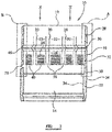
- FIG. 10 there is shown perspective and section views of a centraliser, respectively, generally indicated by reference numeral 10 according to an embodiment of the present disclosure.
- the centraliser 10 is for centralising a tubular (not shown) within a conduit (not shown).
- the centraliser 10 comprises an upper body portion 12, a lower body portion 14 and a plurality of arms 16 linking the upper body portion 12 to the lower body portion 14. As will be discussed, relative movement of the upper body portion 12 towards the lower body portion 14 causes the arms 16 to buckle radially outwards into a set configuration in which the arms 16 are engaged with the conduit (not shown). The centraliser 10 is shown in the set configuration (but not engaged with a conduit) in Figure 5 . The centraliser 10 is adapted to be located around the tubular (not shown). Engagement of the centraliser arms 16 with a conduit centralises the tubular within the conduit.
- the centraliser 10 is machined out of a single length of tubular 18.
- a series of u-shaped slots 20 are made through the wall of the tubular 18 to form a plurality of upper body portion fingers 22.
- Each finger 22 is sandwiched between a pair of arms 16 and has an internal surface 26 defining a ratchet thread 24. The purpose of this internal surface ratchet thread 24 will be described in due course.
- the upper body portion 12 further defines three circumferential grooves 28, 30, 32.
- the upper and lower grooves 28, 34 are defined by a centraliser external surface 34 and the internal groove 30, which is located axially between the external grooves 28, 32, is defined by a centraliser internal surface 36.
- a lower body portion external surface 52 also defines a ratchet thread 38.
- the purpose of this external surface ratchet thread 38 will be described in due course.
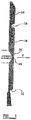
- Figures 3 and 4 these Figures shown an enlarged view of region "A" from Figure 2 and an enlarged view of region "B" from Figure 2 respectively. Particularly, Figure 3 shows a section view through one of the arms 16 and Figure 4 shows a section view through one of the upper body portion fingers 22.
- the lower edge 40 of one of the u-shaped slots 20 is cut such that the bottom 42 of the upper body portion finger 22 is angled, as is the top 44 of the adjacent part of the lower body portion 14.
- the upper body portion fingers 22 move axially towards the lower body portion 14.
- the bottom 42 of each finger 22 comes into contact with the top 44 of the upper body portion 14.
- the angled surfaces provided on the bottom 42 and the top 44 are such that upon impact each finger 22 is deflected outwards, bending about a living hinge 50, provided by the thin wall thickness at the base of the upper groove 28.
- the finger internal surface 26 then passes over the lower body portion external surface 52 and, in particular, the finger internal surface ratchet thread 24 passes over the lower body portion external surface ratchet thread 38.
- ratchet threads 24,38 are arranged such that movement of the fingers 22 in the direction of arrow 'X', that is in the setting direction, is allowed, but movement in the direction opposite arrow 'X', that is opposite the setting direction, is resisted by engagement of the ratchet threads 24,38.
- the setting force continues until the centraliser is in the set configuration shown in Figure 5 .
Landscapes
- Engineering & Computer Science (AREA)
- Geology (AREA)
- Mining & Mineral Resources (AREA)
- Life Sciences & Earth Sciences (AREA)
- General Life Sciences & Earth Sciences (AREA)
- Fluid Mechanics (AREA)
- Environmental & Geological Engineering (AREA)
- Physics & Mathematics (AREA)
- Mechanical Engineering (AREA)
- Geochemistry & Mineralogy (AREA)
- Containers And Packaging Bodies Having A Special Means To Remove Contents (AREA)
- Flexible Shafts (AREA)
- Earth Drilling (AREA)
- Catching Or Destruction (AREA)
- Insulators (AREA)
- Mechanical Pencils And Projecting And Retracting Systems Therefor, And Multi-System Writing Instruments (AREA)
Claims (15)
- Zentrierer (10) zum Zentrieren eines Rohrabschnitts in einer Leitung, wobei der Zentrierer (10) Folgendes umfasst:einen Korpus, der einen oberen Korpusabschnitt (12) und einen unteren Korpusabschnitt (14) umfasst, undmehrere Arme (16), die den oberen Korpusabschnitt (12) mit dem unteren Korpusabschnitt (14) verbinden,wobei eine relative Bewegung des oberen und des unteren Korpusabschnitts (12, 14) zueinander hin bewirkt, dass sich die Arme (16) in Radialrichtung nach außen in eine festgesetzte Konfiguration wölben; unddadurch gekennzeichnet, dassder obere Korpusabschnitt (12) mehrere Finger (22) definiert, welche in Umfangsrichtung zwischen den Armen (16) angeordnet sind und sich in Richtung des unteren Korpusabschnitts (14) erstrecken, wobei die Finger (22) in einer ersten Konfiguration eine nicht-überlappende Konfiguration mit dem unteren Korpusabschnitt (14) definieren, und in der festgesetzten Konfiguration die Finger (22) eine Überlappung mit dem unteren Korpusabschnitt (14) bilden.
- Zentrierer (10) nach Anspruch 1, wobei der Zentrierer (10) röhrenförmig ist.
- Zentrierer (10) nach Anspruch 1 oder 2, wobei eine relative axiale Bewegung der Korpusabschnitte (12, 14) zueinander hin bewirkt, dass sich die Arme (16) in Radialrichtung nach außen wölben.
- Zentrierer (10) nach Anspruch 3, wobei einer der Korpusabschnitte (12, 14) während der relativen axialen Bewegung der Korpusabschnitte (12, 14) zueinander hin unbeweglich bleibt.
- Zentrierer (10) nach Anspruch 3, wobei die axiale Bewegung eines der Korpusabschnitte (12, 14) in einer Einsetzungsrichtung zu dem anderen der Korpusabschnitte (12, 14) hin in einer Einsetzungsrichtung bewirkt, dass sich die Arme (16) in Radialrichtung nach außen wölben.
- Zentrierer (10) nach Anspruch 1 bis 5, wobei das Wölben der Arme (16) nicht umkehrbar ist.
- Zentrierer (10) nach einem der vorhergehenden Ansprüche, wobei mindestens eines von Folgendem zutrifft:wenn sich einer der Korpusabschnitte (12, 14) zu dem anderen der Korpusabschnitte (12; 14) hin bewegt, die Korpusabschnitte (12, 14) einander in Eingriff nehmen;ein Eingriff des oberen und des unteren Korpusabschnitts (12, 14) eine Bewegung des oberen Korpusabschnitts (12) in Bezug auf den unteren Korpusabschnitt (14) in einer Richtung, entgegengesetzt zu der Einsetzungsrichtung, verhindert;der obere und der untere Korpusabschnitt (12, 14) eine Sperrklinke definieren.
- Zentrierer (10) nach einem der vorhergehenden Ansprüche, wobei auf einen Eingriff mit dem unteren Korpusabschnitt (14) hin, jeder Finger (22) des oberen Korpus in Radialrichtung nach außen auslenkt.
- Zentrierer (10) nach einem der vorhergehenden Ansprüche, wobei einer der Abschnitte (12, 14) einen Rohrabschnitt in Eingriff nimmt, auf dem der Zentrierer (10) angeordnet ist, wenn sich die Korpusabschnitte (12, 14) im Verhältnis zueinander bewegen.
- Zentrierer (10) nach Anspruch 9, wobei der Eingriff des Zentrierers (10) und des Rohrabschnitts nicht umkehrbar ist.
- Zentrierer (10) nach einem der vorhergehenden Ansprüche, wobei jeder der mehreren Arme (16) wenigstens einen Schwächepunkt definiert, und wobei wenigstens einer von den Schwächepunkten eine umlaufende Rille (28, 30, 32) ist, die durch den Zentrierer (10) definiert wird.
- Zentrierer (10) nach einem der vorhergehenden Ansprüche, wobei jeder Finger (22) des oberen Korpus in Radialrichtung nach außen um ein Scharnier auslenkt, oder jeder Finger (22) des oberen Korpus in Radialrichtung nach außen um ein Filmscharnier auslenkt.
- Zentrierer (10) nach einem der vorhergehenden Ansprüche, wobei der Zentrierer (10) dafür ausgebildet ist, zwischen benachbarten röhrenförmigen Sektionen angeordnet zu werden.
- Zentrierer (10) nach einem der vorhergehenden Ansprüche, in Kombination mit einer Leitung.
- Verfahren zum Zentrieren eines Rohrabschnitts in einer Leitung, das die folgenden Schritte umfasst:das Bereitstellen eines Korpus, der einen oberen Korpusabschnitt (12) und einen unteren Korpusabschnitt (14) umfasst, und mehrere Arme (16), die den oberen Korpusabschnitt (12) mit dem unteren Korpusabschnitt (14) verbinden, wobei der obere Korpusabschnitt (12) mehrere Finger (22) definiert, welche in Umfangsrichtung zwischen den Armen (16) angeordnet sind und sich in Richtung des unteren Korpusabschnitts (14) erstrecken;das Ausüben einer Einsetzungskraft in einer Einsetzungsrichtung, um den oberen Korpusabschnitt (12) und den unteren Korpusabschnitt (14) zusammenzubewegen;das Wölben der Arme (16), die den oberen Korpusabschnitt (12) mit dem unteren Korpusabschnitt (14) verbinden, in Radialrichtung nach außen in einen Eingriff mit einer Leitungswand; unddas Bewegen der Finger (22) von einer ersten Konfiguration in der die Finger (22) eine nicht-überlappende Konfiguration mit dem unteren Korpusabschnitt (14) definieren, zu einer festgesetzten Konfiguration, in der die Finger (22) eine Überlappung mit dem unteren Korpusabschnitt (14) bilden.
Priority Applications (1)
| Application Number | Priority Date | Filing Date | Title |
|---|---|---|---|
| EP17210228.7A EP3351721B1 (de) | 2007-12-03 | 2008-11-28 | Verbesserter zentrierer |
Applications Claiming Priority (3)
| Application Number | Priority Date | Filing Date | Title |
|---|---|---|---|
| GB0723607A GB0723607D0 (en) | 2007-12-03 | 2007-12-03 | Improved centraliser |
| PCT/GB2008/003957 WO2009071874A2 (en) | 2007-12-03 | 2008-11-28 | Improved centraliser |
| EP20080857410 EP2215324B1 (de) | 2007-12-03 | 2008-11-28 | Verbesserter zentrierer |
Related Parent Applications (2)
| Application Number | Title | Priority Date | Filing Date |
|---|---|---|---|
| EP20080857410 Division EP2215324B1 (de) | 2007-12-03 | 2008-11-28 | Verbesserter zentrierer |
| EP08857410.8 Division | 2008-11-28 |
Related Child Applications (2)
| Application Number | Title | Priority Date | Filing Date |
|---|---|---|---|
| EP17210228.7A Division EP3351721B1 (de) | 2007-12-03 | 2008-11-28 | Verbesserter zentrierer |
| EP17210228.7A Division-Into EP3351721B1 (de) | 2007-12-03 | 2008-11-28 | Verbesserter zentrierer |
Publications (3)
| Publication Number | Publication Date |
|---|---|
| EP2677111A2 EP2677111A2 (de) | 2013-12-25 |
| EP2677111A3 EP2677111A3 (de) | 2016-01-13 |
| EP2677111B1 true EP2677111B1 (de) | 2019-01-09 |
Family
ID=38962517
Family Applications (3)
| Application Number | Title | Priority Date | Filing Date |
|---|---|---|---|
| EP13184205.6A Active EP2677111B1 (de) | 2007-12-03 | 2008-11-28 | Verbesserter Zentrierer |
| EP17210228.7A Active EP3351721B1 (de) | 2007-12-03 | 2008-11-28 | Verbesserter zentrierer |
| EP20080857410 Active EP2215324B1 (de) | 2007-12-03 | 2008-11-28 | Verbesserter zentrierer |
Family Applications After (2)
| Application Number | Title | Priority Date | Filing Date |
|---|---|---|---|
| EP17210228.7A Active EP3351721B1 (de) | 2007-12-03 | 2008-11-28 | Verbesserter zentrierer |
| EP20080857410 Active EP2215324B1 (de) | 2007-12-03 | 2008-11-28 | Verbesserter zentrierer |
Country Status (7)
| Country | Link |
|---|---|
| US (3) | US8555964B2 (de) |
| EP (3) | EP2677111B1 (de) |
| AU (1) | AU2008332956B2 (de) |
| BR (3) | BR122018014772B1 (de) |
| CA (3) | CA2707591C (de) |
| GB (1) | GB0723607D0 (de) |
| WO (1) | WO2009071874A2 (de) |
Families Citing this family (27)
| Publication number | Priority date | Publication date | Assignee | Title |
|---|---|---|---|---|
| GB0723607D0 (en) * | 2007-12-03 | 2008-01-09 | Petrowell Ltd | Improved centraliser |
| NO334036B1 (no) * | 2010-08-06 | 2013-11-25 | Roxar Flow Measurement As | Klemme |
| NL2005866C2 (nl) * | 2010-12-16 | 2012-06-19 | Lankhorst Mouldings B V | Omhullingselement voor een pijpleiding, alsmede matrijs voor vervaardiging daarvan. |
| US9322248B2 (en) | 2010-12-17 | 2016-04-26 | Exxonmobil Upstream Research Company | Wellbore apparatus and methods for multi-zone well completion, production and injection |
| WO2012082303A2 (en) | 2010-12-17 | 2012-06-21 | Exxonmobil Upstream Research Company | Packer for alternate flow channel gravel packing and method for completing a wellbore |
| SG190865A1 (en) | 2010-12-17 | 2013-07-31 | Exxonmobil Upstream Res Co | Crossover joint for connecting eccentric flow paths to concentric flow paths |
| EP2466064A1 (de) * | 2010-12-17 | 2012-06-20 | Welltec A/S | Futterrohranker |
| WO2012082447A1 (en) | 2010-12-17 | 2012-06-21 | Exxonmobil Upstream Research Company | Wellbore apparatus and methods for zonal isolation and flow control |
| US9982496B2 (en) | 2011-07-26 | 2018-05-29 | Innovex Downhole Solutions, Inc. | Rolled tubular centralizer |
| EA030002B1 (ru) | 2012-10-26 | 2018-06-29 | Эксонмобил Апстрим Рисерч Компани | Скважинное устройство и способ борьбы с поступлением песка в скважину с применением гравийного резерва |
| GB2518399B (en) | 2013-09-20 | 2020-04-15 | Equinor Energy As | Method of centralising tubing in a wellbore |
| USD717837S1 (en) | 2014-03-26 | 2014-11-18 | Antelope Oil Tool & Mfg. Co., Llc | One-piece centralizer with an axial seam |
| USD717836S1 (en) | 2014-03-26 | 2014-11-18 | Antelope Oil Tool & Mfg. Co., Llc | One-piece centralizer with an axial seam and end-collar tabs |
| USD718342S1 (en) | 2014-03-26 | 2014-11-25 | Antelope Oil Tool & Mfg. Co., Llc | One-piece centralizer with an axial seam and windows |
| US9670756B2 (en) | 2014-04-08 | 2017-06-06 | Exxonmobil Upstream Research Company | Wellbore apparatus and method for sand control using gravel reserve |
| USD743447S1 (en) | 2014-09-30 | 2015-11-17 | Antelope Tool & Mfg. Co. | Centralizer |
| US10493515B2 (en) | 2015-05-08 | 2019-12-03 | Innovex Downhole Solutions, Inc. | Devices and methods for forming bow springs of one-piece centralizers |
| US11174641B2 (en) | 2016-03-15 | 2021-11-16 | Pieresearch1, LP | Adjustable rebar centralizer for use in a drilled shaft/bore hole |
| US10151113B2 (en) | 2016-03-15 | 2018-12-11 | Pieresearch1, LP | Rebar centralizer for use in a drilled shaft/bore hole |
| US10584459B2 (en) | 2016-03-15 | 2020-03-10 | Pieresearch1, LP | Adjustable rebar centralizer for use in a drilled shaft/bore hole |
| CA3130321A1 (en) * | 2020-09-10 | 2022-03-10 | Harrison Jet Guns II, L.P. | Oilfield perforating self-positioning systems and methods |
| USD992610S1 (en) | 2021-05-10 | 2023-07-18 | Innovex Downhole Solutions, Inc. | Downhole tool including hinges |
| CA230281S (en) * | 2022-03-31 | 2024-06-19 | Reflex Instr Asia Pacific Pty Ltd | A locator for a survey apparatus |
| USD1065994S1 (en) * | 2022-07-29 | 2025-03-11 | Kennametal Inc. | Tool retainer |
| US11898446B1 (en) | 2022-07-29 | 2024-02-13 | Kennametal Inc. | Tool retainer |
| US12270259B2 (en) | 2023-05-18 | 2025-04-08 | Georgia Tech Research Corporation | Snake-skin-inspired in-hole bow spring centralizer |
| USD1099169S1 (en) * | 2024-10-14 | 2025-10-21 | Drillit International Pty Limited | Pipe spacer |
Family Cites Families (72)
| Publication number | Priority date | Publication date | Assignee | Title |
|---|---|---|---|---|
| US643358A (en) | 1899-06-09 | 1900-02-13 | Matthew J Konold | Hose-coupling. |
| US2009322A (en) * | 1934-10-29 | 1935-07-23 | I C Carter | Feather-type valved well packer |
| US2181748A (en) | 1936-05-04 | 1939-11-28 | Guiberson Corp | Plunger |
| US2230447A (en) | 1939-08-26 | 1941-02-04 | Bassinger Ross | Well plug |
| US2311768A (en) * | 1940-11-12 | 1943-02-23 | Mccray George | Casing centering device |
| US2546377A (en) | 1942-01-20 | 1951-03-27 | Lane Wells Co | Bridging plug |
| US2490350A (en) * | 1943-12-15 | 1949-12-06 | Claude C Taylor | Means for centralizing casing and the like in a well |
| US2498791A (en) | 1946-06-22 | 1950-02-28 | James M Clark | Well device |
| US2738018A (en) | 1953-03-12 | 1956-03-13 | Oil Recovery Corp | Oil well treating and production tool |
| GB755082A (en) | 1953-10-12 | 1956-08-15 | Baker Oil Tools Inc | Subsurface well tools |
| US2832418A (en) | 1955-08-16 | 1958-04-29 | Baker Oil Tools Inc | Well packer |
| US2944608A (en) * | 1958-03-25 | 1960-07-12 | Robbins & Myers | Centralizing spider for wells |
| US3066738A (en) | 1958-09-08 | 1962-12-04 | Baker Oil Tools Inc | Well packer and setting device therefor |
| US3167127A (en) | 1961-04-04 | 1965-01-26 | Otis Eng Co | Dual well packer |
| US3087552A (en) | 1961-10-02 | 1963-04-30 | Jersey Prod Res Co | Apparatus for centering well tools in a well bore |
| US3167128A (en) | 1962-04-24 | 1965-01-26 | Wayne N Sutliff | Selective formation zone anchor |
| US3283821A (en) | 1963-12-05 | 1966-11-08 | Cicero C Brown | Screw-set packer |
| US3342268A (en) | 1965-09-07 | 1967-09-19 | Joe R Brown | Well packer for use with high temperature fluids |
| US3371716A (en) | 1965-10-23 | 1968-03-05 | Schlumberger Technology Corp | Bridge plug |
| US3482889A (en) * | 1967-09-18 | 1969-12-09 | Driltrol | Stabilizers for drilling strings |
| GB1257790A (de) | 1967-12-20 | 1971-12-22 | ||
| US3729170A (en) | 1969-02-20 | 1973-04-24 | Hydril Co | Rotary plug valve assembly |
| US3623551A (en) | 1970-01-02 | 1971-11-30 | Schlumberger Technology Corp | Anchoring apparatus for a well packer |
| US3722588A (en) | 1971-10-18 | 1973-03-27 | J Tamplen | Seal assembly |
| GB1364054A (en) | 1972-05-11 | 1974-08-21 | Rees Ltd William F | Centring devices for locating instruments axially within tubular enclosures |
| US4046405A (en) | 1972-05-15 | 1977-09-06 | Mcevoy Oilfield Equipment Co. | Run-in and tie back apparatus |
| US3889750A (en) | 1974-07-17 | 1975-06-17 | Schlumberger Technology Corp | Setting and releasing apparatus for sidewall anchor |
| US4127168A (en) | 1977-03-11 | 1978-11-28 | Exxon Production Research Company | Well packers using metal to metal seals |
| US4127485A (en) * | 1977-07-05 | 1978-11-28 | Baker William H | Vacuum filter for swimming pools |
| US4346919A (en) | 1977-09-15 | 1982-08-31 | Smith International, Inc. | Remote automatic make-up stab-in sealing system |
| US4331315A (en) | 1978-11-24 | 1982-05-25 | Daniel Industries, Inc. | Actuatable safety valve for wells and flowlines |
| US4317485A (en) | 1980-05-23 | 1982-03-02 | Baker International Corporation | Pump catcher apparatus |
| US4375240A (en) | 1980-12-08 | 1983-03-01 | Hughes Tool Company | Well packer |
| FR2525304B1 (fr) | 1982-04-19 | 1988-04-08 | Alsthom Atlantique | Dispositif de securite d'antidevissage |
| US4557327A (en) * | 1983-09-12 | 1985-12-10 | J. C. Kinley Company | Roller arm centralizer |
| US4588030A (en) | 1984-09-27 | 1986-05-13 | Camco, Incorporated | Well tool having a metal seal and bi-directional lock |
| US4794986A (en) * | 1987-11-27 | 1989-01-03 | Weatherford U.S., Inc. | Reticulated centralizing apparatus |
| GB8821982D0 (en) | 1988-09-19 | 1988-10-19 | Cooper Ind Inc | Energisation of sealing assemblies |
| DE3812211A1 (de) | 1988-04-13 | 1989-11-02 | Preussag Ag Bauwesen | Schraubverbindungen fuer steigrohre fuer pumpen in brunnen |
| US4917187A (en) | 1989-01-23 | 1990-04-17 | Baker Hughes Incorporated | Method and apparatus for hydraulically firing a perforating gun below a set packer |
| US5095978A (en) | 1989-08-21 | 1992-03-17 | Ava International | Hydraulically operated permanent type well packer assembly |
| EP0511254B1 (de) | 1990-01-17 | 1995-03-01 | WEATHERFORD/LAMB, INC. (a Delaware Corporation) | Zentriervorrichtung für ölfeldfutterrohr |
| US5029643A (en) | 1990-06-04 | 1991-07-09 | Halliburton Company | Drill pipe bridge plug |
| US5086845A (en) | 1990-06-29 | 1992-02-11 | Baker Hughes Incorporated | Liner hanger assembly |
| US5082061A (en) | 1990-07-25 | 1992-01-21 | Otis Engineering Corporation | Rotary locking system with metal seals |
| GB2248906B (en) | 1990-10-16 | 1994-04-27 | Red Baron | A locking connection |
| US5097905A (en) * | 1991-01-28 | 1992-03-24 | Mobil Oil Corporation | Centralizer for well casing |
| US5542473A (en) | 1995-06-01 | 1996-08-06 | Pringle; Ronald E. | Simplified sealing and anchoring device for a well tool |
| US5575333A (en) * | 1995-06-07 | 1996-11-19 | Weatherford U.S., Inc. | Centralizer |
| US5893589A (en) | 1997-07-07 | 1999-04-13 | Ford Motor Company | Fluid conduit connecting apparatus |
| US5934378A (en) | 1997-08-07 | 1999-08-10 | Computalog Limited | Centralizers for a downhole tool |
| US6062307A (en) | 1997-10-24 | 2000-05-16 | Halliburton Energy Services, Inc. | Screen assemblies and methods of securing screens |
| US6102118A (en) * | 1998-12-30 | 2000-08-15 | Moore; Curt A. | Multi-purpose adjustable centralizer system with tool |
| US6315041B1 (en) | 1999-04-15 | 2001-11-13 | Stephen L. Carlisle | Multi-zone isolation tool and method of stimulating and testing a subterranean well |
| EP2042383B1 (de) | 2000-07-07 | 2011-05-11 | Toyoda Gosei Co., Ltd. | Knieschutz-Airbagvorrichtung |
| US7182131B2 (en) * | 2000-09-06 | 2007-02-27 | Casetech International, Inc. | Dual diameter and rotating centralizer/sub and method |
| US6453998B1 (en) * | 2000-10-31 | 2002-09-24 | Robert W. M. Reeve | Progressive lock integral joint centralizer |
| GB0115704D0 (en) | 2001-06-27 | 2001-08-22 | Winapex Ltd | Centering device |
| US20040055757A1 (en) | 2002-09-24 | 2004-03-25 | Baker Hughes Incorporated | Locking apparatus with packoff capability |
| US6827150B2 (en) | 2002-10-09 | 2004-12-07 | Weatherford/Lamb, Inc. | High expansion packer |
| NO20034158L (no) | 2003-09-18 | 2005-03-21 | Hydralift Asa | Laseanordning av sammenskrudd rorforbindelse |
| US7104318B2 (en) * | 2004-04-07 | 2006-09-12 | Plexus Ocean Systems, Ltd. | Self-contained centralizer system |
| GB0413042D0 (en) | 2004-06-11 | 2004-07-14 | Petrowell Ltd | Sealing system |
| GB0423992D0 (en) | 2004-10-29 | 2004-12-01 | Petrowell Ltd | Improved plug |
| GB0504471D0 (en) | 2005-03-04 | 2005-04-13 | Petrowell Ltd | Improved well bore anchors |
| GB2428708B (en) | 2005-07-30 | 2008-07-23 | Schlumberger Holdings | Rotationally fixable wellbore tubing hanger |
| CA2833612C (en) | 2006-03-23 | 2016-03-08 | Petrowell Limited | Tool with setting force transmission relief device |
| CA2541541A1 (en) | 2006-03-24 | 2007-09-24 | Kenneth H. Wenzel | Apparatus for keeping a down hole drilling tool vertically aligned |
| US7708063B2 (en) * | 2007-02-09 | 2010-05-04 | Baker Hughes Incorporated | Centralizer tool, a centralizing method and a method of making a centralizer tool |
| US7845061B2 (en) * | 2007-05-16 | 2010-12-07 | Frank's International, Inc. | Low clearance centralizer and method of making centralizer |
| GB0723607D0 (en) * | 2007-12-03 | 2008-01-09 | Petrowell Ltd | Improved centraliser |
| EP2604785A1 (de) * | 2008-09-29 | 2013-06-19 | Frank's International, Inc. | Bohrlochvorrichtungsaktuator und Verfahren dafür |
-
2007
- 2007-12-03 GB GB0723607A patent/GB0723607D0/en not_active Ceased
-
2008
- 2008-11-28 CA CA2707591A patent/CA2707591C/en active Active
- 2008-11-28 BR BR122018014772-5A patent/BR122018014772B1/pt active IP Right Grant
- 2008-11-28 BR BRPI0819713A patent/BRPI0819713B1/pt active IP Right Grant
- 2008-11-28 CA CA2927157A patent/CA2927157C/en active Active
- 2008-11-28 WO PCT/GB2008/003957 patent/WO2009071874A2/en not_active Ceased
- 2008-11-28 EP EP13184205.6A patent/EP2677111B1/de active Active
- 2008-11-28 EP EP17210228.7A patent/EP3351721B1/de active Active
- 2008-11-28 CA CA2927001A patent/CA2927001C/en active Active
- 2008-11-28 US US12/743,505 patent/US8555964B2/en active Active
- 2008-11-28 AU AU2008332956A patent/AU2008332956B2/en active Active
- 2008-11-28 BR BR122018014774-1A patent/BR122018014774B1/pt active IP Right Grant
- 2008-11-28 EP EP20080857410 patent/EP2215324B1/de active Active
-
2013
- 2013-09-16 US US14/027,444 patent/US8919437B2/en active Active
-
2014
- 2014-12-23 US US14/580,398 patent/US9932779B2/en active Active
Non-Patent Citations (1)
| Title |
|---|
| None * |
Also Published As
| Publication number | Publication date |
|---|---|
| EP2677111A2 (de) | 2013-12-25 |
| WO2009071874A3 (en) | 2009-07-23 |
| US20140014370A1 (en) | 2014-01-16 |
| WO2009071874A2 (en) | 2009-06-11 |
| AU2008332956A1 (en) | 2009-06-11 |
| CA2707591C (en) | 2017-01-17 |
| US20150122509A1 (en) | 2015-05-07 |
| EP3351721A1 (de) | 2018-07-25 |
| BRPI0819713B1 (pt) | 2019-08-27 |
| BR122018014772B1 (pt) | 2019-06-11 |
| AU2008332956B2 (en) | 2014-10-09 |
| US9932779B2 (en) | 2018-04-03 |
| BR122018014774B1 (pt) | 2019-06-11 |
| EP3351721B1 (de) | 2019-12-25 |
| CA2927001C (en) | 2017-10-31 |
| CA2927157C (en) | 2018-07-03 |
| EP2677111A3 (de) | 2016-01-13 |
| CA2927001A1 (en) | 2009-06-11 |
| US8919437B2 (en) | 2014-12-30 |
| US8555964B2 (en) | 2013-10-15 |
| EP2215324A2 (de) | 2010-08-11 |
| GB0723607D0 (en) | 2008-01-09 |
| EP2215324B1 (de) | 2013-11-06 |
| BRPI0819713A2 (pt) | 2015-06-16 |
| US20110042106A1 (en) | 2011-02-24 |
| CA2707591A1 (en) | 2009-06-11 |
| CA2927157A1 (en) | 2009-06-11 |
Similar Documents
| Publication | Publication Date | Title |
|---|---|---|
| EP2677111B1 (de) | Verbesserter Zentrierer | |
| US10329870B2 (en) | Sealing element backup ring with integrated tab to close extrusion path along a mandrel | |
| EP2185785B1 (de) | Vorrichtung und verfahren zum ausklappen einer an einem spreizbaren futterrohrstrang installierten zentriervorrichtung | |
| DK2971468T3 (en) | FOLDBACK SPLITCHING WITH ANTIOM CORDLINE | |
| JP4559054B2 (ja) | リベット | |
| EP2663727B1 (de) | Zentrierer | |
| US9759023B2 (en) | Apparatus for securing a centralizer to a tubular | |
| US8662161B2 (en) | Expandable packer with expansion induced axially movable support feature | |
| AU2016273992B2 (en) | Open hole expandable packer with extended reach feature | |
| CN1860284B (zh) | 可膨胀的井筒组件 | |
| WO2012115730A2 (en) | Expandable packer with mandrel undercuts and sealing boost feature | |
| US9506315B2 (en) | Open-hole packer | |
| EP3536895A1 (de) | Zentrierer | |
| US7926566B2 (en) | Method of making a downhole cutting tool, using a single piece tubular with a radially displaceable portion | |
| AU697695B2 (en) | Whipstock | |
| AU2014277766B2 (en) | Improved centraliser | |
| AU2016204890B2 (en) | Improved centraliser | |
| EP3752707B1 (de) | Anordnung und verfahren zum durchführen eines ausgerichteten betriebs mit einem im bohrlochrohr orientierten werkzeug | |
| CA2528974C (en) | Method for reducing diameter reduction near ends of expanded tubulars | |
| WO2008040929A1 (en) | Blind rivet |
Legal Events
| Date | Code | Title | Description |
|---|---|---|---|
| PUAI | Public reference made under article 153(3) epc to a published international application that has entered the european phase |
Free format text: ORIGINAL CODE: 0009012 |
|
| 17P | Request for examination filed |
Effective date: 20130912 |
|
| AC | Divisional application: reference to earlier application |
Ref document number: 2215324 Country of ref document: EP Kind code of ref document: P |
|
| AK | Designated contracting states |
Kind code of ref document: A2 Designated state(s): AT BE BG CH CY CZ DE DK EE ES FI FR GB GR HR HU IE IS IT LI LT LU LV MC MT NL NO PL PT RO SE SI SK TR |
|
| PUAL | Search report despatched |
Free format text: ORIGINAL CODE: 0009013 |
|
| AK | Designated contracting states |
Kind code of ref document: A3 Designated state(s): AT BE BG CH CY CZ DE DK EE ES FI FR GB GR HR HU IE IS IT LI LT LU LV MC MT NL NO PL PT RO SE SI SK TR |
|
| RIC1 | Information provided on ipc code assigned before grant |
Ipc: E21B 17/10 20060101AFI20151204BHEP |
|
| STAA | Information on the status of an ep patent application or granted ep patent |
Free format text: STATUS: EXAMINATION IS IN PROGRESS |
|
| 17Q | First examination report despatched |
Effective date: 20170829 |
|
| RAP1 | Party data changed (applicant data changed or rights of an application transferred) |
Owner name: WEATHERFORD TECHNOLOGY HOLDINGS, LLC |
|
| GRAP | Despatch of communication of intention to grant a patent |
Free format text: ORIGINAL CODE: EPIDOSNIGR1 |
|
| STAA | Information on the status of an ep patent application or granted ep patent |
Free format text: STATUS: GRANT OF PATENT IS INTENDED |
|
| INTG | Intention to grant announced |
Effective date: 20180726 |
|
| GRAS | Grant fee paid |
Free format text: ORIGINAL CODE: EPIDOSNIGR3 |
|
| GRAA | (expected) grant |
Free format text: ORIGINAL CODE: 0009210 |
|
| STAA | Information on the status of an ep patent application or granted ep patent |
Free format text: STATUS: THE PATENT HAS BEEN GRANTED |
|
| AC | Divisional application: reference to earlier application |
Ref document number: 2215324 Country of ref document: EP Kind code of ref document: P |
|
| AK | Designated contracting states |
Kind code of ref document: B1 Designated state(s): AT BE BG CH CY CZ DE DK EE ES FI FR GB GR HR HU IE IS IT LI LT LU LV MC MT NL NO PL PT RO SE SI SK TR |
|
| REG | Reference to a national code |
Ref country code: GB Ref legal event code: FG4D |
|
| REG | Reference to a national code |
Ref country code: CH Ref legal event code: EP Ref country code: AT Ref legal event code: REF Ref document number: 1087525 Country of ref document: AT Kind code of ref document: T Effective date: 20190115 |
|
| REG | Reference to a national code |
Ref country code: DE Ref legal event code: R096 Ref document number: 602008058737 Country of ref document: DE |
|
| REG | Reference to a national code |
Ref country code: IE Ref legal event code: FG4D |
|
| REG | Reference to a national code |
Ref country code: NL Ref legal event code: FP |
|
| REG | Reference to a national code |
Ref country code: LT Ref legal event code: MG4D |
|
| REG | Reference to a national code |
Ref country code: NO Ref legal event code: T2 Effective date: 20190109 |
|
| REG | Reference to a national code |
Ref country code: AT Ref legal event code: MK05 Ref document number: 1087525 Country of ref document: AT Kind code of ref document: T Effective date: 20190109 |
|
| PG25 | Lapsed in a contracting state [announced via postgrant information from national office to epo] |
Ref country code: LT Free format text: LAPSE BECAUSE OF FAILURE TO SUBMIT A TRANSLATION OF THE DESCRIPTION OR TO PAY THE FEE WITHIN THE PRESCRIBED TIME-LIMIT Effective date: 20190109 Ref country code: FI Free format text: LAPSE BECAUSE OF FAILURE TO SUBMIT A TRANSLATION OF THE DESCRIPTION OR TO PAY THE FEE WITHIN THE PRESCRIBED TIME-LIMIT Effective date: 20190109 Ref country code: PT Free format text: LAPSE BECAUSE OF FAILURE TO SUBMIT A TRANSLATION OF THE DESCRIPTION OR TO PAY THE FEE WITHIN THE PRESCRIBED TIME-LIMIT Effective date: 20190509 Ref country code: ES Free format text: LAPSE BECAUSE OF FAILURE TO SUBMIT A TRANSLATION OF THE DESCRIPTION OR TO PAY THE FEE WITHIN THE PRESCRIBED TIME-LIMIT Effective date: 20190109 Ref country code: SE Free format text: LAPSE BECAUSE OF FAILURE TO SUBMIT A TRANSLATION OF THE DESCRIPTION OR TO PAY THE FEE WITHIN THE PRESCRIBED TIME-LIMIT Effective date: 20190109 Ref country code: PL Free format text: LAPSE BECAUSE OF FAILURE TO SUBMIT A TRANSLATION OF THE DESCRIPTION OR TO PAY THE FEE WITHIN THE PRESCRIBED TIME-LIMIT Effective date: 20190109 |
|
| PG25 | Lapsed in a contracting state [announced via postgrant information from national office to epo] |
Ref country code: HR Free format text: LAPSE BECAUSE OF FAILURE TO SUBMIT A TRANSLATION OF THE DESCRIPTION OR TO PAY THE FEE WITHIN THE PRESCRIBED TIME-LIMIT Effective date: 20190109 Ref country code: IS Free format text: LAPSE BECAUSE OF FAILURE TO SUBMIT A TRANSLATION OF THE DESCRIPTION OR TO PAY THE FEE WITHIN THE PRESCRIBED TIME-LIMIT Effective date: 20190509 Ref country code: LV Free format text: LAPSE BECAUSE OF FAILURE TO SUBMIT A TRANSLATION OF THE DESCRIPTION OR TO PAY THE FEE WITHIN THE PRESCRIBED TIME-LIMIT Effective date: 20190109 Ref country code: BG Free format text: LAPSE BECAUSE OF FAILURE TO SUBMIT A TRANSLATION OF THE DESCRIPTION OR TO PAY THE FEE WITHIN THE PRESCRIBED TIME-LIMIT Effective date: 20190409 Ref country code: GR Free format text: LAPSE BECAUSE OF FAILURE TO SUBMIT A TRANSLATION OF THE DESCRIPTION OR TO PAY THE FEE WITHIN THE PRESCRIBED TIME-LIMIT Effective date: 20190410 |
|
| REG | Reference to a national code |
Ref country code: DE Ref legal event code: R097 Ref document number: 602008058737 Country of ref document: DE |
|
| PG25 | Lapsed in a contracting state [announced via postgrant information from national office to epo] |
Ref country code: AT Free format text: LAPSE BECAUSE OF FAILURE TO SUBMIT A TRANSLATION OF THE DESCRIPTION OR TO PAY THE FEE WITHIN THE PRESCRIBED TIME-LIMIT Effective date: 20190109 Ref country code: CZ Free format text: LAPSE BECAUSE OF FAILURE TO SUBMIT A TRANSLATION OF THE DESCRIPTION OR TO PAY THE FEE WITHIN THE PRESCRIBED TIME-LIMIT Effective date: 20190109 Ref country code: RO Free format text: LAPSE BECAUSE OF FAILURE TO SUBMIT A TRANSLATION OF THE DESCRIPTION OR TO PAY THE FEE WITHIN THE PRESCRIBED TIME-LIMIT Effective date: 20190109 Ref country code: SK Free format text: LAPSE BECAUSE OF FAILURE TO SUBMIT A TRANSLATION OF THE DESCRIPTION OR TO PAY THE FEE WITHIN THE PRESCRIBED TIME-LIMIT Effective date: 20190109 Ref country code: EE Free format text: LAPSE BECAUSE OF FAILURE TO SUBMIT A TRANSLATION OF THE DESCRIPTION OR TO PAY THE FEE WITHIN THE PRESCRIBED TIME-LIMIT Effective date: 20190109 Ref country code: DK Free format text: LAPSE BECAUSE OF FAILURE TO SUBMIT A TRANSLATION OF THE DESCRIPTION OR TO PAY THE FEE WITHIN THE PRESCRIBED TIME-LIMIT Effective date: 20190109 |
|
| PLBE | No opposition filed within time limit |
Free format text: ORIGINAL CODE: 0009261 |
|
| STAA | Information on the status of an ep patent application or granted ep patent |
Free format text: STATUS: NO OPPOSITION FILED WITHIN TIME LIMIT |
|
| 26N | No opposition filed |
Effective date: 20191010 |
|
| PGFP | Annual fee paid to national office [announced via postgrant information from national office to epo] |
Ref country code: DE Payment date: 20191112 Year of fee payment: 12 |
|
| PG25 | Lapsed in a contracting state [announced via postgrant information from national office to epo] |
Ref country code: SI Free format text: LAPSE BECAUSE OF FAILURE TO SUBMIT A TRANSLATION OF THE DESCRIPTION OR TO PAY THE FEE WITHIN THE PRESCRIBED TIME-LIMIT Effective date: 20190109 |
|
| PGFP | Annual fee paid to national office [announced via postgrant information from national office to epo] |
Ref country code: IT Payment date: 20191108 Year of fee payment: 12 Ref country code: FR Payment date: 20191014 Year of fee payment: 12 |
|
| PG25 | Lapsed in a contracting state [announced via postgrant information from national office to epo] |
Ref country code: TR Free format text: LAPSE BECAUSE OF FAILURE TO SUBMIT A TRANSLATION OF THE DESCRIPTION OR TO PAY THE FEE WITHIN THE PRESCRIBED TIME-LIMIT Effective date: 20190109 |
|
| REG | Reference to a national code |
Ref country code: CH Ref legal event code: PL |
|
| PG25 | Lapsed in a contracting state [announced via postgrant information from national office to epo] |
Ref country code: LI Free format text: LAPSE BECAUSE OF NON-PAYMENT OF DUE FEES Effective date: 20191130 Ref country code: LU Free format text: LAPSE BECAUSE OF NON-PAYMENT OF DUE FEES Effective date: 20191128 Ref country code: MC Free format text: LAPSE BECAUSE OF FAILURE TO SUBMIT A TRANSLATION OF THE DESCRIPTION OR TO PAY THE FEE WITHIN THE PRESCRIBED TIME-LIMIT Effective date: 20190109 Ref country code: CH Free format text: LAPSE BECAUSE OF NON-PAYMENT OF DUE FEES Effective date: 20191130 |
|
| REG | Reference to a national code |
Ref country code: BE Ref legal event code: MM Effective date: 20191130 |
|
| REG | Reference to a national code |
Ref country code: NL Ref legal event code: RC Free format text: DETAILS LICENCE OR PLEDGE: RIGHT OF PLEDGE, ESTABLISHED Name of requester: DEUTSCHE BANK TRUST COMPANY AMERICAS Effective date: 20200723 |
|
| REG | Reference to a national code |
Ref country code: GB Ref legal event code: 732E Free format text: REGISTERED BETWEEN 20200813 AND 20200819 |
|
| PG25 | Lapsed in a contracting state [announced via postgrant information from national office to epo] |
Ref country code: IE Free format text: LAPSE BECAUSE OF NON-PAYMENT OF DUE FEES Effective date: 20191128 |
|
| PG25 | Lapsed in a contracting state [announced via postgrant information from national office to epo] |
Ref country code: BE Free format text: LAPSE BECAUSE OF NON-PAYMENT OF DUE FEES Effective date: 20191130 |
|
| REG | Reference to a national code |
Ref country code: GB Ref legal event code: 732E Free format text: REGISTERED BETWEEN 20201126 AND 20201202 |
|
| REG | Reference to a national code |
Ref country code: GB Ref legal event code: 732E Free format text: REGISTERED BETWEEN 20210225 AND 20210303 |
|
| PG25 | Lapsed in a contracting state [announced via postgrant information from national office to epo] |
Ref country code: CY Free format text: LAPSE BECAUSE OF FAILURE TO SUBMIT A TRANSLATION OF THE DESCRIPTION OR TO PAY THE FEE WITHIN THE PRESCRIBED TIME-LIMIT Effective date: 20190109 |
|
| REG | Reference to a national code |
Ref country code: DE Ref legal event code: R119 Ref document number: 602008058737 Country of ref document: DE |
|
| PG25 | Lapsed in a contracting state [announced via postgrant information from national office to epo] |
Ref country code: MT Free format text: LAPSE BECAUSE OF FAILURE TO SUBMIT A TRANSLATION OF THE DESCRIPTION OR TO PAY THE FEE WITHIN THE PRESCRIBED TIME-LIMIT Effective date: 20190109 Ref country code: HU Free format text: LAPSE BECAUSE OF FAILURE TO SUBMIT A TRANSLATION OF THE DESCRIPTION OR TO PAY THE FEE WITHIN THE PRESCRIBED TIME-LIMIT; INVALID AB INITIO Effective date: 20081128 |
|
| PG25 | Lapsed in a contracting state [announced via postgrant information from national office to epo] |
Ref country code: IT Free format text: LAPSE BECAUSE OF NON-PAYMENT OF DUE FEES Effective date: 20201128 Ref country code: FR Free format text: LAPSE BECAUSE OF NON-PAYMENT OF DUE FEES Effective date: 20201130 |
|
| PG25 | Lapsed in a contracting state [announced via postgrant information from national office to epo] |
Ref country code: DE Free format text: LAPSE BECAUSE OF NON-PAYMENT OF DUE FEES Effective date: 20210601 |
|
| P01 | Opt-out of the competence of the unified patent court (upc) registered |
Effective date: 20230922 |
|
| PGFP | Annual fee paid to national office [announced via postgrant information from national office to epo] |
Ref country code: GB Payment date: 20250930 Year of fee payment: 18 |
|
| PGFP | Annual fee paid to national office [announced via postgrant information from national office to epo] |
Ref country code: NL Payment date: 20251003 Year of fee payment: 18 |
|
| PGFP | Annual fee paid to national office [announced via postgrant information from national office to epo] |
Ref country code: NO Payment date: 20251113 Year of fee payment: 18 |