EP2677171A2 - Windkraftanlage mit einem zwischen Planetengetriebe und Generator angeordneten Kupplunsmittel zum Ausgleich von Axial, Radial- uns Winkelversatz - Google Patents
Windkraftanlage mit einem zwischen Planetengetriebe und Generator angeordneten Kupplunsmittel zum Ausgleich von Axial, Radial- uns Winkelversatz Download PDFInfo
- Publication number
- EP2677171A2 EP2677171A2 EP13002852.5A EP13002852A EP2677171A2 EP 2677171 A2 EP2677171 A2 EP 2677171A2 EP 13002852 A EP13002852 A EP 13002852A EP 2677171 A2 EP2677171 A2 EP 2677171A2
- Authority
- EP
- European Patent Office
- Prior art keywords
- generator
- shaft
- coupling means
- wind turbine
- planetary gear
- Prior art date
- Legal status (The legal status is an assumption and is not a legal conclusion. Google has not performed a legal analysis and makes no representation as to the accuracy of the status listed.)
- Granted
Links
Images



Classifications
-
- F—MECHANICAL ENGINEERING; LIGHTING; HEATING; WEAPONS; BLASTING
- F03—MACHINES OR ENGINES FOR LIQUIDS; WIND, SPRING, OR WEIGHT MOTORS; PRODUCING MECHANICAL POWER OR A REACTIVE PROPULSIVE THRUST, NOT OTHERWISE PROVIDED FOR
- F03D—WIND MOTORS
- F03D15/00—Transmission of mechanical power
-
- F—MECHANICAL ENGINEERING; LIGHTING; HEATING; WEAPONS; BLASTING
- F03—MACHINES OR ENGINES FOR LIQUIDS; WIND, SPRING, OR WEIGHT MOTORS; PRODUCING MECHANICAL POWER OR A REACTIVE PROPULSIVE THRUST, NOT OTHERWISE PROVIDED FOR
- F03D—WIND MOTORS
- F03D15/00—Transmission of mechanical power
- F03D15/20—Gearless transmission, i.e. direct-drive
-
- F—MECHANICAL ENGINEERING; LIGHTING; HEATING; WEAPONS; BLASTING
- F16—ENGINEERING ELEMENTS AND UNITS; GENERAL MEASURES FOR PRODUCING AND MAINTAINING EFFECTIVE FUNCTIONING OF MACHINES OR INSTALLATIONS; THERMAL INSULATION IN GENERAL
- F16H—GEARING
- F16H1/00—Toothed gearings for conveying rotary motion
- F16H1/28—Toothed gearings for conveying rotary motion with gears having orbital motion
- F16H1/48—Special means compensating for misalignment of axes, e.g. for equalising distribution of load on the face width of the teeth
-
- F—MECHANICAL ENGINEERING; LIGHTING; HEATING; WEAPONS; BLASTING
- F05—INDEXING SCHEMES RELATING TO ENGINES OR PUMPS IN VARIOUS SUBCLASSES OF CLASSES F01-F04
- F05B—INDEXING SCHEME RELATING TO WIND, SPRING, WEIGHT, INERTIA OR LIKE MOTORS, TO MACHINES OR ENGINES FOR LIQUIDS COVERED BY SUBCLASSES F03B, F03D AND F03G
- F05B2260/00—Function
- F05B2260/40—Transmission of power
- F05B2260/403—Transmission of power through the shape of the drive components
- F05B2260/4031—Transmission of power through the shape of the drive components as in toothed gearing
- F05B2260/40311—Transmission of power through the shape of the drive components as in toothed gearing of the epicyclic, planetary or differential type
-
- F—MECHANICAL ENGINEERING; LIGHTING; HEATING; WEAPONS; BLASTING
- F16—ENGINEERING ELEMENTS AND UNITS; GENERAL MEASURES FOR PRODUCING AND MAINTAINING EFFECTIVE FUNCTIONING OF MACHINES OR INSTALLATIONS; THERMAL INSULATION IN GENERAL
- F16D—COUPLINGS FOR TRANSMITTING ROTATION; CLUTCHES; BRAKES
- F16D3/00—Yielding couplings, i.e. with means permitting movement between the connected parts during the drive
- F16D3/16—Universal joints in which flexibility is produced by means of pivots or sliding or rolling connecting parts
-
- Y—GENERAL TAGGING OF NEW TECHNOLOGICAL DEVELOPMENTS; GENERAL TAGGING OF CROSS-SECTIONAL TECHNOLOGIES SPANNING OVER SEVERAL SECTIONS OF THE IPC; TECHNICAL SUBJECTS COVERED BY FORMER USPC CROSS-REFERENCE ART COLLECTIONS [XRACs] AND DIGESTS
- Y02—TECHNOLOGIES OR APPLICATIONS FOR MITIGATION OR ADAPTATION AGAINST CLIMATE CHANGE
- Y02E—REDUCTION OF GREENHOUSE GAS [GHG] EMISSIONS, RELATED TO ENERGY GENERATION, TRANSMISSION OR DISTRIBUTION
- Y02E10/00—Energy generation through renewable energy sources
- Y02E10/70—Wind energy
- Y02E10/72—Wind turbines with rotation axis in wind direction
Definitions
- the present invention relates to a wind turbine with a planetary gear, which is arranged for converting a slow rotational movement of a rotor into a fast rotary motion for operating an integrated medium-speed electric generator, comprising a gear input shaft indirectly connected to the rotor and indirectly connected via a generator shaft to the generator Transmission output shaft, wherein between the generator and the planetary gear, a coupling means is arranged.
- the field of application of the invention extends to planetary gears as they occur in the drive train of a wind turbine.
- Important features of such planetary gear include dimensions and weight. It depends on the design of the gear parts in addition to the selection of materials and the constructive aspects of the prevailing forces and torques, which act on the planetary gear.
- Such planetary gears are subject to extraordinary stresses, which are caused due to their structural position and the unevenly changing load collective.
- the transmission which is usually a multi-stage planetary gear with spur gears
- the generator are separately elevated and each have their own housing. Connected to the output shaft of the transmission and the output shaft of the high-speed generator by an intermediate shaft.
- Medium-speed drive trains with few spur gears are already known from the prior art. If only planetary stages are used, the sun gear shaft of the generator-side planetary stage can serve as a connection shaft to the generator.
- a planetary gear set for converting a slow rotational motion of a rotor into a fast rotational motion for operating an integrated medium-speed electric generator.
- the transmission and the generator are arranged coaxially and have a common mounting of the transmission output shaft and the generator drive shaft.
- a clutch is arranged in radial alignment with the bearing.
- the forces generated by the rotor and the generator on the aforementioned bearing are smaller than the static and dynamic torques through the teeth. It would be more advantageous to avoid a common bearing of coaxial output shaft and generator shaft.
- the coupling means is arranged to compensate for axial, radial and angular misalignment between the planetary gear and the generator shaft.
- Such an arrangement in combination with a suitable coupling means effectively compensates for forces and moments caused by axial, radial and angular misalignment, so that only the torsional moment is transmitted from the planetary gear to the generator. This allows due to the force acting on the generator lower force collective, a corresponding weight-optimized design of the generator.
- the coupling means is arranged between a generator shaft and a sun gear of the planetary gear Doppelkardanisch mounted transmission output shaft.
- the gear side serves as the sun gear as articulation points and the generator side, the generator shaft serves as a point of articulation.
- the Doppelkardanische bearing of the transmission output shaft allows the compensation of axial, radial and angular offset between planetary gear and generator.
- the coupling means is arranged between the planetary gear and the generator shaft designed as Clarradwelle generator side gimbal mounted gearbox output shaft.
- the gearbox output shaft should have a corresponding length.
- the length of the transmission output shaft corresponds to at least twice a diameter of the transmission output shaft. The radial offset can then be compensated for the appropriate length by the angular offset, the axial offset can be compensated by the gimbal bearing.
- the coupling means is arranged on the generator side to a arranged between the planetary gear and generator shaft designed as a sun gear shaft gearbox output shaft with gear-side running gear teeth.
- the generator-side coupling means preferably comprises at least one double-plate clutch, at least one torsionally rigid toothed coupling and / or at least one torsionally and flexurally elastic tab coupling.
- a coupling agent or more coupling means can be connected in series one behind the other.
- a combination of the aforementioned coupling agents is also conceivable.
- the generator-side coupling means is flanged to the sun gear, wherein between the flanged coupling means and the sun gear shaft, a positive or non-positive connection is provided.
- a positive or non-positive connection is provided between the flanged coupling means and the sun gear shaft.
- friction-increasing agents are friction-increasing films and friction-increasing coatings, wherein these in the Typically have hard particles that partially penetrate each other in the end surfaces when compressing the two end faces and create a microforming.
- a generator-side coupling flange is forged on the sun gear shaft.
- a lubricant requiring coupling with gear oil for lubrication and cooling can be supplied, wherein the lubricant requiring coupling means is sealed to the generator by a sealing element oil-tight. If the coupling agent requires no lubrication, a sealing of the generator from the transmission by the sealing element is advantageous.
- the invention includes the technical teaching that the coupling agent is current-insulating or at least current-insulating agent.
- the coupling agent is current-insulating or at least current-insulating agent.
- ceramic and polymer elements, but especially glass fiber and carbon elements are suitable.
- the screw can have current-insulating bushes and / or current-insulating washers.
- a current-insulating intermediate shaft, in particular a Doppelkardanisch mounted output shaft, from the said materials conceivable.
- FIG. 1 shows a side view of a wind turbine 1 with its essential components.
- the wind turbine 1 has a tower 14, on which a gondola 15 rotatably mounted about a vertical axis is arranged in the form of a machine housing.
- a planetary gear 2 is rotatably mounted, which has a transmission input shaft 5 and a transmission output shaft 7.
- the transmission input shaft 5 is connected to a hub 16 of a rotor 3 having a plurality of rotor blades 17.
- the transmission output shaft 7 is rotatably connected to a drive device to be driven in the form of a generator 4.
- the planetary gear 2 is designed so that it converts a slow rotational movement of the transmission input shaft 5 in a fast rotational movement of the transmission output shaft 7.
- the planetary gear 2 has two or more planetary gear stages, which interact with the transmission output shaft 7 via a final spur gear.
- electrical energy is generated by the offset from the wind in rotation rotor 3 initiates the rotational movement of the transmission input shaft 5 in the planetary gear 2.
- the planetary gear 2 converts the rotational movement into a faster rotational movement and finally the fast rotational movement for generating power is transmitted to the generator 4 via the transmission output shaft 7.
- FIG. 2 is a flanged to a transmission housing 18 of the planetary gear 2 generator housing 19 of the generator 4 to see.
- a Doppelkardanisch mounted gearbox output shaft 7 serves as a coupling means between the generator shaft 6, which is mounted on the generator housing 19 via bearings 21, and a sun gear 8 of the planetary gear 2.
- the transmission output shaft 7 thus has on the sun gear 8 and the generator shaft 6 each have a joint 20 , so that the gear side, the sun gear 8 serves as a point of articulation and generator side, the generator shaft 6 serves as a point of articulation. Over here, the compensation of axial, radial and angular offset between planetary gear 2 and generator 4 takes place.
- the transmission output shaft 7 thus has only one joint 20, which is arranged on the inner peripheral surface of the generator shaft 6. Furthermore, the transmission output shaft 7 has a corresponding length, so that the radial offset is compensated by the angular offset and the axial offset is compensated by the gimbal bearing.
- the coupling means is arranged on the generator side to the transmission output shaft 7. Further, the transmission output shaft 7 formed as a sun gear shaft 9 is disposed between the planetary gear 2 and the generator shaft 6. The generator-facing end of the sun gear 9 is formed to a coupling flange 13. As a coupling means a double lamella coupling 10 is arranged on the end face of the coupling flange 13. Likewise, the arrangement of a toothed coupling 11 and / or a tab coupling 12 would be possible at the same position. Radially between an outer periphery of the sun gear 9 and the gear housing 18, a sealing member 22 is arranged, which seals the generator 4 from the gear 2 oil-tight.
Landscapes
- Engineering & Computer Science (AREA)
- General Engineering & Computer Science (AREA)
- Mechanical Engineering (AREA)
- Life Sciences & Earth Sciences (AREA)
- Sustainable Development (AREA)
- Sustainable Energy (AREA)
- Chemical & Material Sciences (AREA)
- Combustion & Propulsion (AREA)
- Wind Motors (AREA)
- Retarders (AREA)
Abstract
Description
- Die vorliegende Erfindung betrifft eine Windkraftanlage mit einem Planetengetriebe, welches zur Umwandelung einer langsamen Drehbewegung eines Rotors in eine schnelle Drehbewegung zum Betrieb eines integrierten mittellschnelllaufenden elektrischen Generators angeordnet ist, umfassend eine mittelbar mit dem Rotor verbundene Getriebeantriebswelle und eine mittelbar über eine Generatorwelle mit dem Generator verbundene Getriebeabtriebswelle, wobei zwischen dem Generator und dem Planetengetriebe ein Kupplungsmittel angeordnet ist.
- Das Anwendungsgebiet der Erfindung erstreckt sich auf Planetengetriebe wie sie im Antriebsstrang einer Windkraftanlage vorkommen. Wichtige Merkmale solcher Planetengetriebe sind unter anderem die Abmessungen und das Gewicht. Dabei kommt es bei der Auslegung der Getriebeteile neben der Werkstoffauswahl und den konstruktiven Aspekten auch auf die herrschenden Kräfte und Drehmomente an, welche auf das Planetengetriebe wirken. Derartige Planetengetriebe unterliegen außergewöhnlichen Beanspruchungen, die aufgrund ihrer baulichen Lage und dem ungleichmäßig wechselndem Belastungskollektivs hervorgerufen werden.
- Aus der
DE 10 2006 051 546 A1 geht unter anderem eine Windenergieanlage mit einem doppelgespeisten Asynchrongenerator hervor, wobei zwischen dem Asynchrongenerator und einem Getriebe eine Kupplung vorgesehen ist. Diese Kupplung dient dazu, den Generator mechanisch vom Triebstrang zu trennen, so dass während eines Phasenschieberbetriebes das Getriebe und der Asynchrongenerator voneinander entkoppelt sind. Die zur Aufrechterhaltung der Drehzahl notwendige Wirkleistung entspricht lediglich den Verlusten im Generator und Umrichter. - Aus dem allgemein bekannten Stand der Technik geht hervor, dass im aufgelösten Antriebstrang das Getriebe, welches in der Regel ein mehrstufiges Planetengetriebe mit Stirnradstufen ist, und der Generator getrennt voneinander aufgeständert sind und jeweils ein eigenes Gehäuse aufweisen. Verbunden werden die Abtriebswelle des Getriebes und die Abtriebswelle des schnelldrehenden Generators durch eine Zwischenwelle. Mittelschnell laufende Antriebsstränge mit wenigen Stirnradstufen gibt sind bereits aus dem Stand der Technik bekannt. Falls nur Planetenstufen verwendet werden, kann die Sonnenradwelle der generatorseitigen Planetenstufe als Verbindungswelle zum Generator dienen.
- Aus der
US 80,75,442 B2 geht ein Planetengetriebe zur Umwandlung einer langsamen Drehbewegung eines Rotors in eine schnelle Drehbewegung zum Betrieb eines integrierten mittelschnelllaufenden elektrischen Generators hervor. Das Getriebe und der Generator sind koaxial angeordnet und weisen eine gemeinsame Lagerung der Getriebeabtriebswelle und der Generatorantriebswelle auf. Zwischen dem Generator und dem Getriebe ist eine Kupplung in radialer Fluchtung mit dem Lager angeordnet. Zudem sind die durch den Rotor und den Generator erzeugten Kräfte auf das zuvor genannte Lager kleiner als die statischen und dynamischen Drehmomente durch die Verzahnung. Vorteilhafter wäre es, ein gemeinsames Lager von koaxialer Abtriebswelle und Generatorwelle zu vermeiden. - Des Weiteren geht aus dem allgemein bekannten Stand der Technik hervor, dass bei mittelschnelllaufenden Getrieben mit direkt angeflanschtem Generator das Ziel möglichst kurz zu bauen im Vordergrund steht. Das Gehäuse des Getriebes kann gleichzeitig das Gehäuse des Generators darstellen, so dass das Getriebe und der Generator aneinander angeflanscht sind. Diese Bauweise ist derart kompakt, dass die Abtriebswelle des Getriebes meistens unmittelbar den Generator antreibt. Da es im integrierten Antriebsstrang zwischen Getriebe und Generator zu Axial-, Radialversatz und Winkelfehlstellungen kommen kann, welche durch Fertigungs- und Montagetoleranzen, aber auch Unwuchten und lastabhängigen Verformungen hervorgerufen werden können, ist es sinnvoll, diese zu kompensieren, um möglichst nur das Torsionsmoment zu übertragen.
- Es ist daher die Aufgabe der vorliegenden Erfindung, eine Windkraftanlage, insbesondere den Antriebsstrang einer Windkraftanlage, umfassend einem Planetengetriebe und einem integrierten mittellschnelllaufenden elektrischen Generator bereitzustellen, welcher durch Axial-, Radial- und Winkelversatz hervorgerufene Kräfte und Momente kompensiert, um nur das Torsionsmoment zu übertragen.
- Die Aufgabe wird ausgehend von einer Windkraftanlage gemäß dem Oberbegriff von Anspruch 1 in Verbindung mit dessen kennzeichnenden Merkmalen gelöst. Vorteilhafte Weiterbildungen der Erfindung gehen aus den nachfolgenden abhängigen Ansprüchen hervor.
- Erfindungsgemäß ist das Kupplungsmittel zum Ausgleich von Axial-, Radial- und Winkelversatz zwischen dem Planetengetriebe und der Generatorwelle angeordnet. Eine derartige Anordnung in Verbindung mit einem geeigneten Kupplungsmittel kompensiert durch Axial-, Radial- und Winkelversatz hervorgerufene Kräfte und Momente wirksam, so dass nur noch das Torsionsmoment vom Planetengetriebe auf den Generator übertragen wird. Dies erlaubt aufgrund des auf den Generator wirkenden geringeren Kräftekollektivs, eine dementsprechende gewichtsoptimierte Konstruktion des Generators.
- Gemäß einer bevorzugten Ausführungsform ist das Kupplungsmittel eine zwischen einer Generatorwelle und einem Sonnenrad des Planetengetriebes angeordnete doppelkardanisch gelagerte Getriebeabtriebswelle. Dabei dient getriebeseitig das Sonnenrad als Anlenkpunkte und generatorseitig dient die Generatorwelle als Anlenkpunkt. Die doppelkardanische Lagerung der Getriebeabtriebswelle ermöglicht die Kompensation von Axial-, Radial- und Winkelversatz zwischen Planetengetriebe und Generator.
- Gemäß einer zweiten bevorzugten Ausführungsform ist das Kupplungsmittel eine zwischen Planetengetriebe und Generatorwelle angeordnete als Sonnenradwelle ausgebildete generatorseitig kardanisch gelagerte Getriebeabtriebswelle. Um wie zuvor Axial-, Radial- und Winkelversatz zwischen Planetengetriebe und Generator zu kompensieren, sollte die Getriebeabtriebswelle eine entsprechende Länge aufweisen. Vorzugsweise entspricht die Länge der Getriebeabtriebswelle mindestens dem Doppelten eines Durchmessers der Getriebeabtriebswelle. Der Radialversatz kann dann bei entsprechender Länge durch den Winkelversatz kompensiert werden, wobei der Axialversatz durch die kardanische Lagerung kompensierbar ist.
- Gemäß einer dritten bevorzugten Ausführungsform ist das Kupplungsmittel generatorseitig an eine zwischen Planetengetriebe und Generatorwelle angeordnete als Sonnenradwelle ausgebildete Getriebeabtriebswelle mit getriebeseitiger Laufverzahnung angeordnet. Eine derartige Ausführungsform ermöglicht eine Bauraum einsparende, den Antriebsstrang verkürzende Lösung. Das generatorseitige Kupplungsmittel umfasst bevorzugt mindestens eine Doppellamellenkupplung, mindestens eine drehsteife Zahnkupplung und/oder mindestens eine dreh- und biegeelastische Laschenkupplung. Zur Kompensation von Axial-, Radial- und Winkelversatz zwischen Planetengetriebe und Generator kann entweder ein Kupplungsmittel oder mehrere Kupplungsmittel hintereinander in Reihe geschaltet werden. Eine Kombination der zuvor genannten Kupplungsmittel ist ebenfalls denkbar.
- Es wird weiterhin vorgeschlagen, dass das generatorseitige Kupplungsmittel an der Sonnenradwelle angeflanscht ist, wobei zwischen dem angeflanschten Kupplungsmittel und der Sonnenradwelle eine form- oder kraftschlüssige Verbindung vorgesehen ist. So ist es beispielsweise möglich die axiale Stirnfläche der Sonnenradwelle und die axiale Stirnfläche des Kupplungsmittels in Kontakt zu bringen, um sie dann über Verbindungsmittel, insbesondere Schrauben- oder Bolzenelemente, formschlüssig miteinander zu verbinden.
- Vorzugsweise sind bei der kraftschlüssigen Verbindung zwischen dem angeflanschten Kupplungsmittel und der Sonnenradwelle axial an den Stirnflächen der Verbindungsstellen reibwerterhöhende Mittel vorgesehen. Dadurch wird der Reibwert an den besagten Stellen erhöht und der Kraftschluss verstärkt. Besonders geeignete reibwerterhöhende Mittel stellen reibwerterhöhende Folien und reibwerterhöhende Beschichtungen dar, wobei diese in der Regel Hartpartikel aufweisen, die beim zusammenpressen der beiden Stirnflächen aneinander teilweise in die Stirnflächen eindringen und einen Mikroformschluss erzeugen.
- Gemäß einer die Erfindung weiter verbessernden Maßnahme wird vorgeschlagen, dass ein generatorseitiger Kupplungsflansch an der Sonnenradwelle angeschmiedet ist. Das direkte Anschmieden des Kupplungsflansches an die Sonnenradwelle, bzw. das Ausbilden des zum Generator gerichteten Ende der Stirnradwelle zum Flansch erfordert zwar ein daran speziell angepasstes Kupplungsmittel, realisiert aber eine verbesserte Verbindungsmöglichkeit zwischen Sonnenradwelle und Kupplungsmittel.
- Es wird weiterhin vorgeschlagen, dass ein schmierungsbedürftiges Kupplungsmittel mit Getriebeöl zur Schmierung und Kühlung versorgbar ist, wobei das schmierungsbedürftige Kupplungsmittel gegenüber dem Generator durch ein Dichtungselement öldicht abgedichtet ist. Sofern das Kupplungsmittel keiner Schmierung bedarf, ist eine Abdichtung des Generators vom Getriebe durch das Dichtungselement vorteilhaft.
- Die Erfindung schließt die technische Lehre ein, dass das Kupplungsmittel stromisolierend ist oder zumindest stromisolierende Mittel aufweist. Dazu eignen sich Keramik- und Polymerelemente, insbesondere aber Glasfaser- und Karbonelemente. Demnach kann die Verschraubung stromisolierende Buchsen und/oder stromisolierende Unterlegscheiben aufweisen. Weiterhin ist eine stromisolierende Zwischenwelle, insbesondere eine doppelkardanisch gelagerte Abtriebswelle, aus den besagten Werkstoffen denkbar.
- Weitere, die Erfindung verbessernde Maßnahmen werden nachstehend gemeinsam mit der Beschreibung eines bevorzugten Ausführungsbeispiels der Erfindung anhand der Figuren näher dargestellt. Es zeigen:
- Fig.1
- eine schematische Seitendarstellung einer Windkraftanlage,
- Fig.2
- eine schematische Längsschnittdarstellung des erfindungsgemäßen Kupplungsmittels, als doppelkardanisch gelagerte Getriebeabtriebswelle,
- Fig.3
- eine schematische Längsschnittdarstellung des erfindungsgemäßen Kupplungsmittels, gemäß einer zweiten Ausführungsform, als generatorseitig kardanisch gelagerte Getriebeabtriebswelle, und
- Fig.4
- eine schematische Längsschnittdarstellung des erfindungsgemäßen Kupplungsmittels, gemäß einer dritten Ausführungsform, wobei die Getriebeabtriebswelle eine Sonnenradwelle mit generatorseitigem Kupplungsmittel ist.
-
Figur 1 zeigt eine Seitendarstellung einer Windkraftanlage 1 mit ihren wesentlichen Baugruppen. Die Windkraftanlage 1 weist einen Turm 14 auf, auf dem eine um eine Vertikalachse drehbar gelagerte Gondel 15 in Form eines Maschinengehäuses angeordnet ist. In der Gondel 15 ist ein Planetengetriebe 2 drehfest befestigt, welches eine Getriebeantriebswelle 5 und eine Getriebeabtriebswelle 7 aufweist. Die Getriebeantriebswelle 5 ist mit einer Nabe 16 eines mehrere Rotorblätter 17 aufweisenden Rotors 3 verbunden. Die Getriebeabtriebswelle 7 ist mit einer anzutreibenden Antriebsvorrichtung in Form eines Generators 4 drehverbunden. - Das Planetengetriebe 2 ist so ausgelegt, dass es eine langsame Drehbewegung der Getriebeantriebswelle 5 in eine schnelle Drehbewegung der Getriebeabtriebswelle 7 umsetzt. Dazu weist das Planetengetriebe 2 zwei oder mehrere Planetenradstufen auf, die über ein abschließendes Stirnradgetriebe mit der Getriebeabtriebswelle 7 zusammenwirken. Mittels der Windkraftanlage 1 wird elektrische Energie erzeugt, indem der von dem Wind in Drehbewegung versetzte Rotor 3 die Drehbewegung auf die Getriebeantriebswelle 5 in das Planetengetriebe 2 einleitet. Das Planetengetriebe 2 setzt die Drehbewegung in eine schnellere Drehbewegung um und schließlich wird über die Getriebeabtriebswelle 7 die schnelle Drehbewegung zur Erzeugung von Strom auf den Generator 4 übertragen.
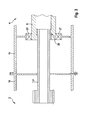
- In
Figur 2 ist ein an einem Getriebegehäuse 18 des Planetengetriebes 2 angeflanschtes Generatorgehäuse 19 des Generators 4 zu sehen. Eine doppelkardanisch gelagerte Getriebeabtriebswelle 7 dient als Kupplungsmittel zwischen der Generatorwelle 6, welche über Lager 21 am Generatorgehäuse 19 gelagert ist, und einem Sonnenrad 8 des Planetengetriebes 2. Die Getriebeabtriebswelle 7 weist somit an dem Sonnenrad 8 und an der Generatorwelle 6 jeweils ein Gelenk 20 auf, so dass getriebeseitig das Sonnenrad 8 als Anlenkpunkt dient und generatorseitig die Generatorwelle 6 als Anlenkpunkt dient. Hierrüber erfolgt die Kompensation von Axial-, Radial- und Winkelversatz zwischen Planetengetriebe 2 und Generator 4. - Nach
Figur 3 erfolgt die Kompensation von Axial-, Radial- und Winkelversatz zwischen Planetengetriebe 2 und Generator 4 über eine zwischen dem Planetengetriebe 2 und der Generatorwelle 6 angeordnete als Sonnenradwelle 9 ausgebildete generatorseitig kardanisch gelagerte Getriebeabtriebswelle 7. Die Getriebeabtriebswelle 7 weist somit nur ein Gelenk 20 auf, welches an der Innenumfangsfläche der Generatorwelle 6 angeordnet ist. Ferner weist die Getriebeabtriebswelle 7 eine entsprechende Länge auf, so dass der Radialversatz durch den Winkelversatz kompensiert wird und der Axialversatz durch die kardanische Lagerung kompensiert wird. - In
Figur 4 ist das Kupplungsmittel generatorseitig an die Getriebeabtriebswelle 7 angeordnet. Ferner ist die als Sonnenradwelle 9 ausgebildete Getriebeabtriebswelle 7 zwischen dem Planetengetriebe 2 und der Generatorwelle 6 angeordnet. Das zum Generator gerichtete Ende der Sonnenradwelle 9 ist zu einem Kupplungsflansch 13 ausgebildet. Als Kupplungsmittel ist eine Doppellamellenkupplung 10 an die Stirnfläche des Kupplungsflanschs 13 angeordnet. Ebenso wäre die Anordnung einer Zahnkupplung 11 und/oder einer Laschenkupplung 12 an derselben Position möglich. Radial zwischen einem Außenumfang der Sonnenradwelle 9 und dem Getriebegehäuse 18 ist ein Dichtungselement 22 angeordnet, welches den Generator 4 vom Getriebe 2 öldicht abdichtet. - Es sei darauf hingewiesen, dass Merkmale, die mit Verweis auf eines der obigen Ausführungsbeispiele beschrieben worden sind, auch in Kombination mit anderen Merkmalen oder Schritten anderer oben beschriebener Ausführungsbeispiele verwendet werden können. Bezugszeichen in den Ansprüchen sind nicht als Einschränkung anzusehen.
-
- 1
- Windkraftanlage
- 2
- Planetengetriebe
- 3
- Rotor
- 4
- Generator
- 5
- Getriebeantriebswelle
- 6
- Generatorwelle
- 7
- Getriebeabtriebswelle
- 8
- Sonnenrad
- 9
- Sonnenradwelle
- 10
- Doppellamellenkupplung
- 11
- Zahnkupplung
- 12
- Laschenkupplung
- 13
- Kupplungsflansch
- 14
- Turm
- 15
- Gondel
- 16
- Nabe
- 17
- Rotorblätter
- 18
- Getriebegehäuse
- 19
- Generatorgehäuse
- 20
- Gelenk
- 21
- Lager
- 22
- Dichtungselement
Claims (10)
- Windkraftanlage (1) mit einem Planetengetriebe (2), welches zur Umwandelung einer langsamen Drehbewegung eines Rotors (3) in eine schnelle Drehbewegung zum Betrieb eines integrierten mittellschnelllaufenden elektrischen Generators (4) angeordnet ist, umfassend eine mittelbar mit dem Rotor (3) verbundene Getriebeantriebswelle (5) und eine mittelbar über eine Generatorwelle (6) mit dem Generator (4) verbundene Getriebeabtriebswelle (7), wobei zwischen dem Generator (4) und dem Planetengetriebe (2) ein Kupplungsmittel angeordnet ist,
dadurch gekennzeichnet, dass das Kupplungsmittel zum Ausgleich von Axial-, Radial- und Winkelversatz zwischen Planetengetriebe (2) und Generatorwelle (6) angeordnet ist. - Windkraftanlage (1) nach Anspruch 1,
dadurch gekennzeichnet, dass das Kupplungsmittel eine zwischen einer Generatorwelle (6) und einem Sonnenrad (8) des Planetengetriebes (2) angeordnete doppelkardanisch gelagerte Getriebeabtriebswelle (5) ist. - Windkraftanlage (1) nach Anspruch 1,
dadurch gekennzeichnet, dass das Kupplungsmittel eine zwischen Planetengetriebe (2) und Generatorwelle (6) angeordnete als Sonnenradwelle (9) ausgebildete generatorseitig kardanisch gelagerte Getriebeabtriebswelle (7) ist. - Windkraftanlage (1) nach Anspruch 1,
dadurch gekennzeichnet, dass das Kupplungsmittel generatorseitig an eine zwischen Planetengetriebe (2) und Generatorwelle (6) angeordnete als Sonnenradwelle (9) ausgebildete Getriebeabtriebswelle (7) mit getriebeseitiger Laufverzahnung angeordnet ist. - Windkraftanlage (1) nach Anspruch 4,
dadurch gekennzeichnet, dass das generatorseitige Kupplungsmittel mindestens eine Doppellamellenkupplung (10), mindestens eine Zahnkupplung (11) und/oder mindestens eine Laschenkupplung (12) umfasst. - Windkraftanlage (1) nach Anspruch 4,
dadurch gekennzeichnet, dass das generatorseitige Kupplungsmittel an der Sonnenradwelle (9) angeflanscht ist, wobei zwischen dem angeflanschten Kupplungsmittel und der Sonnenradwelle (9) eine form- oder kraftschlüssige Verbindung vorgesehen ist. - Windkraftanlage (1) nach Anspruch 6,
dadurch gekennzeichnet, dass bei der reibschlüssigen Verbindung zwischen dem angeflanschten Kupplungsmittel und der Sonnenradwelle (9) axial an den Stirnflächen der Verbindungsstellen reibwerterhöhende Mittel vorgesehen sind. - Windkraftanlage (1) nach Anspruch 4,
dadurch gekennzeichnet, dass ein generatorseitiger Kupplungsflansch (13) direkt an der Sonnenradwelle (9) angeschmiedet ist. - Windkraftanlage (1) nach einem der vorhergehenden Ansprüche,
dadurch gekennzeichnet, dass ein schmierungsbedürftiges Kupplungsmittel mit Getriebeöl zur Schmierung und Kühlung versorgbar ist, wobei das schmierungsbedürftige Kupplungsmittel gegenüber dem Generator (4) durch ein Dichtungselement (22) öldicht abgedichtet ist. - Windkraftanlage (1) nach einem der vorhergehenden Ansprüche,
dadurch gekennzeichnet, dass das Kupplungsmittel stromisolierend ist oder zumindest stromisolierende Mittel aufweist.
Applications Claiming Priority (1)
| Application Number | Priority Date | Filing Date | Title |
|---|---|---|---|
| DE102012012106A DE102012012106A1 (de) | 2012-06-18 | 2012-06-18 | Windkraftanlage mit einem zwischen Planetengetriebeund Generator angeordneten Kupplungsmittel zumAusgleich von Axial-, Radial- und Winkelversatz |
Publications (3)
| Publication Number | Publication Date |
|---|---|
| EP2677171A2 true EP2677171A2 (de) | 2013-12-25 |
| EP2677171A3 EP2677171A3 (de) | 2015-01-07 |
| EP2677171B1 EP2677171B1 (de) | 2018-07-18 |
Family
ID=48569927
Family Applications (1)
| Application Number | Title | Priority Date | Filing Date |
|---|---|---|---|
| EP13002852.5A Active EP2677171B1 (de) | 2012-06-18 | 2013-06-03 | Windkraftanlage mit einem zwischen Planetengetriebe und Generator angeordneten Kupplunsmittel zum Ausgleich von Axial, Radial- uns Winkelversatz |
Country Status (6)
| Country | Link |
|---|---|
| US (1) | US9206882B2 (de) |
| EP (1) | EP2677171B1 (de) |
| CN (1) | CN103511197B (de) |
| DE (1) | DE102012012106A1 (de) |
| DK (1) | DK2677171T3 (de) |
| ES (1) | ES2689800T3 (de) |
Families Citing this family (4)
| Publication number | Priority date | Publication date | Assignee | Title |
|---|---|---|---|---|
| ES2864648T3 (es) * | 2016-10-05 | 2021-10-14 | Flender Gmbh | Cojinete para una rueda planetaria de un engranaje planetario |
| DE102018205868A1 (de) * | 2018-04-18 | 2019-10-24 | Zf Friedrichshafen Ag | Getriebestufen mit Winkelversatz |
| EP3798467A1 (de) | 2019-09-30 | 2021-03-31 | Adwen GmbH | Antriebsstrang einer windturbine mit einer kupplungswelle zum ausgleich von rundlauftoleranzen und fehlausrichtung einer getriebeausgangsachse und einer generatordrehachse |
| EP4644691A1 (de) * | 2024-04-30 | 2025-11-05 | Flender GmbH | Antriebsstrang für eine windkraftanlage |
Citations (1)
| Publication number | Priority date | Publication date | Assignee | Title |
|---|---|---|---|---|
| US8075442B2 (en) | 2008-09-05 | 2011-12-13 | General Electric Company | System and assembly for power transmission and generation in a wind turbine |
Family Cites Families (12)
| Publication number | Priority date | Publication date | Assignee | Title |
|---|---|---|---|---|
| CN1109562A (zh) * | 1994-04-01 | 1995-10-04 | 张远明 | 十字轴联轴器 |
| FI108959B (fi) * | 1998-06-18 | 2002-04-30 | Valmet Voimansiirto Oy | Tuulivoimalan planeettavaihteisto |
| US8167727B2 (en) * | 2009-10-02 | 2012-05-01 | Opra Technologies | High speed gear coupler |
| FI117252B (fi) * | 2004-07-15 | 2006-08-15 | Moventas Oy | Sovitelma planeettavaihteistossa |
| DE102006051546A1 (de) | 2006-11-02 | 2008-05-08 | Nordex Energy Gmbh | Verfahren zum Betrieb einer Windenergieanlage mit einem doppelt gespeisten Asynchrongenerator sowie Windenergieanlage mit einem doppelt gespeisten Asynchrongenerator |
| EP2075466B8 (de) * | 2007-12-28 | 2012-04-04 | Gamesa Innovation & Technology, S.L. | Verfahren zum Anschließen einer langsamen Windturbinenhauptwelle an eine Eingangswelle eines Windturbinengetriebes und durch dieses Verfahren erhaltene Kopplungsvorrichtung |
| US8517844B2 (en) * | 2008-11-26 | 2013-08-27 | Sgf Sueddeutsche Gelenkscheibenfabrik Gmbh & Co. Kg | Torque transmitting device |
| DE102009052240A1 (de) * | 2009-11-06 | 2011-05-12 | Fev Motorentechnik Gmbh | Windkraftanlage |
| AU2010201623B2 (en) * | 2010-02-12 | 2011-09-08 | Mitsubishi Heavy Industries, Ltd. | Gear box for wind turbine generator and wind turbine generator |
| DE202010012752U1 (de) * | 2010-09-20 | 2010-12-02 | Centa-Antriebe Kirschey Gmbh | Vorrichtung zur kraftübertragenden Verbindung zweier Aggregate |
| DK2630371T4 (da) * | 2010-10-18 | 2021-12-20 | Vestas Wind Sys As | Vindmølleeffekttransmissionssystem |
| US9041237B2 (en) * | 2012-02-24 | 2015-05-26 | General Electric Company | Wind turbine drive train and wind turbine |
-
2012
- 2012-06-18 DE DE102012012106A patent/DE102012012106A1/de not_active Withdrawn
-
2013
- 2013-06-03 DK DK13002852.5T patent/DK2677171T3/en active
- 2013-06-03 EP EP13002852.5A patent/EP2677171B1/de active Active
- 2013-06-03 ES ES13002852.5T patent/ES2689800T3/es active Active
- 2013-06-13 US US13/916,688 patent/US9206882B2/en active Active
- 2013-06-17 CN CN201310237994.4A patent/CN103511197B/zh active Active
Patent Citations (1)
| Publication number | Priority date | Publication date | Assignee | Title |
|---|---|---|---|---|
| US8075442B2 (en) | 2008-09-05 | 2011-12-13 | General Electric Company | System and assembly for power transmission and generation in a wind turbine |
Also Published As
| Publication number | Publication date |
|---|---|
| US20130337969A1 (en) | 2013-12-19 |
| DK2677171T3 (en) | 2018-11-05 |
| CN103511197B (zh) | 2018-09-11 |
| US9206882B2 (en) | 2015-12-08 |
| EP2677171A3 (de) | 2015-01-07 |
| ES2689800T3 (es) | 2018-11-15 |
| EP2677171B1 (de) | 2018-07-18 |
| DE102012012106A1 (de) | 2013-12-19 |
| CN103511197A (zh) | 2014-01-15 |
Similar Documents
| Publication | Publication Date | Title |
|---|---|---|
| EP2097641B1 (de) | Leistungsverzweigtes windkraftgetriebe | |
| EP2116722B1 (de) | Positionierung eines Rotors einer Windenergieanlage | |
| EP1999369B1 (de) | Antriebsstrang zwischen einem rotor und einem getriebe einer windenergieanlage | |
| EP2499362A2 (de) | Antriebseinheit für windturbine | |
| EP1867871A2 (de) | Windenergieanlage mit einem Rotor | |
| WO2015158753A1 (de) | Antriebssystem einer windkraftanlage | |
| EP1955976A1 (de) | Windenvorrichtung | |
| EP2677171B1 (de) | Windkraftanlage mit einem zwischen Planetengetriebe und Generator angeordneten Kupplunsmittel zum Ausgleich von Axial, Radial- uns Winkelversatz | |
| DE102011011164A1 (de) | Rotorlagerung für elektrische Maschine | |
| DE10334448A1 (de) | Windkraftanlage | |
| WO2009100720A2 (de) | Vorrichtung zur drehmomentbegrenzung in einem triebstrang | |
| EP3767102B1 (de) | Triebstranganordnung | |
| DE102017111041B3 (de) | Antriebsvorrichtung für ein Kraftfahrzeug | |
| DE102015226679A1 (de) | Getriebe für ein Kraftfahrzeug | |
| EP2761174B1 (de) | Getriebe einer windenergieanlage mit hilfsantrieb, windenergieanlage und verfahren zum drehen einer rotorwelle einer windenergieanlage | |
| DE102016225972B4 (de) | Getriebe für ein Kraftfahrzeug | |
| EP1936233A2 (de) | Getriebeeinheit mit integrierter Ausgleichskupplung | |
| DE102011118137A1 (de) | Welle | |
| WO2023165769A1 (de) | Planetengetriebeanordnung mit im/am planetenträger gelagerter sonnenwelle, entsprechendes industriegetriebe sowie verwendung | |
| EP2870356A1 (de) | Antriebsstrang für eine windkraftanlage | |
| EP1551661A1 (de) | Wellenstrang, insbesondere gelenkwelle und homokinetischer drehgestellantrieb für schienenfahrzeuge | |
| EP4043756A1 (de) | Planetenträgeranordnung, planetengetriebe, antriebsstrang, windkraftanlage und computerprogrammprodukt | |
| EP4653716A1 (de) | Welle-nabe-verbindung mit axialsicherung | |
| EP4530500A1 (de) | Welle-nabe-verbindung mit verschleissoptimierter schicht | |
| DE102017123620A1 (de) | Verfahren zum Verbinden eines Elektromotors und eines Getriebes, insbesondere bei einem Elektrofahrzeug |
Legal Events
| Date | Code | Title | Description |
|---|---|---|---|
| PUAI | Public reference made under article 153(3) epc to a published international application that has entered the european phase |
Free format text: ORIGINAL CODE: 0009012 |
|
| AK | Designated contracting states |
Kind code of ref document: A2 Designated state(s): AL AT BE BG CH CY CZ DE DK EE ES FI FR GB GR HR HU IE IS IT LI LT LU LV MC MK MT NL NO PL PT RO RS SE SI SK SM TR |
|
| AX | Request for extension of the european patent |
Extension state: BA ME |
|
| PUAL | Search report despatched |
Free format text: ORIGINAL CODE: 0009013 |
|
| AK | Designated contracting states |
Kind code of ref document: A3 Designated state(s): AL AT BE BG CH CY CZ DE DK EE ES FI FR GB GR HR HU IE IS IT LI LT LU LV MC MK MT NL NO PL PT RO RS SE SI SK SM TR |
|
| AX | Request for extension of the european patent |
Extension state: BA ME |
|
| RIC1 | Information provided on ipc code assigned before grant |
Ipc: F03D 11/02 20060101AFI20141128BHEP |
|
| 17P | Request for examination filed |
Effective date: 20150707 |
|
| RBV | Designated contracting states (corrected) |
Designated state(s): AL AT BE BG CH CY CZ DE DK EE ES FI FR GB GR HR HU IE IS IT LI LT LU LV MC MK MT NL NO PL PT RO RS SE SI SK SM TR |
|
| RAP1 | Party data changed (applicant data changed or rights of an application transferred) |
Owner name: ZF FRIEDRICHSHAFEN AG |
|
| STAA | Information on the status of an ep patent application or granted ep patent |
Free format text: STATUS: EXAMINATION IS IN PROGRESS |
|
| 17Q | First examination report despatched |
Effective date: 20171212 |
|
| REG | Reference to a national code |
Ref country code: DE Ref legal event code: R079 Ref document number: 502013010618 Country of ref document: DE Free format text: PREVIOUS MAIN CLASS: F03D0011020000 Ipc: F03D0015000000 |
|
| GRAP | Despatch of communication of intention to grant a patent |
Free format text: ORIGINAL CODE: EPIDOSNIGR1 |
|
| STAA | Information on the status of an ep patent application or granted ep patent |
Free format text: STATUS: GRANT OF PATENT IS INTENDED |
|
| RIC1 | Information provided on ipc code assigned before grant |
Ipc: F03D 15/00 20160101AFI20180125BHEP |
|
| INTG | Intention to grant announced |
Effective date: 20180215 |
|
| GRAS | Grant fee paid |
Free format text: ORIGINAL CODE: EPIDOSNIGR3 |
|
| GRAA | (expected) grant |
Free format text: ORIGINAL CODE: 0009210 |
|
| STAA | Information on the status of an ep patent application or granted ep patent |
Free format text: STATUS: THE PATENT HAS BEEN GRANTED |
|
| AK | Designated contracting states |
Kind code of ref document: B1 Designated state(s): AL AT BE BG CH CY CZ DE DK EE ES FI FR GB GR HR HU IE IS IT LI LT LU LV MC MK MT NL NO PL PT RO RS SE SI SK SM TR |
|
| REG | Reference to a national code |
Ref country code: GB Ref legal event code: FG4D Free format text: NOT ENGLISH |
|
| REG | Reference to a national code |
Ref country code: CH Ref legal event code: EP |
|
| REG | Reference to a national code |
Ref country code: IE Ref legal event code: FG4D Free format text: LANGUAGE OF EP DOCUMENT: GERMAN |
|
| REG | Reference to a national code |
Ref country code: AT Ref legal event code: REF Ref document number: 1019650 Country of ref document: AT Kind code of ref document: T Effective date: 20180815 |
|
| REG | Reference to a national code |
Ref country code: DE Ref legal event code: R096 Ref document number: 502013010618 Country of ref document: DE |
|
| REG | Reference to a national code |
Ref country code: DK Ref legal event code: T3 Effective date: 20181022 |
|
| REG | Reference to a national code |
Ref country code: ES Ref legal event code: FG2A Ref document number: 2689800 Country of ref document: ES Kind code of ref document: T3 Effective date: 20181115 |
|
| REG | Reference to a national code |
Ref country code: NL Ref legal event code: MP Effective date: 20180718 |
|
| REG | Reference to a national code |
Ref country code: LT Ref legal event code: MG4D |
|
| PG25 | Lapsed in a contracting state [announced via postgrant information from national office to epo] |
Ref country code: NL Free format text: LAPSE BECAUSE OF FAILURE TO SUBMIT A TRANSLATION OF THE DESCRIPTION OR TO PAY THE FEE WITHIN THE PRESCRIBED TIME-LIMIT Effective date: 20180718 |
|
| PG25 | Lapsed in a contracting state [announced via postgrant information from national office to epo] |
Ref country code: LT Free format text: LAPSE BECAUSE OF FAILURE TO SUBMIT A TRANSLATION OF THE DESCRIPTION OR TO PAY THE FEE WITHIN THE PRESCRIBED TIME-LIMIT Effective date: 20180718 Ref country code: PL Free format text: LAPSE BECAUSE OF FAILURE TO SUBMIT A TRANSLATION OF THE DESCRIPTION OR TO PAY THE FEE WITHIN THE PRESCRIBED TIME-LIMIT Effective date: 20180718 Ref country code: RS Free format text: LAPSE BECAUSE OF FAILURE TO SUBMIT A TRANSLATION OF THE DESCRIPTION OR TO PAY THE FEE WITHIN THE PRESCRIBED TIME-LIMIT Effective date: 20180718 Ref country code: IS Free format text: LAPSE BECAUSE OF FAILURE TO SUBMIT A TRANSLATION OF THE DESCRIPTION OR TO PAY THE FEE WITHIN THE PRESCRIBED TIME-LIMIT Effective date: 20181118 Ref country code: BG Free format text: LAPSE BECAUSE OF FAILURE TO SUBMIT A TRANSLATION OF THE DESCRIPTION OR TO PAY THE FEE WITHIN THE PRESCRIBED TIME-LIMIT Effective date: 20181018 Ref country code: GR Free format text: LAPSE BECAUSE OF FAILURE TO SUBMIT A TRANSLATION OF THE DESCRIPTION OR TO PAY THE FEE WITHIN THE PRESCRIBED TIME-LIMIT Effective date: 20181019 Ref country code: NO Free format text: LAPSE BECAUSE OF FAILURE TO SUBMIT A TRANSLATION OF THE DESCRIPTION OR TO PAY THE FEE WITHIN THE PRESCRIBED TIME-LIMIT Effective date: 20181018 Ref country code: SE Free format text: LAPSE BECAUSE OF FAILURE TO SUBMIT A TRANSLATION OF THE DESCRIPTION OR TO PAY THE FEE WITHIN THE PRESCRIBED TIME-LIMIT Effective date: 20180718 |
|
| REG | Reference to a national code |
Ref country code: CH Ref legal event code: PK Free format text: BERICHTIGUNGEN |
|
| RIC2 | Information provided on ipc code assigned after grant |
Ipc: F03D 15/00 20160101AFI20180125BHEP |
|
| PG25 | Lapsed in a contracting state [announced via postgrant information from national office to epo] |
Ref country code: HR Free format text: LAPSE BECAUSE OF FAILURE TO SUBMIT A TRANSLATION OF THE DESCRIPTION OR TO PAY THE FEE WITHIN THE PRESCRIBED TIME-LIMIT Effective date: 20180718 Ref country code: AL Free format text: LAPSE BECAUSE OF FAILURE TO SUBMIT A TRANSLATION OF THE DESCRIPTION OR TO PAY THE FEE WITHIN THE PRESCRIBED TIME-LIMIT Effective date: 20180718 Ref country code: LV Free format text: LAPSE BECAUSE OF FAILURE TO SUBMIT A TRANSLATION OF THE DESCRIPTION OR TO PAY THE FEE WITHIN THE PRESCRIBED TIME-LIMIT Effective date: 20180718 |
|
| REG | Reference to a national code |
Ref country code: DE Ref legal event code: R097 Ref document number: 502013010618 Country of ref document: DE |
|
| PG25 | Lapsed in a contracting state [announced via postgrant information from national office to epo] |
Ref country code: CZ Free format text: LAPSE BECAUSE OF FAILURE TO SUBMIT A TRANSLATION OF THE DESCRIPTION OR TO PAY THE FEE WITHIN THE PRESCRIBED TIME-LIMIT Effective date: 20180718 Ref country code: IT Free format text: LAPSE BECAUSE OF FAILURE TO SUBMIT A TRANSLATION OF THE DESCRIPTION OR TO PAY THE FEE WITHIN THE PRESCRIBED TIME-LIMIT Effective date: 20180718 Ref country code: RO Free format text: LAPSE BECAUSE OF FAILURE TO SUBMIT A TRANSLATION OF THE DESCRIPTION OR TO PAY THE FEE WITHIN THE PRESCRIBED TIME-LIMIT Effective date: 20180718 Ref country code: EE Free format text: LAPSE BECAUSE OF FAILURE TO SUBMIT A TRANSLATION OF THE DESCRIPTION OR TO PAY THE FEE WITHIN THE PRESCRIBED TIME-LIMIT Effective date: 20180718 |
|
| PLBE | No opposition filed within time limit |
Free format text: ORIGINAL CODE: 0009261 |
|
| STAA | Information on the status of an ep patent application or granted ep patent |
Free format text: STATUS: NO OPPOSITION FILED WITHIN TIME LIMIT |
|
| PG25 | Lapsed in a contracting state [announced via postgrant information from national office to epo] |
Ref country code: SM Free format text: LAPSE BECAUSE OF FAILURE TO SUBMIT A TRANSLATION OF THE DESCRIPTION OR TO PAY THE FEE WITHIN THE PRESCRIBED TIME-LIMIT Effective date: 20180718 Ref country code: SK Free format text: LAPSE BECAUSE OF FAILURE TO SUBMIT A TRANSLATION OF THE DESCRIPTION OR TO PAY THE FEE WITHIN THE PRESCRIBED TIME-LIMIT Effective date: 20180718 |
|
| 26N | No opposition filed |
Effective date: 20190423 |
|
| PGFP | Annual fee paid to national office [announced via postgrant information from national office to epo] |
Ref country code: DK Payment date: 20190613 Year of fee payment: 7 |
|
| PG25 | Lapsed in a contracting state [announced via postgrant information from national office to epo] |
Ref country code: SI Free format text: LAPSE BECAUSE OF FAILURE TO SUBMIT A TRANSLATION OF THE DESCRIPTION OR TO PAY THE FEE WITHIN THE PRESCRIBED TIME-LIMIT Effective date: 20180718 |
|
| PG25 | Lapsed in a contracting state [announced via postgrant information from national office to epo] |
Ref country code: MC Free format text: LAPSE BECAUSE OF FAILURE TO SUBMIT A TRANSLATION OF THE DESCRIPTION OR TO PAY THE FEE WITHIN THE PRESCRIBED TIME-LIMIT Effective date: 20180718 |
|
| REG | Reference to a national code |
Ref country code: CH Ref legal event code: PL |
|
| GBPC | Gb: european patent ceased through non-payment of renewal fee |
Effective date: 20190603 |
|
| REG | Reference to a national code |
Ref country code: BE Ref legal event code: MM Effective date: 20190630 |
|
| PG25 | Lapsed in a contracting state [announced via postgrant information from national office to epo] |
Ref country code: TR Free format text: LAPSE BECAUSE OF FAILURE TO SUBMIT A TRANSLATION OF THE DESCRIPTION OR TO PAY THE FEE WITHIN THE PRESCRIBED TIME-LIMIT Effective date: 20180718 |
|
| PG25 | Lapsed in a contracting state [announced via postgrant information from national office to epo] |
Ref country code: IE Free format text: LAPSE BECAUSE OF NON-PAYMENT OF DUE FEES Effective date: 20190603 Ref country code: GB Free format text: LAPSE BECAUSE OF NON-PAYMENT OF DUE FEES Effective date: 20190603 |
|
| PG25 | Lapsed in a contracting state [announced via postgrant information from national office to epo] |
Ref country code: LI Free format text: LAPSE BECAUSE OF NON-PAYMENT OF DUE FEES Effective date: 20190630 Ref country code: CH Free format text: LAPSE BECAUSE OF NON-PAYMENT OF DUE FEES Effective date: 20190630 Ref country code: LU Free format text: LAPSE BECAUSE OF NON-PAYMENT OF DUE FEES Effective date: 20190603 Ref country code: BE Free format text: LAPSE BECAUSE OF NON-PAYMENT OF DUE FEES Effective date: 20190630 |
|
| PG25 | Lapsed in a contracting state [announced via postgrant information from national office to epo] |
Ref country code: FR Free format text: LAPSE BECAUSE OF NON-PAYMENT OF DUE FEES Effective date: 20190630 Ref country code: PT Free format text: LAPSE BECAUSE OF FAILURE TO SUBMIT A TRANSLATION OF THE DESCRIPTION OR TO PAY THE FEE WITHIN THE PRESCRIBED TIME-LIMIT Effective date: 20181118 |
|
| REG | Reference to a national code |
Ref country code: AT Ref legal event code: MM01 Ref document number: 1019650 Country of ref document: AT Kind code of ref document: T Effective date: 20190603 |
|
| PG25 | Lapsed in a contracting state [announced via postgrant information from national office to epo] |
Ref country code: AT Free format text: LAPSE BECAUSE OF NON-PAYMENT OF DUE FEES Effective date: 20190603 |
|
| REG | Reference to a national code |
Ref country code: DK Ref legal event code: EBP Effective date: 20200630 |
|
| PG25 | Lapsed in a contracting state [announced via postgrant information from national office to epo] |
Ref country code: CY Free format text: LAPSE BECAUSE OF FAILURE TO SUBMIT A TRANSLATION OF THE DESCRIPTION OR TO PAY THE FEE WITHIN THE PRESCRIBED TIME-LIMIT Effective date: 20180718 |
|
| PG25 | Lapsed in a contracting state [announced via postgrant information from national office to epo] |
Ref country code: HU Free format text: LAPSE BECAUSE OF FAILURE TO SUBMIT A TRANSLATION OF THE DESCRIPTION OR TO PAY THE FEE WITHIN THE PRESCRIBED TIME-LIMIT; INVALID AB INITIO Effective date: 20130603 Ref country code: MT Free format text: LAPSE BECAUSE OF FAILURE TO SUBMIT A TRANSLATION OF THE DESCRIPTION OR TO PAY THE FEE WITHIN THE PRESCRIBED TIME-LIMIT Effective date: 20180718 |
|
| PG25 | Lapsed in a contracting state [announced via postgrant information from national office to epo] |
Ref country code: DK Free format text: LAPSE BECAUSE OF NON-PAYMENT OF DUE FEES Effective date: 20200630 |
|
| PG25 | Lapsed in a contracting state [announced via postgrant information from national office to epo] |
Ref country code: MK Free format text: LAPSE BECAUSE OF FAILURE TO SUBMIT A TRANSLATION OF THE DESCRIPTION OR TO PAY THE FEE WITHIN THE PRESCRIBED TIME-LIMIT Effective date: 20180718 |
|
| P01 | Opt-out of the competence of the unified patent court (upc) registered |
Effective date: 20230528 |
|
| PGFP | Annual fee paid to national office [announced via postgrant information from national office to epo] |
Ref country code: FI Payment date: 20250620 Year of fee payment: 13 |
|
| PGFP | Annual fee paid to national office [announced via postgrant information from national office to epo] |
Ref country code: DE Payment date: 20250402 Year of fee payment: 13 |
|
| PGFP | Annual fee paid to national office [announced via postgrant information from national office to epo] |
Ref country code: ES Payment date: 20250703 Year of fee payment: 13 |