EP2677187B1 - Reibring, Synchronisierungseinheit, sowie ein Zahnräderwechselgetriebe für ein Fahrzeug - Google Patents
Reibring, Synchronisierungseinheit, sowie ein Zahnräderwechselgetriebe für ein Fahrzeug Download PDFInfo
- Publication number
- EP2677187B1 EP2677187B1 EP13169504.1A EP13169504A EP2677187B1 EP 2677187 B1 EP2677187 B1 EP 2677187B1 EP 13169504 A EP13169504 A EP 13169504A EP 2677187 B1 EP2677187 B1 EP 2677187B1
- Authority
- EP
- European Patent Office
- Prior art keywords
- friction
- friction ring
- angle
- ring
- anyone
- Prior art date
- Legal status (The legal status is an assumption and is not a legal conclusion. Google has not performed a legal analysis and makes no representation as to the accuracy of the status listed.)
- Active
Links
- 238000009434 installation Methods 0.000 claims description 26
- 230000005540 biological transmission Effects 0.000 claims description 17
- 230000008859 change Effects 0.000 claims description 9
- 229910000831 Steel Inorganic materials 0.000 claims description 5
- 239000011248 coating agent Substances 0.000 claims description 5
- 238000000576 coating method Methods 0.000 claims description 5
- 239000010959 steel Substances 0.000 claims description 5
- 229910052799 carbon Inorganic materials 0.000 claims description 3
- 229910052751 metal Inorganic materials 0.000 claims description 3
- 239000002184 metal Substances 0.000 claims description 3
- 150000001721 carbon Chemical class 0.000 claims description 2
- 230000000694 effects Effects 0.000 description 7
- 238000004519 manufacturing process Methods 0.000 description 4
- 230000001360 synchronised effect Effects 0.000 description 4
- 239000000463 material Substances 0.000 description 3
- 238000000034 method Methods 0.000 description 3
- 230000008569 process Effects 0.000 description 3
- 230000003014 reinforcing effect Effects 0.000 description 3
- 238000006243 chemical reaction Methods 0.000 description 2
- 239000002783 friction material Substances 0.000 description 2
- 238000005457 optimization Methods 0.000 description 2
- 238000000926 separation method Methods 0.000 description 2
- 229910001369 Brass Inorganic materials 0.000 description 1
- OKTJSMMVPCPJKN-UHFFFAOYSA-N Carbon Chemical compound [C] OKTJSMMVPCPJKN-UHFFFAOYSA-N 0.000 description 1
- ZOKXTWBITQBERF-UHFFFAOYSA-N Molybdenum Chemical compound [Mo] ZOKXTWBITQBERF-UHFFFAOYSA-N 0.000 description 1
- 230000000903 blocking effect Effects 0.000 description 1
- 239000010951 brass Substances 0.000 description 1
- 238000010276 construction Methods 0.000 description 1
- 230000008878 coupling Effects 0.000 description 1
- 238000010168 coupling process Methods 0.000 description 1
- 238000005859 coupling reaction Methods 0.000 description 1
- 230000001419 dependent effect Effects 0.000 description 1
- 238000011161 development Methods 0.000 description 1
- 230000018109 developmental process Effects 0.000 description 1
- 230000009977 dual effect Effects 0.000 description 1
- 230000008030 elimination Effects 0.000 description 1
- 238000003379 elimination reaction Methods 0.000 description 1
- 238000005516 engineering process Methods 0.000 description 1
- 230000007246 mechanism Effects 0.000 description 1
- 229910001092 metal group alloy Inorganic materials 0.000 description 1
- 229910052750 molybdenum Inorganic materials 0.000 description 1
- 239000011733 molybdenum Substances 0.000 description 1
- 230000002093 peripheral effect Effects 0.000 description 1
- 230000002028 premature Effects 0.000 description 1
- 238000001228 spectrum Methods 0.000 description 1
- 239000007921 spray Substances 0.000 description 1
- 230000003068 static effect Effects 0.000 description 1
Images



Classifications
-
- F—MECHANICAL ENGINEERING; LIGHTING; HEATING; WEAPONS; BLASTING
- F16—ENGINEERING ELEMENTS AND UNITS; GENERAL MEASURES FOR PRODUCING AND MAINTAINING EFFECTIVE FUNCTIONING OF MACHINES OR INSTALLATIONS; THERMAL INSULATION IN GENERAL
- F16D—COUPLINGS FOR TRANSMITTING ROTATION; CLUTCHES; BRAKES
- F16D23/00—Details of mechanically-actuated clutches not specific for one distinct type
- F16D23/02—Arrangements for synchronisation, also for power-operated clutches
- F16D23/025—Synchro rings
-
- F—MECHANICAL ENGINEERING; LIGHTING; HEATING; WEAPONS; BLASTING
- F16—ENGINEERING ELEMENTS AND UNITS; GENERAL MEASURES FOR PRODUCING AND MAINTAINING EFFECTIVE FUNCTIONING OF MACHINES OR INSTALLATIONS; THERMAL INSULATION IN GENERAL
- F16D—COUPLINGS FOR TRANSMITTING ROTATION; CLUTCHES; BRAKES
- F16D23/00—Details of mechanically-actuated clutches not specific for one distinct type
- F16D23/02—Arrangements for synchronisation, also for power-operated clutches
- F16D23/04—Arrangements for synchronisation, also for power-operated clutches with an additional friction clutch
- F16D23/06—Arrangements for synchronisation, also for power-operated clutches with an additional friction clutch and a blocking mechanism preventing the engagement of the main clutch prior to synchronisation
-
- F—MECHANICAL ENGINEERING; LIGHTING; HEATING; WEAPONS; BLASTING
- F16—ENGINEERING ELEMENTS AND UNITS; GENERAL MEASURES FOR PRODUCING AND MAINTAINING EFFECTIVE FUNCTIONING OF MACHINES OR INSTALLATIONS; THERMAL INSULATION IN GENERAL
- F16D—COUPLINGS FOR TRANSMITTING ROTATION; CLUTCHES; BRAKES
- F16D23/00—Details of mechanically-actuated clutches not specific for one distinct type
- F16D23/02—Arrangements for synchronisation, also for power-operated clutches
- F16D23/04—Arrangements for synchronisation, also for power-operated clutches with an additional friction clutch
- F16D23/06—Arrangements for synchronisation, also for power-operated clutches with an additional friction clutch and a blocking mechanism preventing the engagement of the main clutch prior to synchronisation
- F16D2023/0681—Double cone synchromesh clutches
Definitions
- the invention relates to a friction ring for a synchronization unit of a switchable gear change transmission, a synchronization unit, and a gear change transmission for a vehicle according to the preamble of the independent claims.
- Synchronizer rings are used in a mechanical switchable gear change transmission, e.g. in vehicle transmissions to match the relative speeds between the gear wheel and the gear shaft that occur during a gear change.
- the synchronization is achieved through friction between the corresponding friction partners.
- the mode of operation of such gears and the sequence of the synchronization process are known per se and need no longer be explained to the person skilled in the art here.
- synchronizer rings which in usually made of a metal or a metal alloy, such as brass or steel, to be provided with a friction layer.
- friction layers are used, for example thermal spray layers made of molybdenum, carbon friction layers or friction layers made of other materials.
- Synchronization units for gear change transmissions or individual components of synchronization units are described in the prior art in a diverse and detailed manner.
- the cone angle is one of the most important factors when determining the friction torque in combination with the diameter of the cone and the coefficient of friction between the gear and the cone surface of the synchronizer ring. Reducing the cone angle increases the torque. This reduces the switching force and shorter synchronization times can be achieved.
- the cone angle has a major influence in determining the quality of the driver's shaft feel. An angle that is too small can produce unfavorable effects, e.g. B. block or second pressure points.
- a small cone angle is required to achieve maximum switching performance.
- a large cone angle is required. This results in a conflict of goals with regard to the design for conventional synchronizations.
- each synchronization is limited by design and application to an achievable performance, be it the diameter, coefficient of friction, or the minimum cone angle.
- the level at second pressure points also increases due to self-locking. This makes the circuit uncomfortable. In extreme cases, it can even lead to complete blocking.
- the friction ring has an outer and an inner friction surface for frictional contact with an outer and an inner synchronizing ring of the synchronizing device.
- the friction ring is designed in such a way that the frictional loads on the outer and inner friction surfaces are approximately the same. For this purpose, an interruption is provided on the circumference of the friction ring and the two friction surfaces have different cone angles.
- the object of the invention is therefore to provide an improved synchronization mechanism and the components necessary for this, so that the disadvantages described at the outset and known from the prior art can be avoided.
- the present invention is intended to resolve the conflict of objectives with regard to efficiency and shifting comfort.
- the invention is intended on the one hand to achieve a high efficiency of the friction pairing, that is to say to achieve a reinforcing effect, so that the cone can generate high synchronization moments despite low actuation forces.
- the self-locking effect which prevents or at least complicates loosening of the friction surfaces and at the same time significantly and noticeably affects the shifting comfort for the driver, should be avoided as far as possible or to an appropriate extent be reduced.
- the object of the invention is thus an optimization of the synchronization without having to accept the compromises between efficiency and switching comfort necessary from the prior art.
- the invention thus relates to a friction ring for a synchronization unit of a gear change transmission, which friction ring comprises a conical friction ring body with an inner friction surface and an outer installation surface, preferably designed as a further friction surface, which respectively limit the friction ring body in a radial circumferential direction running perpendicular to an axial friction ring axis, and the inner friction surface extends conically along the friction ring axis at a predeterminable friction angle and the outer installation surface at a predeterminable installation angle.
- the friction angle is different from the installation angle.
- the friction ring is designed in such a way that the friction angle is different from the installation angle.
- the conflict of objectives regarding efficiency and shifting comfort that has existed in the prior art for a long time is reliably resolved.
- the invention achieves a high efficiency of the friction pairing, that is, a reinforcing effect is achieved, so that the cone can generate high synchronization moments despite low actuation forces.
- the known harmful self-locking effect which prevents loosening of the friction surfaces or at least makes it more difficult and substantially and noticeably affects the shifting comfort for the driver, is practically completely avoided by the invention.
- the invention makes it possible for the first time that the compromises between efficiency and switching comfort necessary from the prior art no longer have to be accepted.
- the novel approach according to the invention to resolve this conflict of objectives is the spatial separation of the functions "generate synchronization torque" and "release friction pairing", which were previously combined in one and the same friction pairing.
- the separation is made by a, preferably but not necessarily segmented, friction ring with different cone angles on the inside and Outside diameter reached.
- One diameter generates the synchronization torque in a force-fitting manner, the other diameter ensures that the force-fitting connection is released reliably.
- the two functions are independently optimized with regard to their specific requirements.
- the invention thus found for the first time that it is possible to resolve the known conflict of objectives by spatially separating the functions of the synchronization power (generation of low switching forces and short switching times) from the switching quality (second pressure point and self-locking effects). Both functions are directly connected to one another via the cone angle in the classic design known from the prior art, which had led to the described, previously unavoidable optimization problems.
- the invention also fulfills other essential requirements, which are essential in certain cases in order to achieve the desired result.
- the design according to the invention with an installation angle that differs from the friction angle takes up the entire spectrum of torque capacities and shifting comfort requirements of today's conventional synchronizations.
- the components of the synchronization unit according to the invention fit into the available installation space.
- the production of components according to the invention is also possible from stamped steel parts, which are therefore very simple and inexpensive to produce.
- the components of the present invention, in particular the friction ring are suitable for use and coating with existing technologies and processes, as well as the available friction materials, while at the same time the production and unit costs are at least equal or in practice often lower than those known today Multiple synchronizations fail.
- the innovative approach of the present invention namely to spatially separate the two functions of synchronization and solving, is described in Essentially by a small angle to the conical friction surface, which improves the performance or the torque capacities, and by a large angle to the release of the system, which achieves the negative effects of self-locking, which lead to poor shift quality.
- a further critical factor is taken into account, namely the forces in the circumferential direction (F U ) within the friction ring. Due to the small angle it is possible, depending on the application and embodiment, that self-locking can occur on the gear cone. To avoid this risk, the friction ring can also be segmented.
- the synchronizing ring is loaded with an external force F during synchronization. This creates external radial forces that act on the F rad segment.
- the reaction forces F ax and F rad on the friction surface are in equilibrium and are the same as in a conventional synchronization.
- the external force is then released.
- the large angle separates by ⁇ 2 > tan-1 ⁇ 2 and therefore there are no F rad that act on the segments and since there is no material stress within the segments by the friction element is not a fixed ring, the small angle separates because none internal or external forces act on them.
- the invention further relates to a manual transmission for a vehicle, in particular for a passenger car, a transporter or a truck with a synchronizer ring according to one of the preceding claims.
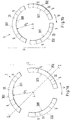
- Fig. 1a and Fig. 1b or the Fig. 1c and 1d show in a schematic representation one and the same very simple embodiment of a friction ring according to the invention with a segmented friction ring body, the friction ring being referred to in its entirety in the following with reference number 1.
- Fig. 1a shows the friction ring 1 in an expanded configuration
- Fig. 1b shows the same friction ring in a contracted configuration
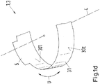
- Fig. 1c shows a cut for better understanding along the section line II according to Fig. 1a while using the Fig. 1d a section of the friction ring 1 according to Fig. 1a respectively
- Fig. 1b is shown in a perspective view in order to be able to see better the anti-rotation devices 5 extending along the friction ring axis 4 of the friction ring 1.
- the friction ring 1 according to the invention 1a to 1d is used in a synchronization unit 2 of a gear change transmission, in particular for a vehicle, in particular for a passenger car, a transporter or a truck.
- the friction ring 1 comprises a conical friction ring body 3 with an inner friction surface 301 and an outer installation surface 302, which is preferably designed as a further friction surface, and each delimit the friction ring body 3 in a radial circumferential direction U running perpendicular to an axial friction ring axis 4.
- the inner friction surface 301 extends at a predeterminable friction angle ⁇ 1 and the outer installation surface 302 at a predeterminable installation angle ⁇ 2, each conically along the friction ring axis 4, the friction angle ⁇ 1 being different from the installation angle ⁇ 2 according to the present invention.
- the installation angle ⁇ 2 is particularly preferably greater than the friction angle ⁇ 1 .
- the friction angle ⁇ 1 it is also possible for the friction angle ⁇ 1 to be greater than the installation angle ⁇ 2 .
- the friction ring body 3 in this special exemplary embodiment is a segmented friction ring body 3 which comprises a plurality of separate friction ring segments 31, 32, 33, in the present special exemplary embodiment thus three friction ring segments 31, 32, 33, which are arranged in an annular arrangement form the friction ring body 3 in such a way that the friction ring body 3 in the installed state in a first expanded configuration according to FIG Fig. 1a a first radius R 1 and in a second contracted configuration according to Fig. 1b has a second radius R 2 .
- a friction ring 1 according to the invention can also be constructed from a different number of friction ring segments 31, 32, 33, 34, for example as shown in FIG Fig. 2a and Fig. 2b shown by way of example, can also be constructed from four friction ring segments 31, 32, 33, 34, or, for example, can also be constructed from only two or more than four friction ring segments 31, 32, 33, 34.
- At least one anti-rotation device 5 is provided on the friction ring body 3 and, according to a first aspect of the invention, extends along the friction ring axis 4, which can be seen particularly clearly from FIG Fig. 1d can see.
- Fig. 2a and Fig. 2b show the already mentioned other exemplary embodiment of a friction ring 1 designed according to a second aspect of the invention, in which the anti-rotation device 5 extends essentially perpendicular to the friction ring axis 4.
- the number of anti-rotation devices 5 may differ depending on the exemplary embodiment and any number of anti-rotation devices 5 may be provided.
- a friction coating in particular a friction coating in the form of a carbon friction lining, which is not explicitly shown in the figures for reasons of clarity, can be provided on the friction surface 301 and / or on the installation surface 302 can serve to at least partially compensate for a resulting high mechanical and / or thermal load on the friction pairing.
- the friction ring 1 is particularly advantageously a steel stamped part or sheet metal part, which in particular makes industrial mass production particularly simple or inexpensive.
- the invention further relates to a synchronization unit 2 with a friction ring 1, as shown schematically on the basis of the Fig. 3 is shown as an example.
- the synchronization unit 2 in addition to the friction ring 1 according to the invention, in a manner known per se, it further comprises a sliding sleeve 6, a synchronizer ring 7, and a gear wheel 8, the aforementioned components being arranged coaxially with the friction ring axis 4 such that in the operating state, the synchronizing ring 7 is moved together with the The friction ring 1 can be displaced along the friction ring axis 4 in the direction of the gear wheel 8, so that the inner friction surface 301 of the friction ring body 3 can be brought into engagement with the gear wheel 8.
- the synchronizer ring 2 is in Fig. 3 made of stamped steel of conventional design.
- the cone of the synchronizer ring 7 has the same large internal angle ⁇ 2 , that is to say identical to the installation angle ⁇ 2 of the friction ring 1, the synchronizer ring 7 having coupling pockets for the segmented friction ring 1 which are known per se and are not shown in detail.
- the segmented friction ring 1 according to Fig. 3 is in three equally large friction ring segments 31, 32, 33, which for reasons of clarity in Fig. 3 is not shown in detail.
- the friction ring 1 has the installation surface 302 with the installation angle ⁇ 2 , the installation surface 302 being used as the separating surface.
- the inner cone of the friction ring 1 is formed by the friction surface 301 with the friction angle ⁇ 1 , where ⁇ 1 ⁇ 2 applies. This inner conical surface, that is to say the friction surface 301, is used for synchronization.
- the synchronizer ring 7 In the operating state, the synchronizer ring 7 is displaced axially in the direction of the gear wheel 8, which is designed as a gear wheel, and thus the three friction ring segments 31, 32, 33 of the friction ring 1 are also detected by the angle ⁇ 2 .
- the synchronizer ring 7 and the segmented friction ring 1 are then moved together at the same time and engage with the inner cone, that is to say the friction surface 301 with the friction angle ⁇ 1 , on the gear wheel 8, which also has a corresponding counter cone with the cone angle ⁇ 1 .
- the synchronizer ring 7 can then control and index like a conventional synchronizer ring 7.
- the teeth of the sliding sleeve 6 are in contact with the teeth of the synchronizer ring 7 and thus, due to the differential speed, generate a torque between the segmented friction ring 1 and the gear wheel 8.
- option 1 the friction surface or torque generation on the inner cone of the segments with the small angle has ⁇ 1 .
- the large release angle ⁇ 2 is on the outer conical surface of the segments.
- the friction surface on the outer cone of the segments has the small angle ⁇ 1 .
- the large release angle ⁇ 2 is on the inner conical surface of the segments, with option 1 being the preferred concept in practice.
- the invention also relates to a gear change transmission for a vehicle, in particular for a passenger car, a transporter or a truck with a friction ring 1 or a synchronization unit 2 as described in detail above.
Landscapes
- Engineering & Computer Science (AREA)
- General Engineering & Computer Science (AREA)
- Mechanical Engineering (AREA)
- Mechanical Operated Clutches (AREA)
Description
- Die Erfindung betrifft einen Reibring für eine Synchronisiereinheit eines schaltbaren Zahnräderwechselgetriebes, eine Synchronisierungseinheit, sowie ein Zahnräderwechselgetriebe für ein Fahrzeug gemäss dem Oberbegriff der unabhängigen Ansprüche.
- Synchronringe dienen in einem mechanischen schaltbaren Zahnräderwechselgetriebe, z.B. in Fahrzeuggetrieben dazu, die während eines Gangwechsels auftretenden Relativgeschwindigkeiten zwischen Gangrad und Getriebewelle aneinander anzugleichen. Die Synchronisation wird dabei durch Reibung zwischen den entsprechenden Reibpartner erzielt. Die Funktionsweise solcher Getriebe und der Ablauf des Synchronisationsvorgangs sind an sich bekannt und brauchen dem Fachmann hier nicht mehr näher erläutert zu werden.
- Zum Schutz gegen vorzeitigen Verschleiss und / oder zur Verbesserung der Reibcharakteristik ist es bekannt, die Reibflächen von Synchronringen, die in der Regel aus einem Metall oder einer Metallegierung, wie beispielsweise aus Messing oder Stahl gefertigt sind, mit einer Reibschicht zu versehen. Dabei sind ganz verschiedene Typen von Reibschichten im Gebrauch, z.B. thermische Spritzschichten aus Molybdän, Carbon-Reibschichten oder Reibschichten aus anderen Materialien.
- Synchronisierungseinheiten für Zahnräderwechselgetriebe bzw. einzelne Komponenten von Synchronisierungseinheiten sind im Stand der Technik vielfältig und ausführlich beschrieben.
- So sind beispielweise Handschalt- und Doppelkupplungsgetriebe heutzutage in vielen Anwendungen die dominierenden Getriebetypen im Klein- und Mittelklassewagensegment insbesondere bei Front-Quer-Antrieben. Die Schaltcharakteristik dieser Getriebearten wird wesentlich durch die Synchronisierung bestimmt, deren Prinzip heute wie damals auf dem sogenannten Borg-Warner-Konzept beruht, das erstmals ausführlich in der
EP 1 507 091 B1 beschrieben wurde. Eine hohe Effizienz zur Realisierung kurzer Schaltzeiten bei niedrigen Schaltkräften und ein hoher Schaltkomfort sind immer wichtiger werdende Anforderungen an das System Synchronisierung. - Die geometrische Auslegung einer klassischen Borg-Warner-Synchronisierung hinsichtlich Effizienz und Schaltkomfort wird dabei durch einen Zielkonflikt bestimmt. Eine hohe Effizienz wird durch kleine Konuswinkel der Reibpaarung erreicht, der Verstärkungseffekt des Konus erzeugt hohe Synchronisierungsmomente trotz niedriger Betätigungskräfte. Demgegenüber setzt der Selbsthemmungseffekt, der ein Lösen der Reibflächen verhindert und den Schaltkomfort substanziell und spürbar für den Fahrer beeinträchtigt, der Minimierung des Konuswinkels eine natürliche Grenze. Die Optimierung einer Synchronisierung ist daher immer ein Kompromiss zwischen Effizienz und Schaltkomfort.
- Die dominierende Art von Synchronisierungen, die innerhalb der dem Getriebefachmann bestens bekannten MT-, AMT- und DCT-Getrieben genutzt werden, sind im konventionellen BorgWarner Design gemäss
EP 1 507 091 B1 ausgeführt. Aufgrund der ständigen Forderungen nach höheren Schaltleistungen und Drehmomenten, wurden auf dieser Basis anspruchsvollen Multiple-Konus-System-Synchronisierungen mit doppelten, dreifachen und in bestimmten Nischen-Anwendungen auch mit vervierfachen Reibflächen entwickelt. Diese hoch entwickelten Synchronmodule haben erhöhte Leistungs- und Momentenkapazitäten, aufgrund der mehrfachen Reibungsflächen und der hohen Reibematerialeigenschaften. Nichtsdestotrotz erhöhen sie auch die Komplexität, Kosten und nicht zuletzt auch das Gewicht der entsprechenden Getriebe. - Obwohl diese Arten von Synchronisierungen kontinuierlich, in Bezug auf die Fertigungsprozesse und Leistung, optimiert wurden, bleibt bis heute ein Designkonflikt.
- Eines der kritischsten Merkmale bei der Konstruktion von Synchronisierungen ist nämlich die Auslegung der Winkel der beteiligten konischen Reibflächen. Dieses wichtige Merkmal bestimmt zwei Hauptfunktionen:
Zum einen die Synchronleistung. Der Konuswinkel ist nämlich einer der wichtigsten Faktoren bei der Bestimmung des Reibmoments in Kombination mit dem Durchmesser des Konus und des Reibwerts zwischen dem Zahnrad und der Konusfläche des Synchronrings. Die Reduzierung der Konuswinkel erhöht das Drehmoment. Dadurch wird die Schaltkraft reduziert und kürzere Synchronisationszeiten können realisiert werden. - Auf der anderen Seite aber auch die Schaltqualität in Bezug auf das Lösen der Reibkonen am Ende der Synchronisation. Der Konuswinkel hat einen großen Einfluss bei der Bestimmung der Qualität des Schaftgefühls des Fahrers. Ein zu kleiner Winkel, kann ungünstige Auswirkungen erzeugen, wie z. B. Versperren oder zweite Druckpunkte.
- Um eine maximale Schaltleistung zu erzielen, ist ein kleiner Konuswinkel erforderlich. Um das Design im Hinblick auf die Schaltqualität zu optimieren, ist dagegen ein großer Konuswinkel erforderlich. Daraus resultiert somit für konventionelle Synchronisierungen einen Zielkonflikt bezüglich des Designs.
- Daher gibt es im Stand der Technik je nach Anforderung Unterschiede bei der Designauslegung der verschiedenen Getriebetypen. Die Synchronleistung steht beispielweise bei DCT Getrieben im Vordergrund und weniger die Schaltqualität. Bei manuell geschalteten Getrieben wird dagegen versucht eine ausgewogene Balance zwischen Leistung und Schaltqualität zu erreichen.
- Wie bereits erwähnt, müssen dabei die Momentenkapazitäten erhöht werden, um die Synchronleistung zu erhöhen, in Bezug auf niedrigere Schaltkräfte und kürzere Schaltzeiten. Jedoch jede Synchronisierung wird durch das Design und Anwendung auf eine erzielbare Leistung begrenzt, sei es durch den Durchmesser, Reibwert, oder den Mindest-Konuswinkel.
- Um die Leistung oder Momentenkapazitäten zu erhöhen, kann der Konstrukteur bisher im Allgemeinen nur zusätzliche Reiboberflächen hinzufügen, d.h. vom Einfachkonus auf Mehrfachkonen. Aber auch bei zusätzlichen Reibflächen, gibt es dennoch funktionale Grenzen der Momentenkapazitäten aufgrund der Konuswinkel.
- Während der eigentlichen Synchronisierung steuert die angewendete Kraft (F) den Synchronisierer mit den Reaktionskräften Fax und Frad an. Mit Hilfe eines Koordinatensystems kann dies jetzt in FR (Reibung) und FN (Normalkraft) aufgeteilt werden, wobei der Winkel ρ = tan-1 µ ist und α der Konuswinkel ist. Damit das System im Gleichgewicht ist, muss eine Kraft FU, die die Umfangskraft im Material ist, der Radialkraft Frad entgegenwirken.
- Während des Lösens, wird eine zusätzliche Kraft zur Kraft FU benötigt, um den Ring vom Gangradkonus zu lösen. Die Reibungskraft FR ist jetzt in der entgegengesetzten Richtung vom Synchronierungsvorgang und α <tan-1 <tan-1 µ (µ ist der statische Reibkoeffizient). Dieser Effekt wird Selbsthemmung genannt und beeinträchtigt negative die Schaltqualität. Der funktionelle Grenzwert für alle Synchronisierungen ist α > tan-1 µ.
- Wenn der Konuswinkel innerhalb des Systems weiter reduziert wird, um die Momentenkapazitäten zu verbessern, dann erhöht sich auch das Niveau an zweiten Druckpunkten, aufgrund von Selbsthemmung. Dadurch wird die Schaltung als unangenehm empfunden. In extremen Fällen kann es sogar dazu führen, dass es zum vollständigen Blockieren kommt.
- In der
EP 1199489 A1 wird ein Reibring einer Synchronisiereinrichtung beschrieben. Der Reibring weist eine äussere und eine innere Reibfläche für einen Reibkontakt mit einem äusseren und einem inneren Synchronring der Synchronisiereinrichtung auf. Der Reibring ist so ausgestaltet, dass die Reibungsbelastung an der äusseren und der inneren Reibfläche in etwa gleich gross sind. Dazu ist eine Unterbrechung auf dem Umfang des Reibrings vorgesehen und die beiden Reibflächen weisen unterschiedliche Kegelwinkel auf. - Die Aufgabe der Erfindung ist es daher, einen verbesserten Synchronisierungsmechanismus und die dazu notwendigen Komponenten zur Verfügung zu stellen, so dass die Eingangs beschriebenen, aus dem Stand der Technik bekannten Nachteile vermieden werden können. Insbesondere soll durch die vorliegende Erfindung der Zielkonflikt hinsichtlich Effizienz und Schaltkomfort aufgelöst werden. D.h. durch die Erfindung soll einerseits eine hohe Effizienz der Reibpaarung erreicht werden, also ein Verstärkungseffekt erzielt werden, so dass der Konus hohe Synchronisierungsmomente trotz niedriger Betätigungskräfte erzeugen kann. Anderseits soll gleichzeitig der Selbsthemmungseffekt, der ein Lösen der Reibflächen verhindert oder zumindest erschwert und den Schaltkomfort substanziell und spürbar für den Fahrer beeinträchtigt, möglichst vermieden bzw. auf ein angemessenes Mass reduziert werden. Aufgabe der Erfindung ist somit eine Optimierung der Synchronisierung ohne dass die aus dem Stand der Technik notwendigen Kompromisse zwischen Effizienz und Schaltkomfort in Kauf genommen werden müssen.
- Die diese Aufgaben lösenden Gegenstände der Erfindung sind durch die Merkmale des unabhängigen Anspruchs gekennzeichnet.
- Die abhängigen Ansprüche beziehen sich auf besonders vorteilhafte Ausführungsformen der Erfindung.
- Die Erfindung betrifft somit einen Reibring für eine Synchronisierungseinheit eines Zahnräderwechselgetriebes, welcher Reibring einen konischen Reibringkörper mit einer inneren Reibfläche und eine, bevorzugt als weitere Reibungsfläche ausgebildeten äussere Einbaufläche umfasst, die den Reibringkörper in einer senkrecht zu einer axialen Reibringachse verlaufenden radialen Umfangsrichtung jeweils begrenzen, und sich die innere Reibfläche unter einem vorgebaren Reibwinkel und die äussere Einbaufläche unter einem vorgebaren Einbauwinkel jeweils konisch entlang der Reibringachse erstrecken. Erfindungsgemäss ist der Reibwinkel verschieden vom Einbauwinkel.
- Wesentlich für die Erfindung ist es, dass der Reibring derart ausgestaltet ist, dass der Reibwinkel verschieden vom Einbauwinkel ist. Dadurch wird erstmals der Zielkonflikt hinsichtlich Effizienz und Schaltkomfort, wie er seit langem im Stand der Technik besteht, zuverlässig aufgelöst. D.h. durch die Erfindung wird einerseits eine hohe Effizienz der Reibpaarung erreicht, also ein Verstärkungseffekt erzielt, so dass der Konus hohe Synchronisierungsmomente trotz niedriger Betätigungskräfte erzeugen kann. Anderseits wird gleichzeitig der bekannte schädliche Selbsthemmungseffekt, der ein Lösen der Reibflächen verhindert oder zumindest erschwert und den Schaltkomfort substanziell und spürbar für den Fahrer beeinträchtigt, durch die Erfindung praktisch vollständig vermieden. Somit ist es durch die Erfindung erstmals möglich, dass die aus dem Stand der Technik notwendigen Kompromisse zwischen Effizienz und Schaltkomfort nicht mehr in Kauf genommen werden müssen.
- Der neuartige erfindungsgemässe Ansatz diesen Zielkonflikt aufzulösen, ist die räumliche Trennung der Funktion "Synchronisierungsmoment erzeugen" und "Reibpaarung lösen", die bisher in ein und derselben Reibpaarung vereint waren. Die Trennung wird durch einen, bevorzugt aber nicht notwendig segmentierten Reibring mit unterschiedlichen Konuswinkeln am Innen- und Außendurchmesser erreicht. Ein Durchmesser erzeugt kraftschlüssig das Synchronisierungsmoment, der andere Durchmesser sorgt für ein zuverlässiges Lösen des Kraftschlusses. Somit erfolgt erfindungsgemäss eine unabhängige Optimierung der beiden Funktionen hinsichtlich ihrer spezifischen Anforderungen. Durch die Erfindung wurde damit erstmals festgestellt, dass es möglich ist, durch die räumliche Trennung der Funktionen der Synchronisationsleistung (Generierung geringer Schaltkräfte und kurzer Schaltzeiten) von der Schaltqualität (zweiter Druckpunkt und Selbsthemmungseffekte) den bekannten Zielkonflikt zu lösen. Beide Funktionen sind im klassischen, aus dem Stand der Technik bekannten Design direkt miteinander über den Konuswinkel verbunden, was zu den geschilderten, bisher unvermeidbaren Optimierungsproblemen geführt hatte.
- Dabei werden durch die Erfindung auch weitere wesentliche Voraussetzungen erfüllt, die in bestimmten Fällen wesentlich sein, um das gewünschte Ergebnis zu erreichen.
- Das erfindungsgemässe Design mit einem vom Reibwinkel verschiedenen Einbauwinkel nimmt das gesamte Spektrum der Momentenkapazitäten und Schaltkomfort Anforderungen heutiger konventioneller Synchronisierungen auf. Die erfindungsgemässen Komponenten der Synchronisiereinheit passen in den zur Verfügung stehenden Bauraum. Die Herstellung erfindungsgemässer Komponenten ist auch aus Stahlstanzteilen möglich, die damit sehr einfach und kostengünstig herstellbar sind. Die Komponenten der vorliegenden Erfindung, insbesondere der Reibring sind geeignet für die Anwendung und Beschichten mit bestehenden Technologien und Prozessen, sowie den zur Verfügung stehenden Reibmaterialien, wobei gleichzeitig die Produktions- und Stückkosten zumindest, gleich oder in der Praxis oft niedriger als bei den heute bekannten Mehrfachsynchronisierungen ausfallen.
- Der innovative Lösungsansatz der vorliegenden Erfindung, nämlich die beiden Funktionen Synchronisation und Lösen räumlich zu trennen, wird im Wesentlichen durch einen kleinen Winkel zur konischen Reibfläche, der die Leistung oder die Momentenkapazitäten verbessert und durch einen großen Winkel zum Lösen des Systems, wodurch die negativen Auswirkungen der Selbsthemmung, die zu einer schlechten Schaltqualität führen, erzielt.
- In einem besonders bevorzugten Ausführungsbeispiel der vorliegenden Erfindung wird ein weiterer kritischer Faktor berücksichtigt, nämlich die Kräfte in Umfangsrichtung (FU) innerhalb des Reibrings. Durch den kleinen Winkel ist es je nach Anwendung und Ausführungsform nämlich möglich, dass es zur Selbsthemmung auf dem Zahnradkonus kommen kann. Um dieses Risiko auszuschließen, kann der Reibring auch segmentiert werden.
- Wie an sich bekannt ist, wird während der Synchronisation der Synchronring mit einer externen Kraft F belastet. Das erzeugt externe radiale Kräfte, die auf das Segment Frad wirken. Die Reaktionskräfte Fax und Frad an der Reibfläche sind im Gleichgewicht und sind die gleichen wie bei einer herkömmlichen Synchronisierung. Nach der Synchronisation, wenn die Schiebemuffenzähne die Zähne des Synchronrings passieren, wird die externe Kraft dann aufgelöst. Der große Winkel trennt durch α2 > tan-1 µ2 und daher gibt es keine Frad, die auf den Segmenten wirken und da es kein Material Beanspruchung innerhalb der Segmente durch das Reibelement ist kein fester Ring, trennt sich die kleinen Winkel, da keine internen oder äußere Kräfte auf sie wirken.
- Die Erfindung bezieht sich weiter auf ein Schaltgetriebe für ein Fahrzeug, insbesondere für einen Personenkraftwagen, einen Transporter oder einen Lastkraftwagen mit einem Synchronring nach einem der vorangehenden Ansprüche.
- Im Folgenden wird die Erfindung an Hand der schematischen Zeichnung näher erläutert. Es zeigen:
- Fig. 1a
- einen erfindungsgemässen Reibring mit segmentiertem Reibringkörper in einer expandierten Konfiguration;
- Fig. 1b
- den Reibring gemäss
Fig. 1a in einer zusammengezogenen Konfiguration; - Fig. 1c
- einen Schnitt entlang der Schnittlinie I-I gemäss
Fig. 1a ; - Fig. 1d
- einen Abschnitt des Rebrings gemäss
Fig. 1a bzw.Fig. 1b in perspektivischer Ansicht; - Fig. 2a
- ein zweites Ausführungsbeispiel eines erfindungsgemässen segmentierten Reibrings mit radialen Verdrehsicherungen;
- Fig. 2b
- einen Abschnitt des Rebrings gemäss
Fig. 2a in perspektivischer Ansicht; - Fig. 3
- ein einfaches Ausführungsbeispiel einer erfindungsgemässen Synchronisierungseinheit;
- Die
Fig. 1a und Fig. 1b bzw. dieFig. 1c und1d zeigen in einer schematischen Darstellung ein und dasselbe sehr einfache Ausführungsbeispiel eines erfindungsgemässen Reibrings mit segmentiertem Reibringkörper, wobei der Reibring im Folgenden gesamthaft mit dem Bezugszeichen 1 bezeichnet wird. -
Fig. 1a zeigt den Reibring 1 dabei in einer expandierten Konfiguration, währendFig. 1b denselben Reibring in einer zusammengezogenen Konfiguration zeigt.Fig. 1c zeigt zum besseren Verständnis einen Schnitt entlang der Schnittlinie I-I gemässFig. 1a , während anhand derFig. 1d ein Abschnitt des Reibrings 1 gemässFig. 1a bzw.Fig. 1b in perspektivischer Ansicht gezeigt ist, um die sich entlang der Reibringachse 4 des Reibrings 1 erstreckenden Verdrehsicherungen 5 besser sehen zu können. - Der erfindungsgemässe Reibring 1 gemäss den
Fig. 1a bis Fig. 1d dient zur Verwendung in einer Synchronisierungseinheit 2 eines Zahnräderwechselgetriebes, insbesondere für ein Fahrzeug, im Speziellen für einen Personenkraftwagen, einen Transporter oder einen Lastkraftwagen. Der Reibring 1 umfasst einen konischen Reibringkörper 3 mit einer inneren Reibfläche 301 und einer, bevorzugt als weitere Reibungsfläche ausgebildeten äusseren Einbaufläche 302, die den Reibringkörper 3 in einer senkrecht zu einer axialen Reibringachse 4 verlaufenden radialen Umfangsrichtung U jeweils begrenzen. Dabei erstreckt sich die innere Reibfläche 301 unter einem vorgebaren Reibwinkel α1 und die äussere Einbaufläche 302 unter einem vorgebaren Einbauwinkel α2 jeweils konisch entlang der Reibringachse 4, wobei gemäss der vorliegenden Erfindung der Reibwinkel α1 verschieden vom Einbauwinkel α2 ist. - Wie insbesondere der
Fig. 1c deutlich zu entnehmen ist, ist der Einbauwinkel α2 besonders bevorzugt grösser ist als der Reibwinkel α1. Dabei ist es im Prinzip auch möglich, dass der Reibwinkel α1 grösser ist als der Einbauwinkel α2. - Wie anhand der
Fig. 1a undFig. 1 deutlich zu erkennen ist, ist der Reibringkörper 3 in diesem speziellen Ausführungsbeispiel ein segmentierter Reibringkörper 3 ist, der eine Mehrzahl von separaten Reibringsegmenten 31, 32, 33, im vorliegenden speziellen Ausführungsbeispiel also drei Reibringsegmenten 31, 32, 33 umfasst, die in einer ringförmigen Anordnung den Reibringkörper 3 derart bilden, dass der Reibringkörper 3 im Einbauzustand in einer ersten expandierten Konfiguration gemässFig. 1a einen ersten Radius R1 und in einer zweiten zusammengezogenen Konfiguration gemässFig. 1b einen zweiten Radius R2 hat. - Es versteht sich dabei, dass ein erfindungsgemässer Reibring 1 auch aus einer anderen Anzahl von Reibringsegmenten 31, 32, 33, 34 aufgebaut sein kann, z.B. wie anhand der
Fig. 2a und Fig. 2b exemplarisch gezeigt auch aus vier Reibringsegmenten 31, 32, 33, 34 aufgebaut sein kann, oder auch zum Beispiel nur aus zwei oder mehr als vier Reibringsegmenten 31, 32, 33, 34 aufgebaut sein kann. - Am Reibringkörper 3 ist dabei mindestens eine Verdrehsicherung 5 vorgesehen, die sich nach einem ersten Aspekt der Erfindung entlang der Reibringachse 4 erstreckt, was man besonders deutlich aus der
Fig. 1d ersehen kann. - Die
Fig. 2a und Fig. 2b zeigen dabei das bereits erwähnte andere Ausführungsbeispiel eines nach einem zweiten Aspekt der Erfindung ausgestalteten Reibrings 1, bei welchem sich die Verdrehsicherung 5 im Wesentlichen senkrecht zur Reibringachse 4 erstreckt. - Es versteht sich dabei von selbst, dass unabhängig von den gezeigten speziellen Ausführungsbeispielen die Anzahl der Verdrehsicherungen 5 je nach Ausführungsbeispiel verschieden sein und eine beliebige Anzahl an Verdrehsicherungen 5 vorgesehen sein können.
- Besonders vorteilhaft kann an der Reibfläche 301 und / oder an der Einbaufläche 302 eine in den Figuren aus Gründen der Übersichtlichkeit nicht explizit dargestellte Reibbeschichtung, insbesondere ein Reibbeschichtung in Form eines Karbon Reibbelags vorgesehen sein, die unter anderem dazu dienen kann, eine resultierende hohe mechanische und / oder thermische Belastung der Reibpaarung zumindest teilweise zu kompensieren.
- Besonders Vorteilhaft ist der Reibring 1 dabei ein Stahlstanzteil oder Blechumformteil, was insbesondere eine industrielle Massenfertigung besonders einfach oder kostengünstig macht.
- Die Erfindung betrifft weiter eine Synchronisierungseinheit 2 mit einem Reibring 1, wie sie schematisch anhand der
Fig. 3 beispielhaft dargestellt ist. - Die Synchronisierungseinheit 2 gemäss
Fig. 3 umfasst neben dem erfindungsgemässen Reibring 1 in an sich bekannter Weise weiter eine Schiebemuffe 6, einen Synchronring 7, sowie ein Gangrad 8, wobei die vorgenannten Komponenten derart koaxial zur Reibringachse 4 angeordnet sind, dass im Betriebszustand der Synchronring 7 durch die Schiebemuffe 6 gemeinsam mit dem Reibring 1 entlang der Reibringachse 4 in Richtung zum Gangrad 8 verschiebbar ist, so dass die innere Reibfläche 301 des Reibringkörpers 3 mit dem Gangrad 8 in Eingriff bringbar ist. - Der Synchronring 2 ist dabei in
Fig. 3 aus gestanztem Stahl konventioneller Bauart gefertigt. Der Konus des Synchronrings 7 hat dabei denselben großen inneren Winkel α2, also identisch zum Einbauwinkel α2 des Reibring 1, wobei der Synchronring 7 an sich bekannte, nicht näher dargestellte Kopplungstaschen für den segmentierten Reibring 1 hat. Der segmentierte Reibring 1 gemässFig. 3 ist in drei gleich große Reibringsegmente 31, 32, 33, was aus Gründen der Übersichtlichkeit inFig. 3 nicht im Detail dargestellt ist. Der Reibring 1 hat gemäss der Erfindung dabei die Einbaufläche 302 mit dem Einbauwinkel α2, wobei die Einbaufläche 302 als Trennfläche verwendet wird. Der Innenkonus des Reibrings 1 wird durch die Reibfläche 301 mit Reibwinkel α1 gebildet, wobei α1 < α2 gilt. Diese innere Konusfläche, also die Reibfläche 301 wird zum Synchronisieren genutzt. - Im Betriebszustand wird der Synchronring 7 axial in Richtung zum Gangrad 8, das als Zahnrad ausgebildet ist, verschoben und damit werden auch die drei Reibringsegmente 31, 32, 33 des Reibrings 1 durch den Winkel α2 erfasst. Der Synchronring 7 und der segmentierte Reibring 1 werden dann zusammen gleichzeitig bewegt und mit dem Innenkonus, also der Reibfläche 301 mit Reibwinkel α1, auf das Gangrad 8, das ebenfalls einen entsprechenden Gegenkonus mit Konuswinkel α1 hat, eingreifen. Der Synchronring 7 kann dann wie ein herkömmlicher Synchronring 7 ansteuern und indexieren. Die Zähne der Schiebemuffe 6 sind im Kontakt mit den Zähnen des Synchronrings 7 und erzeugen so, durch die Differenzdrehzahl, ein Moment zwischen dem segmentierten Reibring 1 und dem Gangrad 8.
- Nach der Synchronisation, wenn das Differenzdrehzahl Null ist, wird die Schiebemuffe 6 axial bewegt, die Synchronringzähne passieren und dann im Kontakt mit den Zähnen der Flanken des Gangrades 8 sein. Aufgrund dessen gibt es keine Axialkraft mehr auf dem Synchronring 7. Der große Winkel a2 wird das System trennen (Winkel > tan-1 µ). Dies resultiert durch die Eliminierung der Kräfte in Umfangsrichtung des segmentierten Reibrings 1. An diesem Punkt brechen der Synchronring 7 und der segmentierte Reibring 1 vom Gangrad 8 los. Anschließend kann die Schiebemuffe 6 das Gangrad 8 passieren. Die Schaltung ist dann vollständig im Eingriff.
- Dabei sind im Speziellen mindestes zwei verschiedene Optione 1 und Option 2 möglich. Bei Option 1 hat die Reibfläche oder Momentenerzeugung auf dem Innenkonus der Segmente mit dem kleinen Winkel α1. Der große Lösewinkel α2 ist auf der äußeren Konusfläche der Segmente.
- Bei Option 2, hat die Reibfläche auf dem Außenkonus der Segmente den kleinen Winkel α1. Der große Lösewinkel α2 ist auf der inneren Konusfläche der Segmente, wobei in der Praxis die Option 1 das bevorzugte Konzept ist. Schliesslich betrifft die Erfindung auch ein Zahnräderwechselgetriebe für ein Fahrzeug, insbesondere für einen Personenkraftwagen, einen Transporter oder eine Lastkraftwagen mit einem Reibring 1 oder einer Synchronisierungseinheit 2 wie zuvor eingehend beschrieben.
- Es versteht sich, dass alle in dieser Anmeldung explizit diskutierten Ausführungsbeispiele nur exemplarisch für die Erfindung zu verstehen sind und insbesondere auch alle geeigneten Kombinationen, die für spezielle Anwendungen vorteilhaft eingesetzt werden können, bzw. alle dem Fachmann nahe liegenden Weiterbildungen durch die Erfindung erfasst sind.
Claims (9)
- Reibring für eine Synchronisierungseinheit (2) eines Zahnräderwechselgetriebes, bei welchem der Reibring einen konischen Reibringkörper (3) mit einer inneren Reibfläche (301) und eine äussere Einbaufläche (302) umfasst, die den Reibringkörper (3) in einer senkrecht zu einer axialen Reibringachse (4) verlaufenden radialen Umfangsrichtung (U) jeweils begrenzen, wobei sich die innere Reibfläche (301) unter einem vorgebaren Reibwinkel (α1) und die äussere Einbaufläche (302) unter einem vorgebaren Einbauwinkel (α2) jeweils konisch entlang der Reibringachse (4) erstrecken, dass der Reibwinkel (α1) verschieden vom Einbauwinkel (α2) ist dadurch gekennzeichnet, dass am Reibringkörper (3) eine Verdrehsicherung (5) vorgesehen ist, welche bezüglich der inneren, sich konisch verjüngenden Reibfläche (301), auf der Seite mit dem kleineren Durchmesser angebracht ist und/oder sich in Richtung der Reibringachse auf der äusseren Einbaufläche (302) im Wesentlichen senkrecht zur Reibringachse erstreckt.
- Reibring nach Anspruch 1, wobei der Einbauwinkel (α2) grösser ist als der Reibwinkel (α1).
- Reibring nach einem der Ansprüche 1 oder 2, wobei der Reibringkörper (3) ein segmentierter Reibringkörper (3) ist, der eine Mehrzahl von separaten Reibringsegmenten (31, 32, 33, 34) umfasst, die in einer ringförmigen Anordnung den Reibringkörper (3) derart bilden, dass der Reibringkörper (3) im Einbauzustand in einer ersten expandierten Konfiguration einen ersten Radius (R1) und in einer zweiten zusammengezogenen Konfiguration einen zweiten Radius (R2) hat.
- Reibring nach einem der vorangehenden Ansprüche, wobei die äussere Einbaufläche (302) als weitere Reibungsfläche ausgebildet ist.
- Reibring nach einem der vorangehenden Ansprüche, wobei an der Reibfläche (301) und / oder an der Einbaufläche (302) eine Reibbeschichtung, insbesondere ein Reibbeschichtung in Form eines Karbon Reibbelags vorgesehen ist
- Reibring nach einem der vorangehenden Ansprüche, wobei der Reibring ein Stahlstanzteil oder ein Blechumformteil ist.
- Synchronisierungseinheit mit einem Reibring (1) nach einem der vorangehenden Ansprüche.
- Synchronisierungseinheit nach Anspruch 7, wobei die Synchronisierungseinheit weiter eine Schiebemuffe (6), einen Synchronring (7), sowie ein Gangrad (8) umfasst, die derart koaxial zur Reibringachse (4) angeordnet sind, dass im Betriebszustand der Synchronring (7) durch die Schiebemuffe (6) gemeinsam mit dem Reibring (1) entlang der Reibringachse (4) in Richtung zum Gangrad (8) verschiebbar ist, so dass die innere Reibfläche (301) des Reibringkörpers (3) mit dem Gangrad (8) in Eingriff bringbar ist.
- Zahnräderwechselgetriebe für ein Fahrzeug, insbesondere für einen Personenkraftwagen, einen Transporter oder einen Lastkraftwagen mit einem Reibring (1) oder einer Synchronisierungseinheit (2) nach einem der vorangehenden Ansprüche.
Priority Applications (1)
| Application Number | Priority Date | Filing Date | Title |
|---|---|---|---|
| EP13169504.1A EP2677187B1 (de) | 2012-06-18 | 2013-05-28 | Reibring, Synchronisierungseinheit, sowie ein Zahnräderwechselgetriebe für ein Fahrzeug |
Applications Claiming Priority (2)
| Application Number | Priority Date | Filing Date | Title |
|---|---|---|---|
| EP12172322 | 2012-06-18 | ||
| EP13169504.1A EP2677187B1 (de) | 2012-06-18 | 2013-05-28 | Reibring, Synchronisierungseinheit, sowie ein Zahnräderwechselgetriebe für ein Fahrzeug |
Publications (2)
| Publication Number | Publication Date |
|---|---|
| EP2677187A1 EP2677187A1 (de) | 2013-12-25 |
| EP2677187B1 true EP2677187B1 (de) | 2020-05-20 |
Family
ID=48463897
Family Applications (1)
| Application Number | Title | Priority Date | Filing Date |
|---|---|---|---|
| EP13169504.1A Active EP2677187B1 (de) | 2012-06-18 | 2013-05-28 | Reibring, Synchronisierungseinheit, sowie ein Zahnräderwechselgetriebe für ein Fahrzeug |
Country Status (4)
| Country | Link |
|---|---|
| US (1) | US9400019B2 (de) |
| EP (1) | EP2677187B1 (de) |
| JP (1) | JP6372875B2 (de) |
| CN (1) | CN103511496B (de) |
Cited By (1)
| Publication number | Priority date | Publication date | Assignee | Title |
|---|---|---|---|---|
| EP3112716B1 (de) * | 2015-06-26 | 2022-01-19 | Oerlikon Friction Systems (Germany) GmbH | Baueinheit für eine synchronisierungseinheit eines zahnräderwechselgetriebes |
Families Citing this family (12)
| Publication number | Priority date | Publication date | Assignee | Title |
|---|---|---|---|---|
| ES2663475T3 (es) | 2013-12-17 | 2018-04-12 | OERLIKON FRICTION SYSTEMS (GERMANY) GmbH | Anillo de fricción, anillo de sincronización, unidad de sincronización, así como una caja de cambios de velocidades para un vehículo |
| WO2015126809A1 (en) * | 2014-02-20 | 2015-08-27 | American Axle & Manufacturing, Inc. | Actuator for a driveline component |
| DE102015100869B4 (de) * | 2015-01-21 | 2016-10-13 | Hoerbiger Antriebstechnik Holding Gmbh | Verfahren zur Herstellung eines Synchronrings sowie Synchronring für synchronisierte Schaltgetriebe |
| CN104728295B (zh) * | 2015-04-07 | 2023-08-29 | 天津天海同步科技有限公司 | 汽车同步器总成 |
| BR102016021056A2 (pt) | 2015-10-07 | 2017-05-30 | OERLIKON FRICTION SYSTEMS (GERMANY) GmbH | Friction ring for a synchronization unit |
| EP3184839A1 (de) * | 2015-12-22 | 2017-06-28 | Oerlikon Friction Systems (Germany) GmbH | Synchronisierungseinheit für ein zahnräderwechselgetriebe |
| EP3252334B1 (de) | 2016-06-01 | 2019-07-24 | Oerlikon Friction Systems (Germany) GmbH | Baueinheit für eine synchronisierungseinheit eines zahnräderwechselgetriebes |
| EP3287656B1 (de) * | 2016-08-23 | 2019-03-20 | Oerlikon Friction Systems (Germany) GmbH | Synchronisierungseinrichtung, sowie ein zahnräderwechselgetriebe für ein fahrzeug |
| EP3287655B1 (de) | 2016-08-23 | 2019-03-20 | Oerlikon Friction Systems (Germany) GmbH | Synchronisierungseinrichtung, sowie ein zahnräderwechselgetriebe für ein fahrzeug |
| WO2018232698A1 (zh) * | 2017-06-22 | 2018-12-27 | 深圳市柔宇科技有限公司 | 阵列基板的制作设备及阵列基板的制作方法 |
| DE102017211425B4 (de) * | 2017-07-05 | 2021-06-24 | Audi Ag | Synchronisierelement für ein Getriebe, insbesondere eines Kraftfahrzeugs, Synchronisiereinrichtung mit zumindest einem solchen Synchronisierelement sowie Getriebe für ein Kraftfahrzeug |
| JP6977421B2 (ja) * | 2017-09-13 | 2021-12-08 | いすゞ自動車株式会社 | 変速機の同期装置 |
Citations (3)
| Publication number | Priority date | Publication date | Assignee | Title |
|---|---|---|---|---|
| US20080067026A1 (en) * | 2006-09-15 | 2008-03-20 | Sulzer Euroflamm Germany Gmbh | Synchronizer ring |
| WO2008155173A1 (de) * | 2007-06-19 | 2008-12-24 | Schaeffler Kg | Synchronisiereinrichtung |
| US20090314599A1 (en) * | 2008-06-18 | 2009-12-24 | Ulf Christoffer | Synchronizing Ring And Gear Changing Transmission For A Vehicle |
Family Cites Families (30)
| Publication number | Priority date | Publication date | Assignee | Title |
|---|---|---|---|---|
| US3414098A (en) * | 1966-10-05 | 1968-12-03 | Borg Warner | Positive clutch with multiple friction synchronizing disks |
| FR2513631A1 (fr) | 1981-09-29 | 1983-04-01 | Rhone Poulenc Spec Chim | Procede d'hydrolyse d'ethers aryl-aliphatiques |
| DE3519811C2 (de) | 1985-06-03 | 1994-05-11 | Borg Warner Automotive Gmbh | Träger für einen Synchronisierring |
| DE3519810C2 (de) | 1985-06-03 | 1993-12-23 | Borg Warner Automotive Gmbh | Träger mit geringer Materialstärke für einen Synchronisierring |
| US4732247A (en) * | 1987-01-21 | 1988-03-22 | Chrysler Motors Corporation | Triple cone synchronizer with servo action |
| US6065579A (en) | 1994-09-30 | 2000-05-23 | Select Powertrain Technologies Corp. | Synchronizer blocker rings used in manual transmissions |
| AT401555B (de) | 1994-12-13 | 1996-10-25 | Hoerbiger & Co | Synchronisierungseinrichtung für schaltgetriebe |
| SE502802C2 (sv) | 1994-12-21 | 1996-01-15 | Saab Automobile | Anordning för förhindrande av skrammel i en synkroniserad växellåda |
| US5560461A (en) * | 1995-02-24 | 1996-10-01 | Dana Corporation | Multiple cone synchronizer for vehicle transmission |
| FR2751712B1 (fr) | 1996-07-24 | 1998-10-30 | Valeo | Bague de synchronisation pour un synchroniseur de boite de vitesses |
| DE19719618B4 (de) | 1997-05-09 | 2005-08-04 | Ina-Schaeffler Kg | Synchronring, der aus mehreren Einzelteilen zusammengefügt ist |
| JPH11223225A (ja) * | 1997-12-03 | 1999-08-17 | Nippon Seiko Kk | シンクロナイザリングの製造方法 |
| DE19853856A1 (de) | 1998-11-23 | 2000-05-25 | Schaeffler Waelzlager Ohg | Spanlos umgeformter Synchronring |
| DE19853896A1 (de) * | 1998-11-23 | 2000-05-25 | Schaeffler Waelzlager Ohg | Anordnung und Ausführung von Synchronringen als spanlos geformte Blechteile |
| DE19922325C1 (de) | 1999-05-14 | 2000-07-13 | Daimler Chrysler Ag | Schaltmuffenträger |
| EP1199489B1 (de) * | 2000-10-20 | 2004-12-29 | Ford Global Technologies, Inc. | Synchronisiertes Schaltgetriebe und Konusring hierfür |
| DE50104030D1 (de) * | 2001-11-14 | 2004-11-11 | Ford Global Tech Inc | Synchronisiervorrichtung |
| JP2004076764A (ja) | 2002-08-09 | 2004-03-11 | Toyota Motor Corp | 歯車変速装置の同期機構 |
| GB0318805D0 (en) | 2003-08-11 | 2003-09-10 | Borgwarner Inc | Segmented synchroniser clutch |
| US7121393B1 (en) * | 2003-08-11 | 2006-10-17 | Borgwarner Inc. | Segmented synchronizer clutch |
| JP2005344849A (ja) | 2004-06-03 | 2005-12-15 | Toyota Motor Corp | 変速機用クラッチの同期装置 |
| JP2006125520A (ja) * | 2004-10-28 | 2006-05-18 | Nissan Motor Co Ltd | 変速機の同期装置 |
| US8342307B2 (en) | 2006-12-22 | 2013-01-01 | Sulzer Euroflamm Germany Gmbh | Synchronizing ring |
| EP2028386A1 (de) | 2007-08-23 | 2009-02-25 | Sulzer Euroflamm Germany GmbH | Synchronring für eine Synchronisierungseinrichtung, Reibbelag-Rohling, sowie Verfahren zur Herstellung eines Synchronrings |
| DE102007058573A1 (de) * | 2007-12-05 | 2009-06-10 | Schaeffler Kg | Synchronisationseinrichtung für ein Wechselgetriebe und Verfahren zur Herstellung eines Synchronrings für eine Synchronisationseinrichtung eines Wechselgetriebes |
| DE102008061967A1 (de) * | 2008-12-12 | 2010-06-17 | Schaeffler Kg | Synchronisiereinrichtung |
| JP2011033134A (ja) * | 2009-08-03 | 2011-02-17 | Honda Motor Co Ltd | 変速機の同期噛合装置 |
| DE102010032299A1 (de) * | 2010-07-26 | 2012-01-26 | Hoerbiger Antriebstechnik Holding Gmbh | Synchronisationseinheit eines Schaltgetriebes |
| DE102012021923B4 (de) * | 2012-11-09 | 2024-05-08 | Hoerbiger Antriebstechnik Holding Gmbh | Reibring und Mehrfachsynchronisationseinrichtung |
| ES2663475T3 (es) * | 2013-12-17 | 2018-04-12 | OERLIKON FRICTION SYSTEMS (GERMANY) GmbH | Anillo de fricción, anillo de sincronización, unidad de sincronización, así como una caja de cambios de velocidades para un vehículo |
-
2013
- 2013-05-28 EP EP13169504.1A patent/EP2677187B1/de active Active
- 2013-06-03 JP JP2013116790A patent/JP6372875B2/ja not_active Expired - Fee Related
- 2013-06-12 US US13/915,666 patent/US9400019B2/en not_active Expired - Fee Related
- 2013-06-17 CN CN201310238208.2A patent/CN103511496B/zh not_active Expired - Fee Related
Patent Citations (3)
| Publication number | Priority date | Publication date | Assignee | Title |
|---|---|---|---|---|
| US20080067026A1 (en) * | 2006-09-15 | 2008-03-20 | Sulzer Euroflamm Germany Gmbh | Synchronizer ring |
| WO2008155173A1 (de) * | 2007-06-19 | 2008-12-24 | Schaeffler Kg | Synchronisiereinrichtung |
| US20090314599A1 (en) * | 2008-06-18 | 2009-12-24 | Ulf Christoffer | Synchronizing Ring And Gear Changing Transmission For A Vehicle |
Cited By (1)
| Publication number | Priority date | Publication date | Assignee | Title |
|---|---|---|---|---|
| EP3112716B1 (de) * | 2015-06-26 | 2022-01-19 | Oerlikon Friction Systems (Germany) GmbH | Baueinheit für eine synchronisierungseinheit eines zahnräderwechselgetriebes |
Also Published As
| Publication number | Publication date |
|---|---|
| US20130333998A1 (en) | 2013-12-19 |
| JP2014001850A (ja) | 2014-01-09 |
| US9400019B2 (en) | 2016-07-26 |
| CN103511496A (zh) | 2014-01-15 |
| JP6372875B2 (ja) | 2018-08-15 |
| EP2677187A1 (de) | 2013-12-25 |
| CN103511496B (zh) | 2018-09-07 |
Similar Documents
| Publication | Publication Date | Title |
|---|---|---|
| EP2677187A1 (de) | Reibring, Synchronisierungseinheit, sowie ein Zahnräderwechselgetriebe für ein Fahrzeug | |
| EP2894363B1 (de) | Reibring, Synchronring, Synchronisierungseinheit, sowie ein Zahnräderwechselgetriebe für ein Fahrzeug | |
| DE102015111356B4 (de) | Schaltvorrichtung für ein Kraftfahrzeuggetriebe | |
| EP3112716B1 (de) | Baueinheit für eine synchronisierungseinheit eines zahnräderwechselgetriebes | |
| EP2955417B1 (de) | Hybrid-kraftfahrzeuggetriebeanordnung | |
| WO2000031429A1 (de) | Anordnung und ausführung von synchronringen als spanlos geformte blechteile | |
| EP2677188B1 (de) | Synchronring | |
| DE102019128160B3 (de) | Zweiganggetriebe für Elektromotoren | |
| DE202016100792U1 (de) | Synchronisiervorrichtung und Schaltgetriebe mit einer solchen Synchronisiervorrichtung | |
| EP1907720B1 (de) | Synchronringpaket | |
| EP1664566B1 (de) | Synchronkupplung für ein kraftfahrzeug-stufengetriebe | |
| EP3354922B1 (de) | Synchronisiervorrichtung und synchronisationsverfahren | |
| EP4080076B1 (de) | Umschaltbare freilaufeinrichtung für eine getriebeanordnung | |
| DE102014208031A1 (de) | Schiebemuffe mit Anschlagelementen | |
| EP1936223B1 (de) | Synchronring | |
| DE102006023098B3 (de) | Mehrfach-Synchronisiereinheit für ein Schaltgetriebe | |
| DE102005007647A1 (de) | Synchronisierungseinrichtung für ein Schaltgetriebe eines Kraftfahrzeuges | |
| EP2238366B1 (de) | Reibring | |
| DE102015113614B4 (de) | Synchronring eines Schaltgetriebes sowie Schaltgetriebe mit einem solchen Synchronring | |
| AT519200A1 (de) | Klauenkupplungsvorrichtung | |
| DE102021101597B4 (de) | Synchronkupplungsanordnung, Getriebe und Fahrzeug | |
| DE10018092B4 (de) | Synchronisiereinheit für Schaltkupplungen | |
| DE102013106861A1 (de) | Synchronisationseinheit zur reibschlüssigen Drehmomentübertragung in einem Schaltgetriebe | |
| DE102013110354A1 (de) | Klauenschaltung für ein Fahrzeuggetriebe | |
| DE102014015113A1 (de) | Welle-Nabe-Verbindung für einen Antriebsstrang eines Kraftwagens, insbesondere eines Personenkraftwagens |
Legal Events
| Date | Code | Title | Description |
|---|---|---|---|
| PUAI | Public reference made under article 153(3) epc to a published international application that has entered the european phase |
Free format text: ORIGINAL CODE: 0009012 |
|
| AK | Designated contracting states |
Kind code of ref document: A1 Designated state(s): AL AT BE BG CH CY CZ DE DK EE ES FI FR GB GR HR HU IE IS IT LI LT LU LV MC MK MT NL NO PL PT RO RS SE SI SK SM TR |
|
| AX | Request for extension of the european patent |
Extension state: BA ME |
|
| 17P | Request for examination filed |
Effective date: 20140625 |
|
| RBV | Designated contracting states (corrected) |
Designated state(s): AL AT BE BG CH CY CZ DE DK EE ES FI FR GB GR HR HU IE IS IT LI LT LU LV MC MK MT NL NO PL PT RO RS SE SI SK SM TR |
|
| TPAC | Observations filed by third parties |
Free format text: ORIGINAL CODE: EPIDOSNTIPA |
|
| STAA | Information on the status of an ep patent application or granted ep patent |
Free format text: STATUS: EXAMINATION IS IN PROGRESS |
|
| 17Q | First examination report despatched |
Effective date: 20180424 |
|
| GRAP | Despatch of communication of intention to grant a patent |
Free format text: ORIGINAL CODE: EPIDOSNIGR1 |
|
| STAA | Information on the status of an ep patent application or granted ep patent |
Free format text: STATUS: GRANT OF PATENT IS INTENDED |
|
| INTG | Intention to grant announced |
Effective date: 20200102 |
|
| GRAS | Grant fee paid |
Free format text: ORIGINAL CODE: EPIDOSNIGR3 |
|
| GRAA | (expected) grant |
Free format text: ORIGINAL CODE: 0009210 |
|
| STAA | Information on the status of an ep patent application or granted ep patent |
Free format text: STATUS: THE PATENT HAS BEEN GRANTED |
|
| AK | Designated contracting states |
Kind code of ref document: B1 Designated state(s): AL AT BE BG CH CY CZ DE DK EE ES FI FR GB GR HR HU IE IS IT LI LT LU LV MC MK MT NL NO PL PT RO RS SE SI SK SM TR |
|
| RAP1 | Party data changed (applicant data changed or rights of an application transferred) |
Owner name: OERLIKON FRICTION SYSTEMS (GERMANY) GMBH |
|
| REG | Reference to a national code |
Ref country code: GB Ref legal event code: FG4D Free format text: NOT ENGLISH |
|
| REG | Reference to a national code |
Ref country code: CH Ref legal event code: EP |
|
| REG | Reference to a national code |
Ref country code: DE Ref legal event code: R096 Ref document number: 502013014716 Country of ref document: DE |
|
| REG | Reference to a national code |
Ref country code: AT Ref legal event code: REF Ref document number: 1272792 Country of ref document: AT Kind code of ref document: T Effective date: 20200615 |
|
| REG | Reference to a national code |
Ref country code: LT Ref legal event code: MG4D |
|
| REG | Reference to a national code |
Ref country code: NL Ref legal event code: MP Effective date: 20200520 |
|
| PG25 | Lapsed in a contracting state [announced via postgrant information from national office to epo] |
Ref country code: NO Free format text: LAPSE BECAUSE OF FAILURE TO SUBMIT A TRANSLATION OF THE DESCRIPTION OR TO PAY THE FEE WITHIN THE PRESCRIBED TIME-LIMIT Effective date: 20200820 Ref country code: LT Free format text: LAPSE BECAUSE OF FAILURE TO SUBMIT A TRANSLATION OF THE DESCRIPTION OR TO PAY THE FEE WITHIN THE PRESCRIBED TIME-LIMIT Effective date: 20200520 Ref country code: FI Free format text: LAPSE BECAUSE OF FAILURE TO SUBMIT A TRANSLATION OF THE DESCRIPTION OR TO PAY THE FEE WITHIN THE PRESCRIBED TIME-LIMIT Effective date: 20200520 Ref country code: IS Free format text: LAPSE BECAUSE OF FAILURE TO SUBMIT A TRANSLATION OF THE DESCRIPTION OR TO PAY THE FEE WITHIN THE PRESCRIBED TIME-LIMIT Effective date: 20200920 Ref country code: SE Free format text: LAPSE BECAUSE OF FAILURE TO SUBMIT A TRANSLATION OF THE DESCRIPTION OR TO PAY THE FEE WITHIN THE PRESCRIBED TIME-LIMIT Effective date: 20200520 Ref country code: GR Free format text: LAPSE BECAUSE OF FAILURE TO SUBMIT A TRANSLATION OF THE DESCRIPTION OR TO PAY THE FEE WITHIN THE PRESCRIBED TIME-LIMIT Effective date: 20200821 Ref country code: PT Free format text: LAPSE BECAUSE OF FAILURE TO SUBMIT A TRANSLATION OF THE DESCRIPTION OR TO PAY THE FEE WITHIN THE PRESCRIBED TIME-LIMIT Effective date: 20200921 |
|
| PG25 | Lapsed in a contracting state [announced via postgrant information from national office to epo] |
Ref country code: RS Free format text: LAPSE BECAUSE OF FAILURE TO SUBMIT A TRANSLATION OF THE DESCRIPTION OR TO PAY THE FEE WITHIN THE PRESCRIBED TIME-LIMIT Effective date: 20200520 Ref country code: LV Free format text: LAPSE BECAUSE OF FAILURE TO SUBMIT A TRANSLATION OF THE DESCRIPTION OR TO PAY THE FEE WITHIN THE PRESCRIBED TIME-LIMIT Effective date: 20200520 Ref country code: HR Free format text: LAPSE BECAUSE OF FAILURE TO SUBMIT A TRANSLATION OF THE DESCRIPTION OR TO PAY THE FEE WITHIN THE PRESCRIBED TIME-LIMIT Effective date: 20200520 Ref country code: BG Free format text: LAPSE BECAUSE OF FAILURE TO SUBMIT A TRANSLATION OF THE DESCRIPTION OR TO PAY THE FEE WITHIN THE PRESCRIBED TIME-LIMIT Effective date: 20200820 |
|
| PG25 | Lapsed in a contracting state [announced via postgrant information from national office to epo] |
Ref country code: NL Free format text: LAPSE BECAUSE OF FAILURE TO SUBMIT A TRANSLATION OF THE DESCRIPTION OR TO PAY THE FEE WITHIN THE PRESCRIBED TIME-LIMIT Effective date: 20200520 Ref country code: AL Free format text: LAPSE BECAUSE OF FAILURE TO SUBMIT A TRANSLATION OF THE DESCRIPTION OR TO PAY THE FEE WITHIN THE PRESCRIBED TIME-LIMIT Effective date: 20200520 |
|
| PG25 | Lapsed in a contracting state [announced via postgrant information from national office to epo] |
Ref country code: ES Free format text: LAPSE BECAUSE OF FAILURE TO SUBMIT A TRANSLATION OF THE DESCRIPTION OR TO PAY THE FEE WITHIN THE PRESCRIBED TIME-LIMIT Effective date: 20200520 Ref country code: CH Free format text: LAPSE BECAUSE OF NON-PAYMENT OF DUE FEES Effective date: 20200531 Ref country code: LI Free format text: LAPSE BECAUSE OF NON-PAYMENT OF DUE FEES Effective date: 20200531 Ref country code: SM Free format text: LAPSE BECAUSE OF FAILURE TO SUBMIT A TRANSLATION OF THE DESCRIPTION OR TO PAY THE FEE WITHIN THE PRESCRIBED TIME-LIMIT Effective date: 20200520 Ref country code: DK Free format text: LAPSE BECAUSE OF FAILURE TO SUBMIT A TRANSLATION OF THE DESCRIPTION OR TO PAY THE FEE WITHIN THE PRESCRIBED TIME-LIMIT Effective date: 20200520 Ref country code: RO Free format text: LAPSE BECAUSE OF FAILURE TO SUBMIT A TRANSLATION OF THE DESCRIPTION OR TO PAY THE FEE WITHIN THE PRESCRIBED TIME-LIMIT Effective date: 20200520 Ref country code: CZ Free format text: LAPSE BECAUSE OF FAILURE TO SUBMIT A TRANSLATION OF THE DESCRIPTION OR TO PAY THE FEE WITHIN THE PRESCRIBED TIME-LIMIT Effective date: 20200520 Ref country code: EE Free format text: LAPSE BECAUSE OF FAILURE TO SUBMIT A TRANSLATION OF THE DESCRIPTION OR TO PAY THE FEE WITHIN THE PRESCRIBED TIME-LIMIT Effective date: 20200520 |
|
| REG | Reference to a national code |
Ref country code: DE Ref legal event code: R097 Ref document number: 502013014716 Country of ref document: DE |
|
| PG25 | Lapsed in a contracting state [announced via postgrant information from national office to epo] |
Ref country code: PL Free format text: LAPSE BECAUSE OF FAILURE TO SUBMIT A TRANSLATION OF THE DESCRIPTION OR TO PAY THE FEE WITHIN THE PRESCRIBED TIME-LIMIT Effective date: 20200520 Ref country code: SK Free format text: LAPSE BECAUSE OF FAILURE TO SUBMIT A TRANSLATION OF THE DESCRIPTION OR TO PAY THE FEE WITHIN THE PRESCRIBED TIME-LIMIT Effective date: 20200520 Ref country code: MC Free format text: LAPSE BECAUSE OF FAILURE TO SUBMIT A TRANSLATION OF THE DESCRIPTION OR TO PAY THE FEE WITHIN THE PRESCRIBED TIME-LIMIT Effective date: 20200520 |
|
| REG | Reference to a national code |
Ref country code: BE Ref legal event code: MM Effective date: 20200531 |
|
| PLBE | No opposition filed within time limit |
Free format text: ORIGINAL CODE: 0009261 |
|
| STAA | Information on the status of an ep patent application or granted ep patent |
Free format text: STATUS: NO OPPOSITION FILED WITHIN TIME LIMIT |
|
| PG25 | Lapsed in a contracting state [announced via postgrant information from national office to epo] |
Ref country code: LU Free format text: LAPSE BECAUSE OF NON-PAYMENT OF DUE FEES Effective date: 20200528 |
|
| 26N | No opposition filed |
Effective date: 20210223 |
|
| GBPC | Gb: european patent ceased through non-payment of renewal fee |
Effective date: 20200820 |
|
| PG25 | Lapsed in a contracting state [announced via postgrant information from national office to epo] |
Ref country code: IE Free format text: LAPSE BECAUSE OF NON-PAYMENT OF DUE FEES Effective date: 20200528 |
|
| PG25 | Lapsed in a contracting state [announced via postgrant information from national office to epo] |
Ref country code: BE Free format text: LAPSE BECAUSE OF NON-PAYMENT OF DUE FEES Effective date: 20200531 Ref country code: SI Free format text: LAPSE BECAUSE OF FAILURE TO SUBMIT A TRANSLATION OF THE DESCRIPTION OR TO PAY THE FEE WITHIN THE PRESCRIBED TIME-LIMIT Effective date: 20200520 |
|
| REG | Reference to a national code |
Ref country code: AT Ref legal event code: MM01 Ref document number: 1272792 Country of ref document: AT Kind code of ref document: T Effective date: 20200528 |
|
| PG25 | Lapsed in a contracting state [announced via postgrant information from national office to epo] |
Ref country code: GB Free format text: LAPSE BECAUSE OF NON-PAYMENT OF DUE FEES Effective date: 20200820 Ref country code: AT Free format text: LAPSE BECAUSE OF NON-PAYMENT OF DUE FEES Effective date: 20200528 |
|
| PG25 | Lapsed in a contracting state [announced via postgrant information from national office to epo] |
Ref country code: TR Free format text: LAPSE BECAUSE OF FAILURE TO SUBMIT A TRANSLATION OF THE DESCRIPTION OR TO PAY THE FEE WITHIN THE PRESCRIBED TIME-LIMIT Effective date: 20200520 Ref country code: MT Free format text: LAPSE BECAUSE OF FAILURE TO SUBMIT A TRANSLATION OF THE DESCRIPTION OR TO PAY THE FEE WITHIN THE PRESCRIBED TIME-LIMIT Effective date: 20200520 Ref country code: CY Free format text: LAPSE BECAUSE OF FAILURE TO SUBMIT A TRANSLATION OF THE DESCRIPTION OR TO PAY THE FEE WITHIN THE PRESCRIBED TIME-LIMIT Effective date: 20200520 |
|
| PG25 | Lapsed in a contracting state [announced via postgrant information from national office to epo] |
Ref country code: MK Free format text: LAPSE BECAUSE OF FAILURE TO SUBMIT A TRANSLATION OF THE DESCRIPTION OR TO PAY THE FEE WITHIN THE PRESCRIBED TIME-LIMIT Effective date: 20200520 |
|
| PGFP | Annual fee paid to national office [announced via postgrant information from national office to epo] |
Ref country code: IT Payment date: 20230525 Year of fee payment: 11 Ref country code: FR Payment date: 20230523 Year of fee payment: 11 Ref country code: DE Payment date: 20230530 Year of fee payment: 11 |
|
| REG | Reference to a national code |
Ref country code: DE Ref legal event code: R119 Ref document number: 502013014716 Country of ref document: DE |
|
| PG25 | Lapsed in a contracting state [announced via postgrant information from national office to epo] |
Ref country code: DE Free format text: LAPSE BECAUSE OF NON-PAYMENT OF DUE FEES Effective date: 20241203 |
|
| PG25 | Lapsed in a contracting state [announced via postgrant information from national office to epo] |
Ref country code: FR Free format text: LAPSE BECAUSE OF NON-PAYMENT OF DUE FEES Effective date: 20240531 |
|
| PG25 | Lapsed in a contracting state [announced via postgrant information from national office to epo] |
Ref country code: IT Free format text: LAPSE BECAUSE OF NON-PAYMENT OF DUE FEES Effective date: 20240528 |