EP2677201B1 - Entraînement linéaire - Google Patents
Entraînement linéaire Download PDFInfo
- Publication number
- EP2677201B1 EP2677201B1 EP13171031.1A EP13171031A EP2677201B1 EP 2677201 B1 EP2677201 B1 EP 2677201B1 EP 13171031 A EP13171031 A EP 13171031A EP 2677201 B1 EP2677201 B1 EP 2677201B1
- Authority
- EP
- European Patent Office
- Prior art keywords
- support element
- support
- linear drive
- profile
- spindle nut
- Prior art date
- Legal status (The legal status is an assumption and is not a legal conclusion. Google has not performed a legal analysis and makes no representation as to the accuracy of the status listed.)
- Active
Links
Images


Classifications
-
- F—MECHANICAL ENGINEERING; LIGHTING; HEATING; WEAPONS; BLASTING
- F16—ENGINEERING ELEMENTS AND UNITS; GENERAL MEASURES FOR PRODUCING AND MAINTAINING EFFECTIVE FUNCTIONING OF MACHINES OR INSTALLATIONS; THERMAL INSULATION IN GENERAL
- F16H—GEARING
- F16H25/00—Gearings comprising primarily only cams, cam-followers and screw-and-nut mechanisms
- F16H25/18—Gearings comprising primarily only cams, cam-followers and screw-and-nut mechanisms for conveying or interconverting oscillating or reciprocating motions
- F16H25/20—Screw mechanisms
- F16H25/24—Elements essential to such mechanisms, e.g. screws, nuts
- F16H2025/2436—Intermediate screw supports for reducing unsupported length of screw shaft
Definitions
- the present invention relates to a linear drive with a rotatably driven threaded spindle, a rotationally guided spindle nut which can be moved in a longitudinal direction by the threaded spindle, a profile which extends in the longitudinal direction and at least one support element for supporting the threaded spindle against a movement perpendicular to the longitudinal direction.
- the DE 38 04 117 discloses a mechanical linear unit with a rotatably mounted threaded spindle, by means of which a non-rotatably arranged spindle nut can be driven. Furthermore, annular support elements are provided, which can be dragged along temporarily with the spindle nut and support the threaded spindle. The support elements have resilient locking means so that they can be locked at predetermined intervals along a guideway. By latching the support elements can be positioned, however, the latching connection does not contribute to the stability of the support elements in a direction perpendicular to the longitudinal direction.
- the DE 100 02 849 discloses a linear unit in which a locking element for locking a base body to a profile is provided in order to provide an adjustment lock for the base body.
- the holding forces by the locking element are also limited.
- the DE 196 36 272 discloses a linear guide device in which a nut is linearly guided on a profile. A clamping mechanism for fixing a support element is not provided.
- the DE 10 2008 012 842 shows a spindle drive with support elements which are guided on grooves of a profile. However, the support elements are not fixed to a rail via a clamping mechanism.
- the EP 2 584 223 discloses a linear drive in which a spindle nut can be moved along a profile.
- a sliding guide is provided on the spindle nut, in which sliding elements are present which are prestressed by a spring.
- Another linear actuator is in the post-published EP 2 584 223 A1 disclosed.
- the support element has a clamping mechanism, by means of which the support element can be non-positively fixed.
- the at least one support element has a clamping mechanism, by means of which the support element can be non-positively fixed.
- the support element is non-positively fixed at a predetermined position and can ensure particularly stable support of the threaded spindle.
- the clamping mechanism preferably clamps the support element to the profile or to a component fixed to the profile.
- the clamping mechanism fixes the support element in the predetermined position in a non-positive manner, both clamping to the profile and to a further component, for example a rail fixed to the profile, being possible.
- the clamping mechanism preferably has a movable clamping element which is biased into a clamping position by a spring.
- the clamping element can have a run-on slope that is supported on the support element and prestresses the clamping element in a direction perpendicular to the longitudinal direction of the threaded spindle. By moving the clamping element, this can ensure a non-positive fixing of the support element and can be unlocked again if necessary.
- the clamping element is clamped to a rail fixed to the profile, which is preferably designed as a steel rail.
- a rail fixed to the profile which is preferably designed as a steel rail.
- the clamping mechanism is unlocked when coupling two adjacent support elements or when coupling a support element with the spindle nut.
- the clamping mechanism can then be activated be, for example by moving a clamping element in the longitudinal direction.
- a plurality of support elements are provided on both sides of the spindle nut, which can be coupled to the spindle nut or a support element fixed to the spindle nut and are then moved together with the spindle nut.
- individual support elements can then be decoupled and are fixed via the clamping mechanism.
- Each support element can have a stop which cooperates with a stopper provided on the profile in order to stop the support element in a predetermined position in the longitudinal direction of the threaded spindle.
- the number of support elements on each side of the spindle nut depends on the length of the threaded spindle.
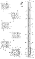
- a linear drive 1 comprises a rotatably driven threaded spindle 2 which is arranged within a profile 3 which is essentially U-shaped in cross section.
- a carriage 4 is movably mounted on the threaded spindle 2 and is held on a rotationally fixed spindle nut 5.
- the threaded spindle 2 can be used for a ball screw drive or have another thread, for example a trapezoidal thread.
- a rail 6 is fixed, which serves to guide the spindle nut 5.
- the profile 3 is closed at the end with a first bearing 7 and on the opposite side via a second bearing 9 for the threaded spindle 2.
- a pin 8 of the threaded spindle 2 protrudes, which can be coupled to a drive (not shown) in order to drive the threaded spindle 2.
- the linear drive 1 can be produced in a longer length of, for example, 2 m to 10 m, the threaded spindle 2 being supported depending on the length.
- a plurality of support elements 10, 11, 12, 13 and 14 are provided around the threaded spindle 2, which are each guided on the rail 6.
- the support elements 10, 11, 12, 13, 14 are each positioned at predetermined intermediate positions on the profile 3 in order to support the threaded spindle 2 against movement perpendicular to the longitudinal direction at certain intervals.
- the rail 6 has a higher strength than the profile 3, which can be produced as an extruded aluminum profile.
- the rail 6 can be designed as a steel profile which has an essentially rectangular cross section with a widened head section 36, a narrower middle section 37 and a widened foot section 38.
- the foot section 38 is fixed to the profile 3.
- the profile 3 is essentially U-shaped in cross section and has two legs 30, within which the threaded spindle 2 is arranged.
- the legs 30 are connected to one another via a bottom-side section 31 to which the rail 6 is fixed.
- the spindle nut 5 and the support elements 10 to 14 can encompass the head section 36 in a U-shaped manner, so that lifting of the support elements 10 to 14 and the spindle nut 5 is prevented and a guide is provided that only moves in the longitudinal direction of the rail 6.
- the support element 10 thus has a stop 17 which interacts with a stopper 16 which is mounted on a leg 30 of the profile 3.
- the support element 11 has a stop 18 and the support element 12 has a stop 19 which are arranged at different positions so that each support element 10, 11, 12, 13, 14 interacts with a predetermined stop on the profile 3.
- the support element 13 has a stop 23 which cooperates with a stopper 20 which is fixed to the profile 3.
- a stop 22 is provided on the support element 14, which interacts with a stopper 21.
- the spindle nut 5 moves with the slide 4 to the left. Then the support elements 10 to 14 are collected on the spindle nut 5 and the slide 4, respectively, while the support elements 10 ', 11', 12 ', 13' and 14 'are stopped at predetermined stoppers on the profile 3, and then the threaded spindle 2 support.
- the support elements 10 to 14 on the one hand and 10 'to 14' on the other hand are held together by magnetic forces, the holding forces of the magnets being remove the spindle nut 5.
- the outer support elements 14 and 14 ' are thus easier to detach from the adjacent support elements 13 and 13' than the support elements 13 and 13 'from the support elements 12 and 12' located further inside. This prevents a plurality of support elements 10 to 14 and 10 'to 14' from being accidentally stopped on a stopper.
- a slide 4 is fixed, which has a platform 15 on which any components can be fixed that are to be moved via the linear drive 1.
- both the spindle nut 5 and the support elements 10 to 14 embrace the upper head portion 36 of the rail 6 in a U-shape.
- the rail 6 has a cross section of a similar size to the threaded spindle 2, so that a stable support of the support elements 10 to 14 on the rail 6 is ensured.
- the rail 6 can be fixed to the bottom section 31 of the profile 3 by means of screw connections or other fastening means.
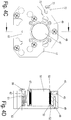
- FIG. 3 a support element 10 is shown in detail, the other support elements 11 to 14 and 10 'to 14' being constructed similarly, only the position of the respective stop 17 varies.
- the number of magnets 45 on the support elements 11 to 14 or 10 'to 14' is different.
- the support element 10 comprises a central support body 40, in which a circular passage for the threaded spindle 2 is recessed.
- the support body 40 comprises a U-shaped receptacle 42 which can be pushed onto the widened head section 36 of the rail 6.
- On the U-shaped receptacle 42 inwardly directed webs are formed with guide surfaces 43 which engage behind the widened head section 36.
- a plurality of recesses 44 are also formed in the support body 40, each of which serves to receive a magnet 45.
- the number of magnets 45 which are inserted into the recesses 44 determines the holding forces between the support element 10 and an adjacent support element 11.
- the support elements, which are arranged closer to the spindle nut 5, have more magnets 45 than support elements located further out, so that the holding forces between two support elements decrease away from the spindle nut.
- the recesses 44 of the support body 40 are closed by a plate 46 which is permeable to the magnetic forces, for example made of aluminum exists, and prevents the magnets 45 from falling out.
- the plate 46 also has a bushing 47 for the threaded spindle 2, the plate 46 being fixed to the support body 40 by means of a plurality of screws 48.
- a further plate 49 is provided, which is fixed by screws 48 to the support body 40.
- the plate 49 is made of metal and can be fixed to magnets of an adjacent support element or the spindle nut 5 by magnetic forces.
- a bushing 50 is inserted in the feedthrough 41, which is slotted and is pressed against the outer circumference of the threaded spindle 2 with a prestress.
- elastic O-rings 53 are provided around the bushing 50, which bear against the outer circumference of the passage 41 of the support body 40 and elastically prestress the bushing 50 against the threaded spindle 2 on the inside.
- the bushing 50 has a radially projecting collar 52, which is arranged between the plate 49 and an end face of the support body 40, so that the bushing 50 cannot slip in the axial direction.
- An elastic sealant may be injected adjacent to the O-rings 53 in order to further improve the damping, which leads to less vibrations on the threaded spindle 2 and less noise.
- a clamping mechanism 60 which has a clamping element 61 which comprises a bevel 62 inclined to the longitudinal direction of the rail 6.
- the clamping element 61 is biased in the longitudinal direction by a spring 63.
- the spring 63 is supported between the plate 49 and an end face 64 on the driver element 61.
- a screw 66 is screwed into a threaded bore 65 on the clamping element 61, which protrudes beyond the plate 46, the overhang being adjustable.
- the support member 10 is shown in an assembled position.
- the clamping mechanism 60 is arranged above the receptacle 42 for receiving the head section 36 of the rail 6.
- the screw 66 protrudes in the longitudinal direction of the rail 6 over the plate 46 and can be pressed in in the longitudinal direction against the force of the spring 63.
- the screw 66 also serves to set the depth for the clamping element 61.
- the run-on slope 62 of the clamping element 61 interacts with a slope 67 of the support body 40, the clamping element 61 being pressed against the slope 67 by the force of the spring 63, so that the clamping element 61 is pressed downward against the rail 6 by the force of the spring 63 is pressed. As a result, the support element 10 can be clamped on the rail 6.
- the clamping mechanism 60 is unlocked.
- the spindle nut 5 or the slide 4 is moved to the support element 10, a stop surface first striking the screw 66 before there is contact between the plate 46 and the slide 4 or the spindle nut 5.
- the screw 66 is pressed in against the force of the spring 63 and thus moves the clamping element 61 in the direction of the plate 49.
- the clamping forces acting on the rail 6 are canceled, since the clamping element 61 is no longer opposed by the run-up slope 62 and the slope 67 the rail 6 is biased.
- the holding forces applied by the magnets 45 to the spindle nut 5 or the slide 4 or to an adjacent support element 11 to 14 are greater than the force of the spring 63, so that an inadvertent release from the coupled position is prevented by the spring 63.
- the support element 10 After unlocking the clamping mechanism 60, the support element 10 can be moved smoothly along the rail 6, the support body 40 providing guidance along the rail 6 and the clamping mechanism 60 being disengaged. If the support element 10 is now stopped on the stopper 16 on the profile 3 and the spindle nut 5 with the slide 4 moves away from the support element 10, the screw 66 is released and the clamping mechanism 60 is activated by the pressure of the spring 63 and clamps through the bevel 67 and the bevel 62 the clamping element 61 again against the rail 6.
- the other support elements 11 to 14 are constructed like the support element 10, except for the position of the stop 17 and the number of magnets 45. For the rest, reference is made to the above statements with regard to the design of the support elements 11 to 14 and 10 'to 14'.
- a stopper 70 is also shown, which can be fixed on a groove of the profile 3.
- the stopper 70 comprises two sliding blocks 71 which can be inserted into a corresponding groove on the legs 30 of the profile 3.
- the sliding blocks 71 are connected via screws 74 to a strip 72 which comprises a projecting leg 73 which serves as a stop surface. Openings 75 are provided in the strip 72 for the passage of the screws 74, so that the strip 72 can be fixed at the desired intermediate position of the profile 3 via the screws 74.
- the stopper 70 is fixed to the profile 3 and defines a stop position for one of the support elements 10 to 14 or 10 'to 14'.
- a stopper 70 it is of course also possible for a stopper 70 to define a stop for two support elements 10 to 14 or 10 'to 14', for support elements which are located on opposite sides of the spindle nut 5. Distributed over the length of the profile 3 are a large number of such stoppers 70, each of which defines a stop for one of the support elements 10 to 14 or 10 'to 14'. The stoppers 70 fixed to the profile 3 must not interfere with one another, which is why a stop surface of the stopper 70 is arranged at different positions in a cross-sectional view.
- the plate 49 of the support element 10 has the stop 17, while the plate 49' the stop 17 'and the Plate 49 "has the stop 17".
- the profile 3 is U-shaped in cross section. It is of course possible to manufacture the linear drive 1 with a profile 3 with a different cross section.
- the cross section of the rail 6 can also be varied in order to enable stable linear guidance of the spindle nut 5 and the support elements 10 to 14 and 10 'to 14'.
- the guidance of the support elements 10 to 14 and 10 'to 14' and the spindle nut 5 can be designed as a sliding guide, but rolling elements can also be provided in order to make the guidance even more smooth.
- the support elements 10 to 14 and 10 'to 14' can also be equipped with damping means to avoid loud impact noises.
- the support elements 10 to 14 and 10 'to 14' can meet at a higher speed, so that elastic elements, for example rubber dampers or other elastic components, can be provided on the contact surfaces in order to reduce the noise.
- at least one of the plates 46 and / or 49 can be provided with an elastic coating.
Landscapes
- Engineering & Computer Science (AREA)
- General Engineering & Computer Science (AREA)
- Mechanical Engineering (AREA)
- Transmission Devices (AREA)
Claims (11)
- Entraînement linéaire (1) comprenant :a) une broche filetée (2) entraînée en rotation ;b) un écrou de broche (5) guidé de manière bloquée en rotation qui peut être déplacé dans une direction longitudinale par la broche filetée (2) ;c) un profilé (3) s'étendant dans la direction longitudinale ;d) au moins un élément de support (10-14 ; 10'-14') pour supporter la broche filetée (2) contre un mouvement perpendiculaire à la direction longitudinale, ledit au moins un élément de support (10-14 ; 10-14') présentant un logement (42) qui enserre en forme de U un rail (6) fixé au profilé (3),caractérisé en ce que ledit au moins un élément de support (10-14 ; 10'-14') présente un mécanisme de serrage (60) au moyen duquel l'élément de support (10-14 ; 10'-14') peut être fixé par force et le mécanisme de serrage (60) est déverrouillé lors de l'accouplement de deux éléments de support voisins (10-14 ; 10'-14') ou avec l'écrou de broche (2) et le mécanisme de serrage (60) est activé lors de la libération de l'accouplement de l'élément de support (10-14 ; 10'-14') de l'élément de support voisin (10-14 ; 10'-14') ou de l'écrou de broche (5).
- Entraînement linéaire selon la revendication 1, caractérisé en ce que le mécanisme de serrage (60) serre par force l'élément de support (10-14 ; 10'-14') sur le profilé (3) ou sur un élément (6) fixé au profilé (3).
- Entraînement linéaire selon la revendication 1 ou 2, caractérisé en ce que le mécanisme de serrage (60) comprend un élément de serrage mobile (61) qui est précontraint dans une position de serrage par un ressort (63).
- Entraînement linéaire selon la revendication 3, caractérisé en ce que l'élément de serrage (61) présente une rampe (62) qui est appuyée sur l'élément de support (10-14 ; 10'-14') et précontraint l'élément de serrage (61) dans une direction perpendiculaire à la direction longitudinale de la broche filetée (2).
- Entraînement linéaire selon l'une des revendications précédentes, caractérisé en ce que l'élément de support (10-14 ; 10'-14') peut être serré sur un rail (6) fixé au profilé (3) par le mécanisme de serrage (60).
- Entraînement linéaire selon la revendication 5, caractérisé en ce que le rail (6) est réalisé sous la forme d'un rail en acier.
- Entraînement linéaire selon l'une des revendications précédentes, caractérisé en ce que plusieurs éléments de support (10-14 ; 10'-14') sont prévus des deux côtés de l'écrou de broche (5), lesquels peuvent être accouplés à l'écrou de broche (5) ou à un élément de support (10-14 ; 10'-14') fixé à l'écrou de broche (5) et peuvent être désaccouplés dans une position prédéterminée de l'écrou de broche (5) ou d'un élément de support (10-14 ; 10'-14') fixé à l'écrou de broche (5) pour supporter la broche filetée (2).
- Entraînement linéaire selon l'une des revendications précédentes, caractérisé en ce que chaque élément de support (10-14 ; 10'-14') présente une butée (17, 18, 19, 22) qui coopère avec un arrêt (16, 20, 21, 70) prévu sur le profilé (3) pour fixer l'élément de support (10-14 ; 10'-14') dans une position prédéterminée dans la direction longitudinale de la broche filetée (2) sur le rail (6) ou le profilé (3).
- Entraînement linéaire selon l'une des revendications précédentes, caractérisé en ce que le mécanisme de serrage (60) est disposé au voisinage du logement (42) et un élément de serrage (61) peut être serré contre le rail (6).
- Entraînement linéaire selon l'une des revendications précédentes, caractérisé en ce que ledit au moins un élément de support (10-14 ; 10'-14') présente un corps de support central (40), sur chacun des côtés opposés duquel est fixée une plaque (46, 49).
- Entraînement linéaire selon la revendication 10, caractérisé en ce qu'une butée (17, 17', 17") est réalisée d'un seul tenant avec une plaque (49, 49', 49").
Applications Claiming Priority (1)
| Application Number | Priority Date | Filing Date | Title |
|---|---|---|---|
| DE202012102315U DE202012102315U1 (de) | 2012-06-22 | 2012-06-22 | Linearantrieb |
Publications (2)
| Publication Number | Publication Date |
|---|---|
| EP2677201A1 EP2677201A1 (fr) | 2013-12-25 |
| EP2677201B1 true EP2677201B1 (fr) | 2019-12-18 |
Family
ID=48607110
Family Applications (1)
| Application Number | Title | Priority Date | Filing Date |
|---|---|---|---|
| EP13171031.1A Active EP2677201B1 (fr) | 2012-06-22 | 2013-06-07 | Entraînement linéaire |
Country Status (2)
| Country | Link |
|---|---|
| EP (1) | EP2677201B1 (fr) |
| DE (1) | DE202012102315U1 (fr) |
Cited By (2)
| Publication number | Priority date | Publication date | Assignee | Title |
|---|---|---|---|---|
| DE102020212408A1 (de) | 2020-09-30 | 2022-03-31 | Wolfgang Rixen | Linearantrieb |
| DE102020212409A1 (de) | 2020-09-30 | 2022-03-31 | Wolfgang Rixen | Linearantrieb |
Families Citing this family (1)
| Publication number | Priority date | Publication date | Assignee | Title |
|---|---|---|---|---|
| CN116557419A (zh) * | 2023-05-12 | 2023-08-08 | 芜湖熠康智能科技有限公司 | 直线模组 |
Family Cites Families (6)
| Publication number | Priority date | Publication date | Assignee | Title |
|---|---|---|---|---|
| DE77001C (de) * | C. gronert in Berlin N.W., Luisenstrafse 22a | Vorrichtung zur Lagerung und Führung langer Schraubenspindeln, Wellen u. dergl | ||
| DE3804117A1 (de) | 1988-02-11 | 1989-08-24 | Neff Gewindespindeln | Mechanische lineareinheit |
| DE19636272A1 (de) * | 1996-09-06 | 1998-03-12 | Star Gmbh | Linearführungseinrichtung |
| DE10002849C2 (de) * | 2000-01-24 | 2002-03-28 | Rexroth Star Gmbh | Lineareinheit |
| DE102008012842B4 (de) * | 2008-03-06 | 2014-12-04 | Rk Rose + Krieger Gmbh Verbindungs- Und Positioniersysteme | Spindelantrieb |
| SI2584223T1 (sl) * | 2011-10-17 | 2015-06-30 | Ntn-Snr Roulements | Navojno pogonsko vreteno, ki vsebuje drsne leĺ˝aje in drsni leĺ˝aj |
-
2012
- 2012-06-22 DE DE202012102315U patent/DE202012102315U1/de not_active Expired - Lifetime
-
2013
- 2013-06-07 EP EP13171031.1A patent/EP2677201B1/fr active Active
Non-Patent Citations (1)
| Title |
|---|
| None * |
Cited By (2)
| Publication number | Priority date | Publication date | Assignee | Title |
|---|---|---|---|---|
| DE102020212408A1 (de) | 2020-09-30 | 2022-03-31 | Wolfgang Rixen | Linearantrieb |
| DE102020212409A1 (de) | 2020-09-30 | 2022-03-31 | Wolfgang Rixen | Linearantrieb |
Also Published As
| Publication number | Publication date |
|---|---|
| EP2677201A1 (fr) | 2013-12-25 |
| DE202012102315U1 (de) | 2013-09-25 |
Similar Documents
| Publication | Publication Date | Title |
|---|---|---|
| EP2677200B1 (fr) | Entraînement linéaire | |
| EP1197319B1 (fr) | Entraînement par coin | |
| EP2405786A2 (fr) | Glissière de tiroir | |
| EP1114232B1 (fr) | Dispositif pour guider un element de porte coulissante et en limiter la course | |
| EP2668869B1 (fr) | Elément de verrouillage amovible | |
| DE4119610A1 (de) | Spindelantrieb fuer eine verstelleinrichtung fuer fahrzeugsitze | |
| EP2677201B1 (fr) | Entraînement linéaire | |
| DE202008015848U1 (de) | Synchronführung eines Schubelementes | |
| EP3859110B1 (fr) | Ferrure de porte coulissante et procédé de déplacement d'un dispositif de commande | |
| EP2677202B1 (fr) | Entraînement linéaire | |
| WO2018082728A1 (fr) | Support de barre omnibus et ensemble correspondant | |
| EP3113892B1 (fr) | Coulisseau porte-outil | |
| DE19914860A1 (de) | Einrichtung zur Führung und Wegbegrenzung eines Schiebetürelements | |
| DE102011003671A1 (de) | Schalungsträger und Schalungsanordnung | |
| DE202016106504U1 (de) | Montagewerkzeug für die Montage einer Schaltschranktür an einem Schaltschrankgehäuse und eine entsprechende Schaltschrankanordnung | |
| EP3569804B1 (fr) | Dispositif de guidage pour une porte coulissante | |
| EP2853670B1 (fr) | Rail de roulement pour une porte coulissante | |
| DE10004178A1 (de) | Bolzenführungseinrichtung für eine Schwimmsattel-Scheibenbremse | |
| WO2015078765A1 (fr) | Organe d'écartement pour dispositif de guidage par glissement et colonne de levage | |
| EP1612436B1 (fr) | Guide linéaire avec rail profilé | |
| DE10035956C2 (de) | Laufschienen-Klemmhalter für die Befestigung von Laufschienen für Schiebetürsysteme | |
| DE102018100550A1 (de) | Führungsgleiter für ein schiebetür- und/oder schiebefenstersystem, beweglicher schieberahmen mit einem führungsgleiter sowie schiebetür- und/oder schiebefenstersystem mit führungsleiter | |
| DE8704039U1 (de) | Lagervorrichtung, insbesondere zur Lagerung eines Wickelrohrs für einen Rolladen- o. dgl. -antrieb | |
| DE212019000344U1 (de) | Abstandshalter zur Einstellung eines Sollabstandes zwischen zwei Komponenten | |
| EP4003653B1 (fr) | Outil de vissage permettant le vissage d'une vis longue |
Legal Events
| Date | Code | Title | Description |
|---|---|---|---|
| PUAI | Public reference made under article 153(3) epc to a published international application that has entered the european phase |
Free format text: ORIGINAL CODE: 0009012 |
|
| AK | Designated contracting states |
Kind code of ref document: A1 Designated state(s): AL AT BE BG CH CY CZ DE DK EE ES FI FR GB GR HR HU IE IS IT LI LT LU LV MC MK MT NL NO PL PT RO RS SE SI SK SM TR |
|
| AX | Request for extension of the european patent |
Extension state: BA ME |
|
| 17P | Request for examination filed |
Effective date: 20140221 |
|
| RBV | Designated contracting states (corrected) |
Designated state(s): AL AT BE BG CH CY CZ DE DK EE ES FI FR GB GR HR HU IE IS IT LI LT LU LV MC MK MT NL NO PL PT RO RS SE SI SK SM TR |
|
| STAA | Information on the status of an ep patent application or granted ep patent |
Free format text: STATUS: EXAMINATION IS IN PROGRESS |
|
| 17Q | First examination report despatched |
Effective date: 20181206 |
|
| GRAP | Despatch of communication of intention to grant a patent |
Free format text: ORIGINAL CODE: EPIDOSNIGR1 |
|
| STAA | Information on the status of an ep patent application or granted ep patent |
Free format text: STATUS: GRANT OF PATENT IS INTENDED |
|
| INTG | Intention to grant announced |
Effective date: 20190819 |
|
| GRAS | Grant fee paid |
Free format text: ORIGINAL CODE: EPIDOSNIGR3 |
|
| GRAA | (expected) grant |
Free format text: ORIGINAL CODE: 0009210 |
|
| STAA | Information on the status of an ep patent application or granted ep patent |
Free format text: STATUS: THE PATENT HAS BEEN GRANTED |
|
| AK | Designated contracting states |
Kind code of ref document: B1 Designated state(s): AL AT BE BG CH CY CZ DE DK EE ES FI FR GB GR HR HU IE IS IT LI LT LU LV MC MK MT NL NO PL PT RO RS SE SI SK SM TR |
|
| REG | Reference to a national code |
Ref country code: GB Ref legal event code: FG4D Free format text: NOT ENGLISH |
|
| REG | Reference to a national code |
Ref country code: CH Ref legal event code: EP |
|
| REG | Reference to a national code |
Ref country code: DE Ref legal event code: R096 Ref document number: 502013014070 Country of ref document: DE |
|
| REG | Reference to a national code |
Ref country code: IE Ref legal event code: FG4D Free format text: LANGUAGE OF EP DOCUMENT: GERMAN |
|
| REG | Reference to a national code |
Ref country code: AT Ref legal event code: REF Ref document number: 1214960 Country of ref document: AT Kind code of ref document: T Effective date: 20200115 |
|
| REG | Reference to a national code |
Ref country code: NL Ref legal event code: MP Effective date: 20191218 |
|
| PG25 | Lapsed in a contracting state [announced via postgrant information from national office to epo] |
Ref country code: FI Free format text: LAPSE BECAUSE OF FAILURE TO SUBMIT A TRANSLATION OF THE DESCRIPTION OR TO PAY THE FEE WITHIN THE PRESCRIBED TIME-LIMIT Effective date: 20191218 Ref country code: BG Free format text: LAPSE BECAUSE OF FAILURE TO SUBMIT A TRANSLATION OF THE DESCRIPTION OR TO PAY THE FEE WITHIN THE PRESCRIBED TIME-LIMIT Effective date: 20200318 Ref country code: NO Free format text: LAPSE BECAUSE OF FAILURE TO SUBMIT A TRANSLATION OF THE DESCRIPTION OR TO PAY THE FEE WITHIN THE PRESCRIBED TIME-LIMIT Effective date: 20200318 Ref country code: SE Free format text: LAPSE BECAUSE OF FAILURE TO SUBMIT A TRANSLATION OF THE DESCRIPTION OR TO PAY THE FEE WITHIN THE PRESCRIBED TIME-LIMIT Effective date: 20191218 Ref country code: LV Free format text: LAPSE BECAUSE OF FAILURE TO SUBMIT A TRANSLATION OF THE DESCRIPTION OR TO PAY THE FEE WITHIN THE PRESCRIBED TIME-LIMIT Effective date: 20191218 Ref country code: GR Free format text: LAPSE BECAUSE OF FAILURE TO SUBMIT A TRANSLATION OF THE DESCRIPTION OR TO PAY THE FEE WITHIN THE PRESCRIBED TIME-LIMIT Effective date: 20200319 Ref country code: LT Free format text: LAPSE BECAUSE OF FAILURE TO SUBMIT A TRANSLATION OF THE DESCRIPTION OR TO PAY THE FEE WITHIN THE PRESCRIBED TIME-LIMIT Effective date: 20191218 |
|
| REG | Reference to a national code |
Ref country code: LT Ref legal event code: MG4D |
|
| PG25 | Lapsed in a contracting state [announced via postgrant information from national office to epo] |
Ref country code: HR Free format text: LAPSE BECAUSE OF FAILURE TO SUBMIT A TRANSLATION OF THE DESCRIPTION OR TO PAY THE FEE WITHIN THE PRESCRIBED TIME-LIMIT Effective date: 20191218 Ref country code: RS Free format text: LAPSE BECAUSE OF FAILURE TO SUBMIT A TRANSLATION OF THE DESCRIPTION OR TO PAY THE FEE WITHIN THE PRESCRIBED TIME-LIMIT Effective date: 20191218 |
|
| PG25 | Lapsed in a contracting state [announced via postgrant information from national office to epo] |
Ref country code: AL Free format text: LAPSE BECAUSE OF FAILURE TO SUBMIT A TRANSLATION OF THE DESCRIPTION OR TO PAY THE FEE WITHIN THE PRESCRIBED TIME-LIMIT Effective date: 20191218 |
|
| PG25 | Lapsed in a contracting state [announced via postgrant information from national office to epo] |
Ref country code: EE Free format text: LAPSE BECAUSE OF FAILURE TO SUBMIT A TRANSLATION OF THE DESCRIPTION OR TO PAY THE FEE WITHIN THE PRESCRIBED TIME-LIMIT Effective date: 20191218 Ref country code: PT Free format text: LAPSE BECAUSE OF FAILURE TO SUBMIT A TRANSLATION OF THE DESCRIPTION OR TO PAY THE FEE WITHIN THE PRESCRIBED TIME-LIMIT Effective date: 20200513 Ref country code: RO Free format text: LAPSE BECAUSE OF FAILURE TO SUBMIT A TRANSLATION OF THE DESCRIPTION OR TO PAY THE FEE WITHIN THE PRESCRIBED TIME-LIMIT Effective date: 20191218 Ref country code: CZ Free format text: LAPSE BECAUSE OF FAILURE TO SUBMIT A TRANSLATION OF THE DESCRIPTION OR TO PAY THE FEE WITHIN THE PRESCRIBED TIME-LIMIT Effective date: 20191218 Ref country code: NL Free format text: LAPSE BECAUSE OF FAILURE TO SUBMIT A TRANSLATION OF THE DESCRIPTION OR TO PAY THE FEE WITHIN THE PRESCRIBED TIME-LIMIT Effective date: 20191218 |
|
| PG25 | Lapsed in a contracting state [announced via postgrant information from national office to epo] |
Ref country code: SK Free format text: LAPSE BECAUSE OF FAILURE TO SUBMIT A TRANSLATION OF THE DESCRIPTION OR TO PAY THE FEE WITHIN THE PRESCRIBED TIME-LIMIT Effective date: 20191218 Ref country code: IS Free format text: LAPSE BECAUSE OF FAILURE TO SUBMIT A TRANSLATION OF THE DESCRIPTION OR TO PAY THE FEE WITHIN THE PRESCRIBED TIME-LIMIT Effective date: 20200418 Ref country code: SM Free format text: LAPSE BECAUSE OF FAILURE TO SUBMIT A TRANSLATION OF THE DESCRIPTION OR TO PAY THE FEE WITHIN THE PRESCRIBED TIME-LIMIT Effective date: 20191218 |
|
| REG | Reference to a national code |
Ref country code: DE Ref legal event code: R097 Ref document number: 502013014070 Country of ref document: DE |
|
| PLBE | No opposition filed within time limit |
Free format text: ORIGINAL CODE: 0009261 |
|
| STAA | Information on the status of an ep patent application or granted ep patent |
Free format text: STATUS: NO OPPOSITION FILED WITHIN TIME LIMIT |
|
| PG25 | Lapsed in a contracting state [announced via postgrant information from national office to epo] |
Ref country code: DK Free format text: LAPSE BECAUSE OF FAILURE TO SUBMIT A TRANSLATION OF THE DESCRIPTION OR TO PAY THE FEE WITHIN THE PRESCRIBED TIME-LIMIT Effective date: 20191218 Ref country code: ES Free format text: LAPSE BECAUSE OF FAILURE TO SUBMIT A TRANSLATION OF THE DESCRIPTION OR TO PAY THE FEE WITHIN THE PRESCRIBED TIME-LIMIT Effective date: 20191218 |
|
| 26N | No opposition filed |
Effective date: 20200921 |
|
| PG25 | Lapsed in a contracting state [announced via postgrant information from national office to epo] |
Ref country code: SI Free format text: LAPSE BECAUSE OF FAILURE TO SUBMIT A TRANSLATION OF THE DESCRIPTION OR TO PAY THE FEE WITHIN THE PRESCRIBED TIME-LIMIT Effective date: 20191218 |
|
| PG25 | Lapsed in a contracting state [announced via postgrant information from national office to epo] |
Ref country code: MC Free format text: LAPSE BECAUSE OF FAILURE TO SUBMIT A TRANSLATION OF THE DESCRIPTION OR TO PAY THE FEE WITHIN THE PRESCRIBED TIME-LIMIT Effective date: 20191218 |
|
| REG | Reference to a national code |
Ref country code: CH Ref legal event code: PL |
|
| PG25 | Lapsed in a contracting state [announced via postgrant information from national office to epo] |
Ref country code: PL Free format text: LAPSE BECAUSE OF FAILURE TO SUBMIT A TRANSLATION OF THE DESCRIPTION OR TO PAY THE FEE WITHIN THE PRESCRIBED TIME-LIMIT Effective date: 20191218 |
|
| GBPC | Gb: european patent ceased through non-payment of renewal fee |
Effective date: 20200607 |
|
| PG25 | Lapsed in a contracting state [announced via postgrant information from national office to epo] |
Ref country code: LU Free format text: LAPSE BECAUSE OF NON-PAYMENT OF DUE FEES Effective date: 20200607 |
|
| REG | Reference to a national code |
Ref country code: BE Ref legal event code: MM Effective date: 20200630 |
|
| PG25 | Lapsed in a contracting state [announced via postgrant information from national office to epo] |
Ref country code: GB Free format text: LAPSE BECAUSE OF NON-PAYMENT OF DUE FEES Effective date: 20200607 Ref country code: CH Free format text: LAPSE BECAUSE OF NON-PAYMENT OF DUE FEES Effective date: 20200630 Ref country code: IE Free format text: LAPSE BECAUSE OF NON-PAYMENT OF DUE FEES Effective date: 20200607 Ref country code: LI Free format text: LAPSE BECAUSE OF NON-PAYMENT OF DUE FEES Effective date: 20200630 |
|
| PG25 | Lapsed in a contracting state [announced via postgrant information from national office to epo] |
Ref country code: BE Free format text: LAPSE BECAUSE OF NON-PAYMENT OF DUE FEES Effective date: 20200630 |
|
| REG | Reference to a national code |
Ref country code: AT Ref legal event code: MM01 Ref document number: 1214960 Country of ref document: AT Kind code of ref document: T Effective date: 20200607 |
|
| PG25 | Lapsed in a contracting state [announced via postgrant information from national office to epo] |
Ref country code: AT Free format text: LAPSE BECAUSE OF NON-PAYMENT OF DUE FEES Effective date: 20200607 |
|
| PG25 | Lapsed in a contracting state [announced via postgrant information from national office to epo] |
Ref country code: TR Free format text: LAPSE BECAUSE OF FAILURE TO SUBMIT A TRANSLATION OF THE DESCRIPTION OR TO PAY THE FEE WITHIN THE PRESCRIBED TIME-LIMIT Effective date: 20191218 Ref country code: MT Free format text: LAPSE BECAUSE OF FAILURE TO SUBMIT A TRANSLATION OF THE DESCRIPTION OR TO PAY THE FEE WITHIN THE PRESCRIBED TIME-LIMIT Effective date: 20191218 Ref country code: CY Free format text: LAPSE BECAUSE OF FAILURE TO SUBMIT A TRANSLATION OF THE DESCRIPTION OR TO PAY THE FEE WITHIN THE PRESCRIBED TIME-LIMIT Effective date: 20191218 |
|
| PG25 | Lapsed in a contracting state [announced via postgrant information from national office to epo] |
Ref country code: MK Free format text: LAPSE BECAUSE OF FAILURE TO SUBMIT A TRANSLATION OF THE DESCRIPTION OR TO PAY THE FEE WITHIN THE PRESCRIBED TIME-LIMIT Effective date: 20191218 |
|
| P01 | Opt-out of the competence of the unified patent court (upc) registered |
Effective date: 20230419 |
|
| PGFP | Annual fee paid to national office [announced via postgrant information from national office to epo] |
Ref country code: DE Payment date: 20250627 Year of fee payment: 13 |
|
| PGFP | Annual fee paid to national office [announced via postgrant information from national office to epo] |
Ref country code: FR Payment date: 20250612 Year of fee payment: 13 |
|
| PGFP | Annual fee paid to national office [announced via postgrant information from national office to epo] |
Ref country code: IT Payment date: 20250630 Year of fee payment: 13 |