EP2677381A1 - Procédé destiné au fonctionnement d`un système dýautomatisation - Google Patents
Procédé destiné au fonctionnement d`un système dýautomatisation Download PDFInfo
- Publication number
- EP2677381A1 EP2677381A1 EP12172971.9A EP12172971A EP2677381A1 EP 2677381 A1 EP2677381 A1 EP 2677381A1 EP 12172971 A EP12172971 A EP 12172971A EP 2677381 A1 EP2677381 A1 EP 2677381A1
- Authority
- EP
- European Patent Office
- Prior art keywords
- automation
- automation system
- devices
- subtasks
- tasks
- Prior art date
- Legal status (The legal status is an assumption and is not a legal conclusion. Google has not performed a legal analysis and makes no representation as to the accuracy of the status listed.)
- Withdrawn
Links
Images

Classifications
-
- G—PHYSICS
- G05—CONTROLLING; REGULATING
- G05B—CONTROL OR REGULATING SYSTEMS IN GENERAL; FUNCTIONAL ELEMENTS OF SUCH SYSTEMS; MONITORING OR TESTING ARRANGEMENTS FOR SUCH SYSTEMS OR ELEMENTS
- G05B19/00—Program-control systems
- G05B19/02—Program-control systems electric
- G05B19/18—Numerical control [NC], i.e. automatically operating machines, in particular machine tools, e.g. in a manufacturing environment, so as to execute positioning, movement or co-ordinated operations by means of program data in numerical form
- G05B19/414—Structure of the control system, e.g. common controller or multiprocessor systems, interface to servo, programmable interface controller
- G05B19/4148—Structure of the control system, e.g. common controller or multiprocessor systems, interface to servo, programmable interface controller characterised by using several processors for different functions, distributed (real-time) systems
-
- G—PHYSICS
- G05—CONTROLLING; REGULATING
- G05B—CONTROL OR REGULATING SYSTEMS IN GENERAL; FUNCTIONAL ELEMENTS OF SUCH SYSTEMS; MONITORING OR TESTING ARRANGEMENTS FOR SUCH SYSTEMS OR ELEMENTS
- G05B19/00—Program-control systems
- G05B19/02—Program-control systems electric
- G05B19/418—Total factory control, i.e. centrally controlling a plurality of machines, e.g. direct or distributed numerical control [DNC], flexible manufacturing systems [FMS], integrated manufacturing systems [IMS] or computer integrated manufacturing [CIM]
- G05B19/41845—Total factory control, i.e. centrally controlling a plurality of machines, e.g. direct or distributed numerical control [DNC], flexible manufacturing systems [FMS], integrated manufacturing systems [IMS] or computer integrated manufacturing [CIM] characterised by system universality, reconfigurability, modularity
-
- G—PHYSICS
- G05—CONTROLLING; REGULATING
- G05B—CONTROL OR REGULATING SYSTEMS IN GENERAL; FUNCTIONAL ELEMENTS OF SUCH SYSTEMS; MONITORING OR TESTING ARRANGEMENTS FOR SUCH SYSTEMS OR ELEMENTS
- G05B2219/00—Program-control systems
- G05B2219/20—Pc systems
- G05B2219/25—Pc structure of the system
- G05B2219/25231—Command, task has deadline, time limit to be executed
-
- G—PHYSICS
- G05—CONTROLLING; REGULATING
- G05B—CONTROL OR REGULATING SYSTEMS IN GENERAL; FUNCTIONAL ELEMENTS OF SUCH SYSTEMS; MONITORING OR TESTING ARRANGEMENTS FOR SUCH SYSTEMS OR ELEMENTS
- G05B2219/00—Program-control systems
- G05B2219/20—Pc systems
- G05B2219/25—Pc structure of the system
- G05B2219/25232—DCS, distributed control system, decentralised control unit
-
- Y—GENERAL TAGGING OF NEW TECHNOLOGICAL DEVELOPMENTS; GENERAL TAGGING OF CROSS-SECTIONAL TECHNOLOGIES SPANNING OVER SEVERAL SECTIONS OF THE IPC; TECHNICAL SUBJECTS COVERED BY FORMER USPC CROSS-REFERENCE ART COLLECTIONS [XRACs] AND DIGESTS
- Y02—TECHNOLOGIES OR APPLICATIONS FOR MITIGATION OR ADAPTATION AGAINST CLIMATE CHANGE
- Y02P—CLIMATE CHANGE MITIGATION TECHNOLOGIES IN THE PRODUCTION OR PROCESSING OF GOODS
- Y02P90/00—Enabling technologies with a potential contribution to greenhouse gas [GHG] emissions mitigation
- Y02P90/02—Total factory control, e.g. smart factories, flexible manufacturing systems [FMS] or integrated manufacturing systems [IMS]
Definitions
- the present invention relates to a method for operating an automation system. Moreover, the present invention relates to an automation system.
- Automation systems comprise a plurality of automation devices, which can essentially be divided into two groups.
- the automation system comprises computing devices which have a processor or a CPU and can perform corresponding calculations.
- automation systems usually include peripheral devices which, as input / output modules, represent a physical connection between the technical process to be automated and the automated technical system. The peripheral devices forward the measured with the corresponding sensors physical quantities, such as the pressure, temperature or position of the technical process as analog or digital data in the form of communication messages via field buses to the computing devices that make the actual processing of the data.
- peripheral devices The organization and thus the assignment of the peripheral devices to the computing devices is strictly hierarchical, so that there is an N: 1 relationship between the peripheral devices and the computing devices.
- Each peripheral device is connected to a specific computing device, so that only these can process the data of the peripheral device.
- the communication takes place via bus systems at this field level, which are therefore also referred to as fieldbus.
- the communication of the computing devices with each other as well as the communication with input devices or maintenance devices takes place with the aid of another bus system on the automation level.
- the division into two bus systems has grown historically not least due to the different requirements of the bus systems at the field and automation level. These requirements include, among other things, a deterministic time response during data transmission in order to be able to estimate the data not only in their value but also in their time behavior.
- the fieldbus was mainly used for proprietary interfaces and protocols, but meanwhile almost everywhere the standard Ethernet prevails as a physical interface.
- the protocols may still be different, with some bus systems, such as Profinet, also supporting the usual TCP / IP protocol.
- the unambiguous assignment of the peripheral devices to the computing devices has the consequence that all programs that access one of these peripheral devices or its data must necessarily run on the associated computing device. Although the computing device can pass on the data of the peripheral device other computing devices, but no deterministic processing is possible via this path. As the program expands, the computing device may not be able to provide sufficient computational power so that another computing device must be provided in the automation system. Nevertheless, a simple shift of program parts is not possible, especially not during operation of the automation system, since the peripherals associated with a computing device would also have to be moved. This may be theoretically possible at standstill of the automation system, but not if there are data for different program parts at a peripheral device, which should not all be relocated to the additional computing device.
- a peripheral device can not send its data to different computing devices.
- the programming environments offer no help, whether one additional program part can still be loaded into a computing device without this exceeds their capacity. This fact can lead to program errors, wherein the computing device, the program in a "safest state" transferred, which may possibly lead to a stop of the automation system.
- the inventive method for operating an automation system comprises providing at least one peripheral device, network device and computing device as automation devices of the automation system, wherein the peripheral device for detecting an operating variable of an automation system coupled to the automation system and for controlling the automation system is formed by means of a manipulated variable, and wherein the computing device is designed for determining the manipulated variable based on the detected operating variable and on the basis of a predetermined automation task.
- the method comprises subdividing the automation task into at least two sub-tasks and assigning at least one of the subtasks to the computing device and another of the sub-tasks to an automation device different from the computing device.
- the automation system comprises at least one peripheral device that includes a corresponding sensor with which at least one operating variable of an automation system can be detected. For example, corresponding physical variables, such as the pressure, the temperature or the position, can be detected.
- the peripheral device comprises a corresponding actuator with which the automation system can be controlled.
- the automation system comprises network devices, which may be designed, for example, as a switch with which data can be transmitted from the peripheral devices to the computing devices of the automation system. With the at least one computing device, the manipulated variables for the peripheral devices can be determined. For this purpose, a corresponding automation task is specified. This subtask is subdivided into at least two subtasks and assigned in different automation devices.
- This assignment is based on the knowledge that the subtasks can also be calculated with the network devices and the peripheral devices in addition to the computing devices. Thus, subtasks that require little computing power can be calculated with a peripheral device or a network device. Thus, the computing power provided with the computing device can be reduced.
- the automation system may also include multiple computing devices, network devices, and peripheral devices.
- the subtasks can be divided arbitrarily among the individual automation devices.
- the strict assignment of peripheral devices to computing devices should be completely resolved.
- All automation devices in the automation system are equal partners in the network, so that each automation device can also provide processing power.
- the individual automation devices can be connected to one another by means of a corresponding data line, in particular Ethernet, the physical network topology being made possible by the network devices.
- the physical topology of the automation system no longer differs from the logical topology.
- all automation devices are equal to each other and can communicate with full retention of determinism.
- the separation of the communication media into field buses and higher-level bus systems known from the prior art is completely eliminated.
- the automation devices are preferably provided with the assignment of the subtasks both a program of the respective subtask and a time requirement of the respective subtask.
- the distribution of all subtasks for the automation task or the automation task takes place offline in the engineering tool based on a list, which represents existing automation devices in reality.
- the automation task is no longer seen as a block that is hardware-specifically linked to a specific computing device, but rather as a conglomeration of subtasks that expand the self-description.
- This self-description contains the implementation or the program code of the subtask as well as attributes for describing the requirements.
- the timing requirements are provided and / or requirements, such as how fast and how often the program code needs to run.
- the requirements may be information about the size of the program code. These requirements can be present in a unit neutral over all classes of the automation devices.
- the subtasks include sub-tasks that are assigned to the automation devices.
- these device sub-tasks are assigned to the peripheral devices.
- These sub-tasks are subtasks that are permanently linked to an automation device, because they convert the physical variables available into telegrams that can be processed by communication or convert these telegrams into physical output variables.
- the assignment of the device sub-tasks to the automation devices takes place on the basis of the physical wiring in the automation system, which, for example, can be partially automatic when a corresponding plan of the automation system is present in machine-readable form. This makes it possible to easily assign the device sub-tasks to the automation devices.
- the subtasks comprise computation sub-tasks, which are assigned to the automation devices as a function of the assigned device sub-tasks.
- the computational sub-tasks which comprise, in particular, a computation of data, are distributed to the programmable controllers. It is taken into account which of the automation devices has already been assigned a device sub-task. In this way, the computation sub-tasks can be distributed particularly efficiently depending on the already distributed device sub-tasks.
- the computation sub-tasks are preferably assigned as a function of a topology of the automation system in automation devices.
- corresponding data can be transmitted with the automation devices that contain symbols. Based on these symbols, the automation devices can be addressed independently of the specific network.
- data corresponding to the peripheral devices are transmitted with symbols.
- the distribution of the automation devices, in particular of the automation devices to which a device sub-task has already been assigned can be determined.
- the computing sub-tasks can then be distributed to the automation devices.
- a corresponding optimization criterion for example the minimization of the network load, can also be taken into account.
- an optimization process can be used which, starting from the topology of the automation system, assigns to the automation device the computing sub-task which has the least overall distance to all communication-relevant automation devices.
- the computing sub-tasks are assigned as a function of the computing power that can be provided by the respective automation device and / or a time required for calculating the computing sub-task.
- the automation device to which a computation sub-task should be assigned can provide the necessary computing power.
- the automation device which can not afford the necessary computing power, can be removed from the list of available devices for the allocation of the subtask or automation task. For the distribution of the next subtask or automation task this automation device can be available again.
- the subtasks are assigned as a function of an operator input of an operator.
- the automation devices required for this purpose are correspondingly arranged and interconnected.
- the subtasks are assigned by a commissioning of the automation system.
- the dynamic distribution of the individual subtasks on the existing automation devices takes place in two steps.
- the subtasks are assigned offline automation devices and downloaded in a second step on the automation devices online and brought to the process there.
- the automation devices can run a dynamic program code that is downloaded to them.
- a description is loaded in addition to the program code, which contains parameters relevant to the execution, such as the priority or the time response.
- the program code itself can be loaded onto the automation devices in various ways, for example as a function of the performance of the automation devices.
- either directly binary code for the programmable controller is generated by the engineering system or the runtime device can do this generate it yourself (onboard compiler or interpreter) so that source code is loaded in the original language or an intermediate language.
- onboard compiler or interpreter onboard compiler or interpreter
- the necessary communication partners and connections are described, so that they are set up before starting the automation task.
- the operating size of the automation system is detected by the peripheral device and when detecting the operating variable, a time stamp is additionally determined.
- a time stamp is additionally determined.
- no fixed connection is made between peripheral devices and computing devices. Accordingly, all computing devices can read or write individual data of the peripheral devices. Since this type of network topology does not necessarily work deterministically, the temporal correctness of the data is established via timestamps, which the peripherals allocate themselves. Furthermore, the clocks of all automation devices in the automation system are synchronized with each other in a necessary resolution.
- the method described above can also be used if an already running automation system is to be extended.
- the automation system does not have to be stopped, but the engineering can initially distribute the new peripheral devices and computing device offline and thus determine whether sufficient free computing power is still available in the entire automation system. If this is not the case, it can give an estimate of how powerful the necessary automation device should at least be.
- the distribution of new automation tasks or subtasks may require new peripheral devices in the automation system.
- the addition of additional peripheral devices to the automation system can also take place during operation of the automation system, as between the peripheral devices and the computing devices no direct dependence.
- the method for operating an automation system also allows intelligent automation devices that have already integrated their subtasks, for example, and only parameterize them, for. B. by assigning the symbol names.
- a peripheral device may be used, which comprises a sensor which, as a partial task, can calculate an average of a plurality of measured values.
- an automation device can also have integrated compute sub-tasks in the form of a library, so that in this case as part of the distribution not the program code of the subtask, but only their parameters must be transmitted.
- the automation system according to the invention each comprising at least one peripheral device, network device and computing device as automation devices, wherein the peripheral device is designed to detect an operating variable of an automation system coupled to the automation system and to control the automation system by means of a manipulated variable, and wherein the computing means for determining the manipulated variable based the detected operating variable and based on the given automation task, additionally has an input device, which is designed to subdivide the automation task in at least two subtasks and assigning at least one of the subtasks to the computing device and another of the subtasks to an automation device different from the computing device ,
- the new procedure In Engineering In general and in the project planning as well as in the programming especially of an automation task, both the temporal and the personnel separation of the necessary individual steps are made possible. Therefore, the expert for the actual automation task does not have to be an expert in implementing it on the physical devices.
- the engineering tool can offline determine the utilization of an automation device and thus prevent its overloading, for example by preventing additional subtasks from being loaded onto the automation device.
- the engineering tool can also propose the device suitable for the task, since it can estimate the computational effort.
- the automation system allows the relocation of a computational task from one automation device to another, without being affected by the restrictions of direct assignment and peripheral devices to computing device.
- the distribution can also take into account other non-functional criteria, such as high availability or fault tolerance. This is set for a specific subtask and the dynamic distribution will place this task only on automation devices that can meet these criteria. In this case, the above mechanisms for changing overload in the same way.
- FIG. 1 shows an automation system 10 according to the prior art in a schematic representation.
- the automation system here comprises two computing devices 12. Each of the computing devices is connected to four peripheral devices 14.
- the peripheral devices 14 are designed as input / output modules which comprise at least one sensor with which a physical quantity of an automation system not shown here can be detected. The detection of such an operating variable is symbolized by the arrow 16.
- the peripheral devices 14 are designed to generate an output signal as a function of a manipulated variable.
- the peripheral devices 14 may include a corresponding actuator, with which they control the automation system or parts of the automation system. This is illustrated by the arrow 18.
- Each of the peripheral devices 14 is connected to a specific computing device 12.
- the communication takes place via a data bus 20 at this field level, wherein the data bus 20 can be designed as a Profibus PA or Profibus DP.
- the data bus 20 can be designed as a Profibus PA or Profibus DP.
- the computing devices 12 the data of the peripheral devices 14 can be processed.
- manipulated variables can be determined on the basis of the operating variables detected with the peripheral devices 14 and on the basis of an automation task A with the computing devices 12, which in turn are transmitted to the peripheral devices 14.
- the automation task A may relate, for example, the flow control in an automation system.
- the automation task includes subtasks A1, A2 and A3.
- Subtask A1 concerns "control”
- subtask A2 concerns “averaging”
- subtask A3 “measuring”.
- all subtasks A1, A2 and A3 of the automation task A are performed by a computer 12.
- the automation system 10 comprises an input device 22 with which, for example, the automation task A can be input by an operator.
- the communication of the computing devices 12 with each other and the communication with the input device 22 is a further data bus 24, which may be formed for example as Profibus or Profinet.
- Profibus Profibus
- Profinet Profinet
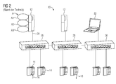
- FIG. 2 shows an automation system 10 according to the prior art in a further embodiment.
- two computing devices 12 and an input device 22 are provided.
- the automation system comprises six peripheral devices 14.
- the peripheral devices 14 and network devices 26 are connected to the computing devices 12 and the input device 22, respectively.
- a uniform data bus 28 is used, which may be designed, for example, as an Ethernet connection.
- Peripheral devices 14 are permanently assigned to a computing device 12. Again, the automation task A and all subtasks A1, A2 and A3 is calculated with a computing device 12.
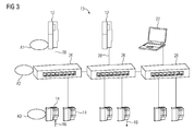
- FIG. 3 shows an embodiment of the automation system 10 according to the invention in a schematic representation.
- the physical topology of the automation system 10 is the same as that in FIG. 2 is shown. However, the logical topology differs from that associated with FIG. 2 has been described.
- the strict assignment of the peripheral devices 14 to the computing devices 12 is resolved.
- the automation devices are all equal partners in the automation system 10.
- the automation task A is divided here into the subtasks A1, A2, and A3.
- the distribution of subtasks A1, A2, A3 is the task of automation engineering takes place offline engineering tool on the basis of a list, which represents the existing in reality automation devices of the automation system 10. This distribution of subtasks A1, A2, A3 can be done, for example, by an operator input of the input device 22.
- the dynamic distribution of the individual subtasks A1, A2, A3 to the existing automation devices takes place in two steps. The first steps are assigned to the subtasks offline in automation devices and in the second step, the subtasks A1, A2, A3 are downloaded online and brought to completion.
- the first category of subtasks A1, A2, A3 are device tasks. These are assigned to the automation devices, in particular the peripheral devices 14, based on the physical wiring in the automation system.
- the second category of subtasks A1, A2, A3 comprises computational sub-tasks. These are assigned to the automation devices as a function of the already distributed device tasks. For this purpose, the automation devices, in particular the peripheral devices 14, send out corresponding data with symbols, by means of which their position in the automation system 10 can be determined.
- the automation device can be assigned a computing sub-task that has the least overall distance to all necessary automation devices. Subsequently, it is checked whether the selected automation device can provide the necessary computing power.
- the program code of the subtasks is dynamically executed on automation devices by downloading the program code.
- a description is loaded in addition to the program code, which contain for the execution of relevant parameters, such as a priority and a time behavior.
- the peripheral devices 14 preferably device tasks are brought to expiration. This can be done on the peripheral devices 14 corresponding subtasks to the expiration, which require low processing power.
- the peripheral devices 14 carry out the subtask A3, which includes the "measuring".
- the flow in an automation system with at least one peripheral device 14 can be determined. In this case, the flow can be determined with a plurality of peripheral devices 14. It is also conceivable that the flow is determined at several times with a peripheral device 14.
- subtask A2 the "mean” is determined with the network device 26. It is also conceivable that the mean value is determined with a peripheral device 14. The determined mean value is transmitted to the computing device 12, on which the subtask A1 "control" is performed. Thus, with the computing device 12, a corresponding manipulated variable can be determined, which is transmitted as the peripheral devices 14, by means of which the flow in the automation system is controlled.
Landscapes
- Engineering & Computer Science (AREA)
- Manufacturing & Machinery (AREA)
- Physics & Mathematics (AREA)
- General Physics & Mathematics (AREA)
- Automation & Control Theory (AREA)
- Human Computer Interaction (AREA)
- General Engineering & Computer Science (AREA)
- Quality & Reliability (AREA)
- Programmable Controllers (AREA)
Priority Applications (1)
| Application Number | Priority Date | Filing Date | Title |
|---|---|---|---|
| EP12172971.9A EP2677381A1 (fr) | 2012-06-21 | 2012-06-21 | Procédé destiné au fonctionnement d`un système dýautomatisation |
Applications Claiming Priority (1)
| Application Number | Priority Date | Filing Date | Title |
|---|---|---|---|
| EP12172971.9A EP2677381A1 (fr) | 2012-06-21 | 2012-06-21 | Procédé destiné au fonctionnement d`un système dýautomatisation |
Publications (1)
| Publication Number | Publication Date |
|---|---|
| EP2677381A1 true EP2677381A1 (fr) | 2013-12-25 |
Family
ID=46724203
Family Applications (1)
| Application Number | Title | Priority Date | Filing Date |
|---|---|---|---|
| EP12172971.9A Withdrawn EP2677381A1 (fr) | 2012-06-21 | 2012-06-21 | Procédé destiné au fonctionnement d`un système dýautomatisation |
Country Status (1)
| Country | Link |
|---|---|
| EP (1) | EP2677381A1 (fr) |
Citations (6)
| Publication number | Priority date | Publication date | Assignee | Title |
|---|---|---|---|---|
| US6104962A (en) * | 1998-03-26 | 2000-08-15 | Rockwell Technologies, Llc | System for and method of allocating processing tasks of a control program configured to control a distributed control system |
| US6205362B1 (en) * | 1997-11-24 | 2001-03-20 | Agilent Technologies, Inc. | Constructing applications in distributed control systems using components having built-in behaviors |
| US20060101465A1 (en) * | 2004-11-09 | 2006-05-11 | Hitachi, Ltd. | Distributed control system |
| DE102005017594A1 (de) * | 2005-04-16 | 2006-10-19 | Abb Patent Gmbh | Dezentrales Automatisierungssystem |
| EP1916578A1 (fr) * | 2006-10-24 | 2008-04-30 | Triphase NV | Système de commande de processus en temps réel |
| WO2010130503A1 (fr) * | 2009-05-12 | 2010-11-18 | Siemens Aktiengesellschaft | Procédé et dispositif pour placer des unités destinées à exécuter une application dans un système réparti |
-
2012
- 2012-06-21 EP EP12172971.9A patent/EP2677381A1/fr not_active Withdrawn
Patent Citations (6)
| Publication number | Priority date | Publication date | Assignee | Title |
|---|---|---|---|---|
| US6205362B1 (en) * | 1997-11-24 | 2001-03-20 | Agilent Technologies, Inc. | Constructing applications in distributed control systems using components having built-in behaviors |
| US6104962A (en) * | 1998-03-26 | 2000-08-15 | Rockwell Technologies, Llc | System for and method of allocating processing tasks of a control program configured to control a distributed control system |
| US20060101465A1 (en) * | 2004-11-09 | 2006-05-11 | Hitachi, Ltd. | Distributed control system |
| DE102005017594A1 (de) * | 2005-04-16 | 2006-10-19 | Abb Patent Gmbh | Dezentrales Automatisierungssystem |
| EP1916578A1 (fr) * | 2006-10-24 | 2008-04-30 | Triphase NV | Système de commande de processus en temps réel |
| WO2010130503A1 (fr) * | 2009-05-12 | 2010-11-18 | Siemens Aktiengesellschaft | Procédé et dispositif pour placer des unités destinées à exécuter une application dans un système réparti |
Similar Documents
| Publication | Publication Date | Title |
|---|---|---|
| EP2422243B1 (fr) | Commande de sécurité pour commander une installation automatisée et procédé de génération d'un programme d'application pour une commande de sécurité | |
| DE102008055660B4 (de) | Verfahren und Vorrichtung zum Zugreifen auf ein Funktionsmodul eines Automatisierungssystems | |
| EP2520991B1 (fr) | Procédé d'accès commandé au comportement d'un sous-module | |
| DE102010029952A1 (de) | Verfahren zum Integrieren von zumindest einem Feldgerät in ein Netzwerk der Automatisierungstechnik | |
| DE102007026678A1 (de) | Verfahren zum Austausch eines defekten Feldgerätes gegen ein neues Feldgerät in einem über digitalen Feldbus kommunizierenden System, insbesondere Automatisierungssystem | |
| WO2018036708A1 (fr) | Passerelle et procédé de connexion d'un système de source de données à un système informatique | |
| EP3039494B1 (fr) | Système d'automatisation | |
| EP2707999B1 (fr) | Système de traitement de signaux et procédé de traitement de signaux dans un n ud de bus | |
| EP2732347B1 (fr) | Procédé et système de répartition dynamique de fonctions de programme dans des systèmes de commande répartis | |
| EP3444682A1 (fr) | Procédé d'accouplement assisté par ordinateur d'un module de traitement dans un système technique modulaire et système technique modulaire | |
| EP3082002B1 (fr) | Commande de securite et procede de commande d'une installation automatisee | |
| DE10326542A1 (de) | Betriebsverfahren und Steuerungsprogramm für eine Zentraleinheit eines Automatisierungssystems sowie Zentraleinheit eines Automatisierungssystems und Automatisierungssystem selbst | |
| EP3268822B1 (fr) | Appareil d'établissement de projet et procédé pour configurer et/ou paramétrer des composants d'automatisation d'un système d'automatisation | |
| EP2216696B1 (fr) | Procédé et système de communication pour la configuration d'un module de communication intégré dans un module logique | |
| EP3088976B1 (fr) | Procédé de fonctionnement d'un dispositif d'automatisation et dispositif d'automatisation | |
| EP2557464A1 (fr) | Procédé destiné au fonctionnement d'un système d'automatisation | |
| EP1643679A1 (fr) | Configuration de modules dans des systèmes d'automatisation | |
| DE102010040055A1 (de) | System zur Kommunikation von mehreren Clients mit mehreren Feldgeräten in der Automatisierungstechnik | |
| EP3252549B1 (fr) | Procédé de fonctionnement d'un dispositif d'automatisation et procédé d'automatisation | |
| EP3977301A1 (fr) | Serveur de durée d'exécution destiné à la mise en oeuvre simultanée de plusieurs systèmes de durée d'exécution d'une installation d'automatisation | |
| DE10242004B4 (de) | Automatisierungseinrichtung | |
| EP3770704A1 (fr) | Système d'automatisation décentralisée en nuage | |
| EP2677381A1 (fr) | Procédé destiné au fonctionnement d`un système dýautomatisation | |
| WO2019228910A1 (fr) | Commande programmable à mémoire et procédé de fonctionnement d'une commande programmable à mémoire et produit programme informatique | |
| EP4453674A1 (fr) | Technique de paramétrage et/ou de configuration pour un dispositif basé sur un automate programmable industriel |
Legal Events
| Date | Code | Title | Description |
|---|---|---|---|
| PUAI | Public reference made under article 153(3) epc to a published international application that has entered the european phase |
Free format text: ORIGINAL CODE: 0009012 |
|
| AK | Designated contracting states |
Kind code of ref document: A1 Designated state(s): AL AT BE BG CH CY CZ DE DK EE ES FI FR GB GR HR HU IE IS IT LI LT LU LV MC MK MT NL NO PL PT RO RS SE SI SK SM TR |
|
| AX | Request for extension of the european patent |
Extension state: BA ME |
|
| STAA | Information on the status of an ep patent application or granted ep patent |
Free format text: STATUS: THE APPLICATION IS DEEMED TO BE WITHDRAWN |
|
| 18D | Application deemed to be withdrawn |
Effective date: 20140626 |