EP2677457B1 - Procédé et système de localisation d'un billet électronique dans un moyen de transport - Google Patents
Procédé et système de localisation d'un billet électronique dans un moyen de transport Download PDFInfo
- Publication number
- EP2677457B1 EP2677457B1 EP12173223.4A EP12173223A EP2677457B1 EP 2677457 B1 EP2677457 B1 EP 2677457B1 EP 12173223 A EP12173223 A EP 12173223A EP 2677457 B1 EP2677457 B1 EP 2677457B1
- Authority
- EP
- European Patent Office
- Prior art keywords
- ticket
- transmission
- reception unit
- transportation vehicle
- relative location
- Prior art date
- Legal status (The legal status is an assumption and is not a legal conclusion. Google has not performed a legal analysis and makes no representation as to the accuracy of the status listed.)
- Active
Links
Images






Classifications
-
- G—PHYSICS
- G06—COMPUTING OR CALCULATING; COUNTING
- G06K—GRAPHICAL DATA READING; PRESENTATION OF DATA; RECORD CARRIERS; HANDLING RECORD CARRIERS
- G06K7/00—Methods or arrangements for sensing record carriers, e.g. for reading patterns
- G06K7/0008—General problems related to the reading of electronic memory record carriers, independent of its reading method, e.g. power transfer
-
- G—PHYSICS
- G06—COMPUTING OR CALCULATING; COUNTING
- G06Q—INFORMATION AND COMMUNICATION TECHNOLOGY [ICT] SPECIALLY ADAPTED FOR ADMINISTRATIVE, COMMERCIAL, FINANCIAL, MANAGERIAL OR SUPERVISORY PURPOSES; SYSTEMS OR METHODS SPECIALLY ADAPTED FOR ADMINISTRATIVE, COMMERCIAL, FINANCIAL, MANAGERIAL OR SUPERVISORY PURPOSES, NOT OTHERWISE PROVIDED FOR
- G06Q50/00—Information and communication technology [ICT] specially adapted for implementation of business processes of specific business sectors, e.g. utilities or tourism
- G06Q50/40—Business processes related to the transportation industry
-
- G—PHYSICS
- G07—CHECKING-DEVICES
- G07B—TICKET-ISSUING APPARATUS; FARE-REGISTERING APPARATUS; FRANKING APPARATUS
- G07B15/00—Arrangements or apparatus for collecting fares, tolls or entrance fees at one or more control points
- G07B15/02—Arrangements or apparatus for collecting fares, tolls or entrance fees at one or more control points taking into account a variable factor such as distance or time, e.g. for passenger transport, parking systems or car rental systems
-
- G—PHYSICS
- G07—CHECKING-DEVICES
- G07C—TIME OR ATTENDANCE REGISTERS; REGISTERING OR INDICATING THE WORKING OF MACHINES; GENERATING RANDOM NUMBERS; VOTING OR LOTTERY APPARATUS; ARRANGEMENTS, SYSTEMS OR APPARATUS FOR CHECKING NOT PROVIDED FOR ELSEWHERE
- G07C9/00—Individual registration on entry or exit
- G07C9/20—Individual registration on entry or exit involving the use of a pass
- G07C9/28—Individual registration on entry or exit involving the use of a pass the pass enabling tracking or indicating presence
Definitions
- the present invention relates to a method and a system for locating an e-ticket in a means of transport according to claim 1 or claim 14.
- the present invention is therefore based on the object of specifying a method and system for locating an e-ticket in a means of transport, which allows a precise localization of the location of the e-ticket in the means of transport, thereby enabling a "stay-active" detection, for example a Classification 1st class / 2.
- Class for a car containing both classes be it 1st class and 2nd class or restaurant and 2nd class such as e.g. is common among Swiss transport companies such as RhB, ZVV, SGV or SBB.
- the localization of the location of the e-ticket in a means of transport is referred to as a relative location, relative to the location within the means of transport considered.
- FIG. 1 shows a railway carriage 30 as an example of a means of transport 30.
- the railway carriage 30 in two compartments 1. Cl. (1st class, left) and 2nd Cl. (2nd class, right) articulated, see the partition wall 34 in the entrance area 31.
- two transceiver units 20 1 and 20 2 are installed on the ceiling of the railway carriage 30, two transceiver units 20 1 and 20 2 are installed.
- the e-ticket 10 is located in the detection area 21 1 and 21 2 of both transmitting / receiving units 20 1 and 20 2 . Also on the reception levels may under certain circumstances no clear demarcation between 1st and 2nd Cl. be made because the measurement accuracy is often insufficient, z. B. by standing in the entrance area persons. If communication now takes place between e-ticket 10 and transmitting / receiving unit 20 1 , then, in the course of this communication or as part of a separate measuring procedure, between transmitting / receiving units 20 1 and e-ticket 10 from transmitting / receiving unit 20 1 seen from the angle between the e-ticket 10 and a reference direction 28, here the vertical 28, are determined.
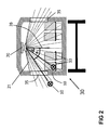
- FIG. 2 shows a cross-sectional view of a railway car 30 for explaining an embodiment of the present invention for an angle measurement in a reference plane 38, which is perpendicular to the longitudinal axis of a railway car.
- the measurement of the angles ⁇ 1, ⁇ 2 is an exact distinction as to whether an e-ticket 10 is inside or outside the means of transport 30.
- the transmitting / receiving unit 20 z. B. through the windows 35 by radio also communicate with e-tickets 10, which are located outside the means of transport 30.
- the imaged transmitting / receiving unit 20 on the ceiling of the railroad car 30 can also be an e- Ticket 10 of a person to be recorded on the platform.
- the necessary communication between transmitting / receiving unit 20 and e-tickets 10 could z. B. through the windows 35 of the railway carriage 30 through. In such a case no fare booking may be made to the person on the platform.
- a passenger who is inside the train and carries the e-ticket 10 should be reliably recognized. As shown, you can use an angle measurement - see the angles ⁇ 1, ⁇ 2 in the FIG.
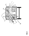
- the location of an e-ticket 10 in a means of transport can also be carried out by measuring the distance d between the e-ticket 10 and one or more transmitting / receiving units 20.
- This is exemplified by the FIG. 3 explained. It is assumed that a passenger resides on a seat 33 and he has his e-ticket 10 in the Trouser pocket has. Here, the distance measurement is used to exactly distinguish whether an e-ticket 10 is inside or outside the means of transport 30.
- the transmitting / receiving units 20 1 and 20 2 z. B. communicate through the windows 35 by radio with e-tickets 10, which are located outside the transport 30.
- the e-ticket can also be activated by the transmitter / receiver units 20 1 and 20 2 installed on the ceiling 10 of a person on the platform.
- the necessary communication between transmitting / receiving units 20 1 and 20 2 and the e-ticket could, for. B. through the windows 35 of the railway car through. In such a case no fare booking may be made to the person on the platform.
- the transmitter / receiver units 20 1 and 20 2 installed on the ceiling 10 of a person on the platform.
- the necessary communication between transmitting / receiving units 20 1 and 20 2 and the e-ticket could, for. B. through the windows 35 of the railway car through. In such a case no fare booking may be made to the person on the platform.
- the position is determined in terms of two dimensions.
- a third transmitting / receiving unit 20 an exact position determination in space could also be carried out.
- all methods known from the field of radar system technology appear suitable for distance measurement.
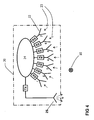
- FIG. 4 shows the circuit and functional structure of a transmitting / receiving unit 20 with directional antennas for the location of an e-ticket 10 via a measurement of the angle ⁇ .
- the transmitting / receiving unit 20 contains a plurality of directional receiving antennas 22, whose main axes point in different directions (shown corresponding to a possible spatial arrangement).
- the individual antennas 22 are each connected to a separate receiver RX.
- the receivers RX provide a value for the reception level when data communication takes place. Is the e-ticket 10 z. B.
- the angle ⁇ to the e-ticket 10 can be determined in certain steps or with a certain granularity, for example by interpolation. By comparing with reception levels of several antennas / receivers RX, positions between the main axes of the antennas can also be determined. For the sending of data packets from the transmitting / receiving unit 20 to the e-tickets 10, the illustrated transmission block is used.
- the e-ticket should be 10 for such functionality should be equipped with an omnidirectional antenna, ie the antenna in the e-ticket 10 should not have a preferred direction.
- FIG. 5 Another embodiment of a transmitting / receiving unit 20 shows FIG. 5 , Here, the functional units for data communication and for measuring the angle ⁇ are separated from each other.
- the data communication 41 takes over the in the FIG. 5
- the measurement of the angle ⁇ takes place with the aid of four reception branches. This is in the FIG. 5 with "channel 1" to "Channel 4", wherein the individual antennas are arranged spatially next to each other.
- the e-ticket transmits a continuous wave radio signal in the form of a frequency ramp. This frequency ramp is received over the four channels and each converted to an intermediate frequency level by means of a mixer fed by a common LO signal.
- the thus obtained intermediate frequency signals are fed via a bandpass filter to inputs of A / D converters and evaluated by a microcontroller.
- the common LO signal goes through during the measurement, in time to match the frequency ramp sent by the e-ticket 10, also a frequency ramp, wherein z. B. a certain frequency difference to the frequency ramp of the e-ticket 10 is maintained.
- a similar intermediate frequency results for the four channels, which is dependent on the distance d between e-ticket 10 and transmitting / receiving unit 20: as the distance increases, the resulting intermediate frequency also increases.
- the individual reception branches are coherently operated to each other, ie they are ideally constructed identically and are fed with the same LO signal (same phase). Like in the FIG.
- the illustrated method for determining an angle information is one of the methods known from the field of radar system technology ("state of the art"), however, the use of recognizing the position of an e-ticket 10 in the field of e-ticketing is new.
- all methods known from the field of radar system technology for angle measurement can be used. These methods are usually based on a direct or indirect measurement of propagation times of a radio signal, on the comparison of phase relationships of radio signals or simply on a spatial arrangement of multiple directional antennas.
- the radio signals used may be continuous-wave signals CW, FMCW or even pulse-shaped signals. It is also possible to carry out angle measurements on the basis of emitted radar signals with successively set frequency steps (stepped frequency method).
- a particularly advantageous solution results if, for the implementation of a method for angle measurement not only on the side of the e-ticket 10, but also on the side of the transmitting / receiving unit 20 no additional hardware effort is required, but already existing facilities and Functions in the system can be used.
- the radar signal emitted for the purpose of an angle measurement must be a temporal change, for. In frequency or in phase.
- the sending of data packets also represents a temporal change, so that the data packets exchanged between the e-ticket 10 and the transmitting / receiving unit 20 in any case can also be evaluated with regard to an angle measurement.
- available on the market radio communication modules can be, for. B.
- FIG. 6 shows a particularly interesting embodiment in which can be made with comparatively little effort, a distinction between the two classes in a railway carriage 30.
- An installed transceiver unit 20 with two antennas is located centrally above the boundary between 1. Cl. and 2. Cl.
- the distinction between the two classes is made by detection areas 21 1 and 21 2 defined via the antenna directivity characteristic. Either can only take place via one of the two antennas of the transmitting / receiving unit 20, a communication with the e-ticket 10, or it is at least on the respective reception levels an assignment to a class possible.
- the transmitting / receiving unit 20 may be equipped with two communication modules, each of which is connected to its own antenna, or with a communication module to which two antennas can be connected.
- the 1st Cl. would be assigned.
- the arrangement just presented can also be combined with the other methods described above.
- FIG. 7 shows a Dosto 30.
- the Dosto has only seats 2 on the upper floor. Cl. on, while in the basement left seats in 1st Cl. and right seats in 2nd Cl. available.
- the entrance area 31 is adjoined by an access area 32, which provides access to the upper floor.
- a transmitting / receiving unit 20 is mounted on the ceiling between the upper floor and the basement. This transmitting / receiving unit 20 is above the dividing wall 34 of 1. Cl. / Entrance 31 arranged.
- an e-ticket 10 is one in the 1st Cl. seated passenger is assigned. Another e-ticket 10 is located on a passenger in the upper floor of the Dostos 30.
- This transmitting / receiving unit 20 has three antennas 27 1 , 27 2 and 27 3 , each for the determination of the angle ⁇ .
- Transceiver unit 20 As with the Figures 2 and 3 explained, with a three antennas 27 1 , 27 2 and 27 3 provided with the transmitting / receiving unit 20, the assignment of an e-ticket 10 are made to a car class. In the example according to the FIG. 7 is denoted by reference numeral 28, a so-called reference plane. Due to a comparison, the measured angle ⁇ 3 makes it possible to conclusively make this assignment to the 2. Cl.
- FIG. 8 shows a circuit arrangement for a distance measurement with an approach known from radar system technology.
- the transmitting / receiving unit 20 includes other components, such.
- a security controller for authentication and encryption of data, an interface for communication with a parent unit and a power supply unit.
- the e-ticket 10 also contains a radio communication module and an antenna for data communication 41 with the transceiver unit 20 and components with the functionality of a transponder for a radar distance measuring system: an antenna and a "backscatter modulator" designated function block, the is controlled by the microcontroller also included.
- a security controller for authentication and encryption of data in the e-ticket 10 as well as a battery and an LF module with the associated antenna.
- the e-ticket is "woken up" when entering the public transport 30 from a rest state via the LF module. If a first data exchange has now taken place between the transmitting / receiving unit 20 and the e-ticket 10, then a distance measurement takes place in the further course: A transmission signal 40 generated by the transceiver and the antenna is transmitted by the transmitting / receiving unit 20 in the form of a VCO Frequency ramp sent out. This radio signal 40 may be different from the signals of the data communication 41. The radio signal 40 is therefore also called radio communication 40 to distinguish it from the data communication 41.
- the transmission mixer has the characteristic that its isolation between the LO and the RF terminal is kept deliberately low, so that the generated radio signal with low attenuation can reach the antenna.
- the transmitted radio signal 40 reaches the corresponding antenna in the e-ticket 10.
- the antenna is equipped with a component called “backscatter modulator” whose complex impedance can be varied via a control input in a suitable form.
- the input resistance of this modulator can be almost perfectly switched back and forth between the state “open” and the state “short-circuited” via a logic control signal. Both states of the modulator result in that the incoming radio signal is picked up by the antenna, forwarded to the modulator, reflected by the modulator (since strong mismatching) and in turn emitted via the antenna to the transceiver unit 20.
- the incoming radio signal 40 is reflected by the e-ticket, only in accordance with the instantaneous state of the modulator with a variable phase position.
- the reflected signal ideally phase angles that differ by 180 degrees from each other.
- the microcontroller in the e-ticket constantly switches the control signal of the modulator at a constant frequency. Since the microcontroller is clocked by means of a quartz, the frequency for the switching operation can be generated with a comparatively high accuracy.
- the radio signal for distance measurement reflected by the e-ticket 10 is picked up again by the corresponding antenna 27 in the transmitting / receiving unit 20 and returns to the transmission mixer.
- a mixing process with the current signal of the VCO. Since due to the duration of the radio signal until its return to the transmitting / receiving unit 20, a distance-dependent period has elapsed and the frequency of the VCO has already changed a little during this period, results in the output of the mixer as a "2F signal" in principle a distance-dependent difference frequency f diff_Ticket according to the FMCW distance measuring method .
- the frequency difference appears in the spectrum this "IF signal" again in the form of a two-sideband modulation around the modulation frequency (and further multiples of the modulation frequency) of the e-ticket 10 around.
- FIG. 9 The spectrum of the IF signal at the output of the transmission mixer is shown above:
- further spectral components f diff2 , f diff3 and f diff4 can be seen.
- These components are exemplary of the radio signals reflected by further objects in the vicinity of the arrangement: the radio signal for distance measurement emitted by the transmitting / receiving unit 20 is unintentionally also reflected by further objects, which results in further spectral components.
- the difference signal originating from the e-ticket 10 can be distinguished from the other difference signals: If the IF signal passes through the band-pass filter shown in the block diagram, signal components with a frequency clearly below (f mod - f diff_max ) is suppressed, so that the in FIG. 9 shown below spectrum. In the FIG. 9 the cutoff frequencies (f mod - f diff max ) and (f mod + f diff max ) are entered for the bandpass filter.
- the AF signal is detected by the A / D converter and subjected to signal processing by means of the microcontroller.
- the signal is mixed numerically with f mod , subjected to a low-pass filtering (so that only the signal component at f mod remains) and determined with appropriate (and known from the field of radar system technology) method, the exact position of the signal component in the spectrum. Advantages of the solution shown are the low power consumption and the relatively low cost with low component costs on the side of the e-ticket 10.
- the backscatter modulator can be z. B. by one, if appropriate, adapted to realize FET, in which the control input to the gate terminal of the FET and the ground are connected to the source terminal. Now, if the voltage at the gate of the FET is changed, so also change its channel properties and thus the complex impedance between the drain and the source terminal.
- the backscatter modulator can also be realized with the help of a varactor diode or z. B. by a ready available as a component RF switch. Most of the proposed variants have in common that a complex impedance can be influenced via a control voltage at the input and that in most cases only a very small current flows into the control input of the device. Since the e-ticket 10 is battery powered, low power consumption appears to be very beneficial.
- the described backscatter modulator which variably terminates the base of an antenna in response to an applied control voltage and its use in transponders for radar distance measurement can be considered as prior art; see, for. B.
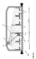
- FIG. 10 shows a particularly interesting embodiment in which can be made with comparatively little effort, a distinction between the two classes in a railway carriage 30.
- An installed transceiver unit 20 is located, for example, in the middle of the first Cl. belonging vehicle area.
- an e-ticket 10 is shown, whose carrier person would be assigned to the 1st class. With the given spatial arrangement, an assignment of the e-ticket 10 to one of the two classes is possible solely by measuring the distance between the transmitting / receiving unit 20 and the e-ticket 10, even if a certain "blurring" must be expected in the transition area ,
- the data packets sent by the standard-compliant radio interface modules in the e-ticket 10 and auxiliary transponder 11 can only be transmitted at precisely the same time, whereby a time difference ⁇ offset between the data packets transmitted by e-ticket 10 and auxiliary transponder 11 arises.
- ⁇ TH is a transit time difference
- this value can have a positive or negative sign in the given example.
- d TH can also have a positive or negative sign, which can be assigned to a position of the e-ticket 10 on the right (positive sign) or left (negative sign) of the auxiliary transponder 11.
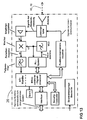
- FIG. 12 shows the block diagram of an e-ticket 10. It differs, as already described above, not that of an e-ticket 10, the functionality for Distance measurement not supported.
- the block diagram of the auxiliary transponder 11 described above is very similar to that of the e-ticket 10; In practice, however, the auxiliary transponder 11 is not supplied with electrical energy via a battery but via a fixed connection.
- Both the e-ticket 10 according to the FIG. 12 as well as according to the FIG. 8 contain an LF interface and a wake-up receiver. This is - as already stated in the introduction - immaterial to the present invention.
- the invention covers in particular the case in which the e-tickets 10 are brought into the operating state other than by a wake-up signal, it is also that the e-tickets 10 thanks to the more powerful batteries and even smaller energy consumption thanks to integrated components autonomy of several years of continuous operation.
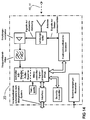
- FIG. 13 shows a transmitting / receiving unit 20 with a power divider, which splits the signals from and to the antenna to the radio communication module and the function blocks for distance determination.
- the module for wireless data communication is used here exclusively for the exchange of data packets. Data packets also inform about the time points of measuring processes.
- the incoming via antenna and power divider signals for distance measurement (sent by e-ticket 10 and auxiliary transponder 11 data packets) are first amplified and then set using a local oscillator (constructed in the example of a VCO and a PLL block) and a mixer to an intermediate frequency level , Subsequently, the frequency range of interest (usually chosen slightly larger than the maximum usable bandwidth for all channels in the frequency band used) is filtered out using a low-pass filter and fed to an analog-to-digital converter. Its sampling rate is at least twice as high as the highest frequency components that can occur at the input of the A / D converter (sampling theorem).
- the analog signal for example, first recorded for a certain time and in a local Memory stored. Subsequently, the individual received channels are treated separately from each other. Often, the modulation method DSSS is used in modern radio communication modules. It is also possible to use further customary modulation methods for distance determination with the aid of the described method. Center frequency, bandwidth of a single channel and the frequency of a single step (so-called "chip rate”) are known, so that it is easy to determine the useful content and individual properties of the received data packets.
- FIG. 14 the block diagram of another possible variant for a transmitting / receiving unit 20 to the method described above is shown.
- the difference to in FIG. 12 system shown here is that here the radio signal for distance measurement is not first implemented by means of a mixer to an intermediate frequency level, but is scanned directly via a very fast A / D converter and stored in sections in a fast buffer memory. The conversion to a suitable frequency level or the assignment to the individual frequency channels used then takes place here numerically.
- auxiliary transponders 11 can be constructed in principle exactly the same as the e-tickets, but are permanently installed in certain locations in the car.
- these auxiliary transponders 11 could be powered by batteries or by permanently installed lines with energy.
- the transmitting / receiving unit 20 precisely locates the e-tickets 10, since a comparison between the measured values with respect to the relevant auxiliary transponder 11 can be drawn with a known position and with respect to the e-ticket 10.
- Advantageous installation positions for an auxiliary transponder 11 is the transition region 34 between two classes in a means of transport 30.
- auxiliary transponder 11 could be located in the partition wall 34 between the entrance area 31 and the 1st class seats.
- a transmitting / receiving unit 20 were also installed under the ceiling of the car just above the transition from 1st to 2nd class (in Fig. 11 not shown), so this auxiliary transponder 11 can serve in an additional angle determination angle to improve the measurement accuracy and reliability.
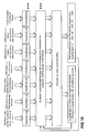
- Fig. 15 is an intermediate frequency signal spectrum as already in Fig. 9 shown in the lower area, but not in an idealized representation, but as it is under difficult conditions in the car, with many passengers and multiple reflections, as occurs in practice:
- f mod - f diff points
- f mod + f diff points
- the cause of a wide dome can be z.
- Blurred evaluation methods such.
- fuzzy algorithms help determine the exact location of the tip of the dome, and thus the distance between the transmitting / receiving unit 20 and e-ticket 10 despite the unfavorable Conditions to determine relatively accurately.
- these fuzzy methods can also be used in FMCW distance measurements or angle measurement methods.
- the neural network either in the development of the system or at the time of installation in the means of transport 30, must undergo a learning process in which many possible positions of the e-ticket 10 are given under as many different boundary conditions and the associated desired results.
- the evaluation of signals from radio systems for position determination with the aid of neural networks is known, new, however, is the application of such methods in connection with e-ticketing systems and the feeding of further specific information (such as the number of registered e-tickets in the car concerned).
- the consideration of the time course of measurement signals (history) represented in connection with an evaluation via a neural network can also be used in conjunction with the previously described evaluation methods, here of course in the form of concrete lists with n preceding measured values. Under certain circumstances, this can also increase measurement accuracy and reliability (eg via plausibility tests) of the system.
Landscapes
- Engineering & Computer Science (AREA)
- Theoretical Computer Science (AREA)
- Business, Economics & Management (AREA)
- Physics & Mathematics (AREA)
- General Physics & Mathematics (AREA)
- Economics (AREA)
- Computer Vision & Pattern Recognition (AREA)
- Health & Medical Sciences (AREA)
- Artificial Intelligence (AREA)
- General Health & Medical Sciences (AREA)
- Human Resources & Organizations (AREA)
- Marketing (AREA)
- Primary Health Care (AREA)
- Strategic Management (AREA)
- Tourism & Hospitality (AREA)
- General Business, Economics & Management (AREA)
- Radar Systems Or Details Thereof (AREA)
- Devices For Checking Fares Or Tickets At Control Points (AREA)
Claims (22)
- Procédé d'enregistrement d'une présence définie de billets électroniques (10) dans un moyen de transport (30), lesquels billets électroniques (10) contiennent des moyens d'émission/réception pour une communication (41) avec une unité d'émission/réception (20) placée dans le moyen de transport (30), communication (41) durant laquelle des données d'enregistrement de la présence définie sont transmises à l'unité d'émission/réception (20) ;
caractérisé en ce que
au moyen d'une radiocommunication (40) entre un billet électronique (10) et l'unité d'émission/réception (20), un enregistrement de l'emplacement relatif (ϕ, (ϕ1, ϕ2 ; d, d1, d2, d3, d4 ; dT1, dT2 ; dTH) du billet électronique (10) par rapport au moyen de transport (30) est effectué dans l'unité d'émission/réception (20). - Procédé selon la revendication 1,
caractérisé en ce que
l'emplacement relatif du billet électronique (10) est déterminé par une mesure de l'angle (ϕ, ϕ1, ϕ2, ϕ3) entre l'unité d'émission/réception du ticket électronique (10) et un sens de référence (28) ou un plan de référence (28) à l'intérieur du moyen de transport (30). - Procédé selon la revendication 2,
caractérisé en ce que
le plan de référence (28) par rapport au moyen de transport (30) est fixé verticalement ou horizontalement. - Procédé selon l'une des revendications 1 à 3,
caractérisé en ce que
l'unité d'émission/réception (20) est installée à une frontière (34) entre deux zones distinctes (1. Cl., 2. Cl.) à l'intérieur du moyen de transport (30), et en ce qu'on utilise l'angle (ϕ, ϕ1, ϕ2, ϕ3) entre le billet électronique (10) et une ligne de référence (34) ou un plan de référence (34) tel que vu de l'unité d'émission/réception (20) pour l'affectation à l'une des deux zones (1. Cl., 2. Cl.). - Procédé selon l'une des revendications 1 à 4,
caractérisé en ce que
l'emplacement relatif du billet électronique (10) est déterminé par une mesure de la distance (d, d1, d2, d3, d4 ; dT1, dT2 ; dTH) entre l'unité d'émission/réception (20) et le billet électronique (10). - Procédé selon la revendication 5,
caractérisé en ce que
la mesure de la distance entre l'unité d'émission/réception (20) et le billet électronique (10) se fait par le biais du temps de parcours d'un signal (40) transmis entre le billet électronique (10) et l'unité d'émission/réception (20) ou par le biais d'une évaluation d'un niveau du signal (40) reçu par l'unité d'émission/réception (20). - Procédé selon la revendication 5 ou 6,
caractérisé en ce que
il est prévu au moins un transpondeur auxiliaire (11) placé de manière fixe dans le moyen de transport (30), permettant ainsi d'effectuer l'enregistrement de l'emplacement relatif (dT1, dT2 ; dTH ; dH1, dH2) du billet électronique (10) par rapport au moyen de transport (30) par le biais de l'emplacement (dH1, dH2) connu dans le moyen de transport (30) du transpondeur auxiliaire (11). - Procédé selon la revendication 7,
caractérisé en ce que le transpondeur auxiliaire (11) est relié par fil à une unité d'émission/réception (20). - Procédé selon la revendication 5 ou 6,
caractérisé en ce que- il est prévu au moins un transpondeur auxiliaire (11) placé de manière fixe dans le moyen de transport (30), et en ce que l'emplacement relatif (dH, dH2) de celui-ci dans le moyen de transport est mémorisé avec des données (dH1, dH2) dans l'unité d'émission/réception (20),- au moyen d'une autre radiocommunication (40) entre le transpondeur auxiliaire (11) et l'unité d'émission/réception (20), un enregistrement de l'emplacement relatif (dH1, dH2,) du transpondeur auxiliaire (10) par rapport au moyen de transport (30) est effectué et comparé aux données (dH1, dH2) mémorisées dans l'unité d'émission/réception (20), et est enregistré en tant qu'écart, et en ce que- l'enregistrement de l'emplacement relatif (d) du billet électronique (10) par rapport au moyen de transport (30) est compensé par ledit écart. - Procédé selon l'une des revendications 1 à 9,
caractérisé en ce que
l'emplacement relatif (ϕ, ϕ1, ϕ2 ; d, d1, d2, d3, d4 ; dT1, dT2 ; dTH) du billet électronique (10) par rapport au moyen de transport (30) est déterminé par plusieurs unités d'émission/réception (20 ; 201, 202). - Procédé selon l'une des revendications 1 à 10,
caractérisé en ce que
on utilise pour la radiocommunication (40) la communication (41) destiné à l'enregistrement de la présence définie du billet électronique (10), de sorte qu'aucune fréquence supplémentaire n'est nécessaire pour l'enregistrement de l'emplacement relatif (ϕ, ϕ1, ϕ2 ; d, d1, d2, d3, d4 ; dT1, dT2 ; dTH) du billet électronique (10). - Procédé selon l'une des revendications 1 à 11,
caractérisé en ce que
les données de l'emplacement relatif (ϕ, ϕ1, ϕ2 ; d, d1, d2, d3, d4) d'un billet électronique (10) sont soumises à un procédé d'évaluation floue - de préférence des algorithmes flous - pour assurer une détermination plus précise de l'emplacement relatif du billet électronique (10). - Procédé selon l'une des revendications 1 à 11,
caractérisé en ce que
les données de l'emplacement relatif (ϕ, ϕ1, ϕ2 ; d, d1, d2, d3, d4) d'un billet électronique (10) sont déterminées à plusieurs reprises pour assurer au moyen d'un réseau neuronal une détermination de l'emplacement relatif du billet électronique (10) avec mention d'une probabilité définie. - Système d'enregistrement d'une présence définie de billets électroniques (10) dans un moyen de transport (30), lesquels billets électroniques (10) contiennent un moyen d'émission/réception pour une communication (41) avec une unité d'émission/réception (20) placée dans le moyen de transport (30), communication (41) durant laquelle des données d'enregistrement de la présence définie sont transmises à l'unité d'émission/réception (20) ;
caractérisé en ce que
l'unité d'émission/réception (20) comporte des moyens d'enregistrement de l'emplacement relatif (ϕ, ϕ1, ϕ2 ; d, d1, d2, d3, d4 ; dT1, dT2 ; dTH) du billet électronique (10) par rapport au moyen de transport (30) dans l'unité d'émission/réception (20), ces moyens étant prévus pour une radiocommunication (40) entre les billets électroniques (10) et l'unité d'émission/réception (20). - Système selon la revendication 14,
caractérisé en ce que
l'emplacement relatif du billet électronique (10) est déterminé par une mesure de l'angle (ϕ, ϕ1, ϕ2, ϕ3) entre l'unité d'émission/réception du ticket électronique (10) et un sens de référence (28) ou un plan de référence (28) à l'intérieur du moyen de transport (30), l'unité d'émission/réception (20) comprenant une pluralité d'antennes (22), orientées de manière différente, pour la mesure de l'angle. - Système selon la revendication 14 ou 15,
caractérisé en ce que
l'unité d'émission/réception (20) est installée à une frontière (34) entre deux zones distinctes (1. Cl., 2. Cl.) à l'intérieur du moyen de transport (30), et en ce qu'on utilise l'angle (ϕ, ϕ1, ϕ2, ϕ3) entre le billet électronique (10) et une ligne de référence (34) ou un plan de référence (34) tel que vu de l'unité d'émission/réception (20) pour l'affectation à l'une des deux zones (1. Cl., 2. Cl.). - Procédé selon l'une des revendications 14 à 16,
caractérisé en ce que
l'emplacement relatif du billet électronique (10) est déterminé par une mesure de la distance (d, d1, d2, d3, d4 ; dT1, dT2 ; dTH) entre l'unité d'émission/réception (20) et le billet électronique (10), ladite distance étant déterminée à partir du temps de parcours d'un signal (40) transmis entre le billet électronique (10) et l'unité d'émission/réception (20) ou à partir du niveau du signal (40) reçu par l'unité d'émission/réception (20), et l'unité d'émission/réception (20) ayant pour cela la configuration telle que représentée en Fig. 13 et 14 ou comportant un module de radiocommunication qui fournit des valeurs des niveaux de réception de paquets de données reçus. - Système selon la revendication 17,
caractérisé en ce que
il est prévu au moins un transpondeur auxiliaire (11) placé de manière fixe dans le moyen de transport (30), permettant ainsi d'effectuer l'enregistrement de l'emplacement relatif (dT1, dT2 ; dTH ; dH1, dH2) du billet électronique (10) par rapport au moyen de transport (30) par le biais de l'emplacement (dH1, dH2) connu dans le moyen de transport (30) du transpondeur auxiliaire (11). - Système selon la revendication 18,
caractérisé en ce que
le transpondeur auxiliaire (11) est relié par fil à une l'unité d'émission/réception (20). - Système selon la revendication 17,
caractérisé en ce que- il est prévu au moins un transpondeur auxiliaire (11) placé de manière fixe dans le moyen de transport (30), et en ce que l'emplacement relatif (dH1, dH2) de celui-ci dans le moyen de transport est mémorisé avec des données (dH1, dH2) dans l'unité d'émission/réception (20),- au moyen d'une autre radiocommunication (40) entre le transpondeur auxiliaire (11) et l'unité d'émission/réception (20), un enregistrement de l'emplacement relatif (dH1', dH2') du transpondeur auxiliaire (10) par rapport au moyen de transport (30) est effectué et comparé aux données (dH1, dH2) mémorisées dans l'unité d'émission/réception (20), et est enregistré en tant qu'écart, et en ce que- l'enregistrement de l'emplacement relatif (d) du billet électronique (10) par rapport au moyen de transport (30) est compensé par ledit écart. - Système selon l'une des revendications 14 à 20,
caractérisé en ce que
les données de l'emplacement relatif (ϕ, ϕ1, ϕ2 ; d, d1, d2, d3, d4) d'un billet électronique (10) sont soumises à un procédé d'évaluation floue implémenté dans l'unité d'émission/réception (20) - de préférence des algorithmes flous - pour assurer une détermination plus précise de l'emplacement relatif du billet électronique (10). - Procédé selon l'une des revendications 14 à 20,
caractérisé en ce que
les données de l'emplacement relatif (ϕ, ϕ1, ϕ2 ; d, d1, d2, d3, d4) d'un billet électronique (10) sont déterminées à plusieurs reprises pour assurer, au moyen d'un réseau neuronal implémenté dans l'unité d'émission/réception (20), une détermination de l'emplacement relatif du billet électronique (10) avec mention d'une probabilité définie.
Priority Applications (3)
| Application Number | Priority Date | Filing Date | Title |
|---|---|---|---|
| EP12173223.4A EP2677457B1 (fr) | 2012-06-22 | 2012-06-22 | Procédé et système de localisation d'un billet électronique dans un moyen de transport |
| PL12173223T PL2677457T3 (pl) | 2012-06-22 | 2012-06-22 | Sposób oraz system do lokalizacji e-biletu w środku transportu |
| ES12173223.4T ES2536118T3 (es) | 2012-06-22 | 2012-06-22 | Procedimiento y sistema de localización de un billete electrónico en un medio de transporte |
Applications Claiming Priority (1)
| Application Number | Priority Date | Filing Date | Title |
|---|---|---|---|
| EP12173223.4A EP2677457B1 (fr) | 2012-06-22 | 2012-06-22 | Procédé et système de localisation d'un billet électronique dans un moyen de transport |
Publications (2)
| Publication Number | Publication Date |
|---|---|
| EP2677457A1 EP2677457A1 (fr) | 2013-12-25 |
| EP2677457B1 true EP2677457B1 (fr) | 2015-03-04 |
Family
ID=46516529
Family Applications (1)
| Application Number | Title | Priority Date | Filing Date |
|---|---|---|---|
| EP12173223.4A Active EP2677457B1 (fr) | 2012-06-22 | 2012-06-22 | Procédé et système de localisation d'un billet électronique dans un moyen de transport |
Country Status (3)
| Country | Link |
|---|---|
| EP (1) | EP2677457B1 (fr) |
| ES (1) | ES2536118T3 (fr) |
| PL (1) | PL2677457T3 (fr) |
Families Citing this family (1)
| Publication number | Priority date | Publication date | Assignee | Title |
|---|---|---|---|---|
| DE102015209839A1 (de) * | 2015-05-28 | 2016-12-01 | Siemens Aktiengesellschaft | Vorrichtung, System und Verfahren zum Bestimmen einer Position eines mobilen Geräts während eines Bezahlvorgangs |
Family Cites Families (9)
| Publication number | Priority date | Publication date | Assignee | Title |
|---|---|---|---|---|
| ATE252752T1 (de) * | 1999-09-10 | 2003-11-15 | Siemens Transit Telematic Systems Ag | Verfahren und system zur registrierung von billetten |
| GB9925140D0 (en) * | 1999-10-25 | 1999-12-22 | Roke Manor Research | Tag tracking system |
| JP2002275210A (ja) | 2000-10-24 | 2002-09-25 | Mitsui Chemicals Inc | 耐油性ゴム変性ポリスチレン組成物 |
| DE10239303B4 (de) | 2002-08-27 | 2006-08-03 | Siemens Ag | Energieautark modulierter Backscatter-Transponder |
| DE10253278B4 (de) | 2002-11-15 | 2009-10-08 | Continental Automotive Gmbh | Reifenmessung mit einem energieautark modulierten Backscatter-Transponder |
| DE102005048080A1 (de) * | 2005-10-07 | 2007-04-12 | Deutsche Telekom Ag | Verfahren zur Echtzeit-Sitzplatz-Belegung und -Reservierung |
| US7924160B1 (en) | 2006-03-07 | 2011-04-12 | Massachusetts Institute Of Technology | Real-time ranging and angle measurements using radar and surface acoustic wave transponders |
| US7589636B2 (en) * | 2006-10-27 | 2009-09-15 | The Boeing Company | Methods and systems for automated safety device inspection using radio frequency identification |
| DE102009001366B4 (de) * | 2009-03-06 | 2014-07-03 | Airbus Operations Gmbh | System zum Bereitstellen von Funktionen für einen Passagier |
-
2012
- 2012-06-22 EP EP12173223.4A patent/EP2677457B1/fr active Active
- 2012-06-22 ES ES12173223.4T patent/ES2536118T3/es active Active
- 2012-06-22 PL PL12173223T patent/PL2677457T3/pl unknown
Also Published As
| Publication number | Publication date |
|---|---|
| PL2677457T3 (pl) | 2015-08-31 |
| EP2677457A1 (fr) | 2013-12-25 |
| ES2536118T3 (es) | 2015-05-20 |
Similar Documents
| Publication | Publication Date | Title |
|---|---|---|
| DE602004012112T2 (de) | Vorrichtung und verfahren zur positionierung und steuerung von schienenfahrzeugen mit ultrabreitband | |
| EP1669935B1 (fr) | Méthode automatique de détecter l'utilisation des vehicules payants et de facturer le prix du voyage | |
| DE112014006819B4 (de) | Verfahren und system zum erkennen von weterleitungs-angriffen für ein passives zugangssystem | |
| DE69324132T2 (de) | Gerät zur drahtlosen informationsübertragung | |
| DE69031128T2 (de) | Strassenfahrzeugidentifikationsanlage mit hochverstaerkender antenne | |
| DE60311259T2 (de) | Informationsübertragung unter verwendung von hochfrequenz backscatter transpondern | |
| DE69020203T2 (de) | Verfahren und Gerät zur Hilfe des Landfahrzeugverkehrs. | |
| DE102013217869A1 (de) | Verfahren und Kommunikationsvorrichtung zur Validierung eines Dateninhalts eines drahtlos empfangenen Kommunikationssignals sowie Verwendung der Kommunikationsvorrichtung | |
| EP2125449B1 (fr) | Procédé de caractérisation de distance pour des systèmes d'accès à couplage inductif pour véhicules | |
| EP1210693A1 (fr) | Procede et systeme d'enregistrement de billets | |
| DE112015005802B4 (de) | Mobiles Kommunikationssystem und Bordendgerät | |
| EP2835786A1 (fr) | Procédé de détection continue de la présence d'une personne dans un moyen de transport public | |
| EP3261060B1 (fr) | Procédés de contrôle d'accès dans un système de contrôle d'accès pour personnes ou véhicules automobiles et système de contrôle d'accès | |
| EP0468394A2 (fr) | Appareil de communication | |
| EP0815466B1 (fr) | Dispositif pour surveiller l'ecart entre deux objets | |
| DE102011086192A1 (de) | Vorrichtung und Verfahren zur Bestimmung von Fahrtinformationen | |
| EP3734559A1 (fr) | Système de sécurité pour un véhicule | |
| EP1988513B1 (fr) | Système de contrôle du confort et d'entrée | |
| EP1362330B1 (fr) | Procede d'enregistrement de billets | |
| EP2677457A1 (fr) | Procédé et système de localisation d'un billet électronique dans un moyen de transport | |
| DE19755142A1 (de) | Verfahren und System zur Transport- und Positionsüberwachung beweglicher Objekte | |
| DE1812999B2 (de) | Kollisions schutzsystem fuer die flugzeuge | |
| DE102016213395A1 (de) | Verfahren und System zur Anwesenheitserfassung und/oder Fahrpreisermittlung für einen Fahrgast in einem Fahrzeug | |
| DE19801124B4 (de) | System zum Datentransfer zwischen einem bewegten und einem festen Objekt | |
| DE19503818B4 (de) | Verfahren und Einrichtung zur bidirektionalen Übertragung von Datensignalen |
Legal Events
| Date | Code | Title | Description |
|---|---|---|---|
| PUAI | Public reference made under article 153(3) epc to a published international application that has entered the european phase |
Free format text: ORIGINAL CODE: 0009012 |
|
| AK | Designated contracting states |
Kind code of ref document: A1 Designated state(s): AL AT BE BG CH CY CZ DE DK EE ES FI FR GB GR HR HU IE IS IT LI LT LU LV MC MK MT NL NO PL PT RO RS SE SI SK SM TR |
|
| AX | Request for extension of the european patent |
Extension state: BA ME |
|
| 17P | Request for examination filed |
Effective date: 20140120 |
|
| RBV | Designated contracting states (corrected) |
Designated state(s): AL AT BE BG CH CY CZ DE DK EE ES FI FR GB GR HR HU IE IS IT LI LT LU LV MC MK MT NL NO PL PT RO RS SE SI SK SM TR |
|
| GRAP | Despatch of communication of intention to grant a patent |
Free format text: ORIGINAL CODE: EPIDOSNIGR1 |
|
| INTG | Intention to grant announced |
Effective date: 20140922 |
|
| GRAS | Grant fee paid |
Free format text: ORIGINAL CODE: EPIDOSNIGR3 |
|
| GRAA | (expected) grant |
Free format text: ORIGINAL CODE: 0009210 |
|
| AK | Designated contracting states |
Kind code of ref document: B1 Designated state(s): AL AT BE BG CH CY CZ DE DK EE ES FI FR GB GR HR HU IE IS IT LI LT LU LV MC MK MT NL NO PL PT RO RS SE SI SK SM TR |
|
| REG | Reference to a national code |
Ref country code: GB Ref legal event code: FG4D Free format text: NOT ENGLISH |
|
| REG | Reference to a national code |
Ref country code: CH Ref legal event code: NV Representative=s name: SIEMENS SCHWEIZ AG, CH Ref country code: CH Ref legal event code: EP |
|
| REG | Reference to a national code |
Ref country code: IE Ref legal event code: FG4D Free format text: LANGUAGE OF EP DOCUMENT: GERMAN |
|
| REG | Reference to a national code |
Ref country code: AT Ref legal event code: REF Ref document number: 714409 Country of ref document: AT Kind code of ref document: T Effective date: 20150415 |
|
| REG | Reference to a national code |
Ref country code: DE Ref legal event code: R096 Ref document number: 502012002387 Country of ref document: DE Effective date: 20150416 |
|
| REG | Reference to a national code |
Ref country code: ES Ref legal event code: FG2A Ref document number: 2536118 Country of ref document: ES Kind code of ref document: T3 Effective date: 20150520 |
|
| REG | Reference to a national code |
Ref country code: NL Ref legal event code: VDEP Effective date: 20150304 |
|
| PG25 | Lapsed in a contracting state [announced via postgrant information from national office to epo] |
Ref country code: FI Free format text: LAPSE BECAUSE OF FAILURE TO SUBMIT A TRANSLATION OF THE DESCRIPTION OR TO PAY THE FEE WITHIN THE PRESCRIBED TIME-LIMIT Effective date: 20150304 Ref country code: HR Free format text: LAPSE BECAUSE OF FAILURE TO SUBMIT A TRANSLATION OF THE DESCRIPTION OR TO PAY THE FEE WITHIN THE PRESCRIBED TIME-LIMIT Effective date: 20150304 Ref country code: SE Free format text: LAPSE BECAUSE OF FAILURE TO SUBMIT A TRANSLATION OF THE DESCRIPTION OR TO PAY THE FEE WITHIN THE PRESCRIBED TIME-LIMIT Effective date: 20150304 Ref country code: LT Free format text: LAPSE BECAUSE OF FAILURE TO SUBMIT A TRANSLATION OF THE DESCRIPTION OR TO PAY THE FEE WITHIN THE PRESCRIBED TIME-LIMIT Effective date: 20150304 Ref country code: NO Free format text: LAPSE BECAUSE OF FAILURE TO SUBMIT A TRANSLATION OF THE DESCRIPTION OR TO PAY THE FEE WITHIN THE PRESCRIBED TIME-LIMIT Effective date: 20150604 |
|
| REG | Reference to a national code |
Ref country code: LT Ref legal event code: MG4D |
|
| PG25 | Lapsed in a contracting state [announced via postgrant information from national office to epo] |
Ref country code: LV Free format text: LAPSE BECAUSE OF FAILURE TO SUBMIT A TRANSLATION OF THE DESCRIPTION OR TO PAY THE FEE WITHIN THE PRESCRIBED TIME-LIMIT Effective date: 20150304 Ref country code: GR Free format text: LAPSE BECAUSE OF FAILURE TO SUBMIT A TRANSLATION OF THE DESCRIPTION OR TO PAY THE FEE WITHIN THE PRESCRIBED TIME-LIMIT Effective date: 20150605 Ref country code: RS Free format text: LAPSE BECAUSE OF FAILURE TO SUBMIT A TRANSLATION OF THE DESCRIPTION OR TO PAY THE FEE WITHIN THE PRESCRIBED TIME-LIMIT Effective date: 20150304 |
|
| REG | Reference to a national code |
Ref country code: PL Ref legal event code: T3 |
|
| PG25 | Lapsed in a contracting state [announced via postgrant information from national office to epo] |
Ref country code: NL Free format text: LAPSE BECAUSE OF FAILURE TO SUBMIT A TRANSLATION OF THE DESCRIPTION OR TO PAY THE FEE WITHIN THE PRESCRIBED TIME-LIMIT Effective date: 20150304 |
|
| PG25 | Lapsed in a contracting state [announced via postgrant information from national office to epo] |
Ref country code: RO Free format text: LAPSE BECAUSE OF FAILURE TO SUBMIT A TRANSLATION OF THE DESCRIPTION OR TO PAY THE FEE WITHIN THE PRESCRIBED TIME-LIMIT Effective date: 20150304 Ref country code: SK Free format text: LAPSE BECAUSE OF FAILURE TO SUBMIT A TRANSLATION OF THE DESCRIPTION OR TO PAY THE FEE WITHIN THE PRESCRIBED TIME-LIMIT Effective date: 20150304 Ref country code: EE Free format text: LAPSE BECAUSE OF FAILURE TO SUBMIT A TRANSLATION OF THE DESCRIPTION OR TO PAY THE FEE WITHIN THE PRESCRIBED TIME-LIMIT Effective date: 20150304 Ref country code: PT Free format text: LAPSE BECAUSE OF FAILURE TO SUBMIT A TRANSLATION OF THE DESCRIPTION OR TO PAY THE FEE WITHIN THE PRESCRIBED TIME-LIMIT Effective date: 20150706 Ref country code: CZ Free format text: LAPSE BECAUSE OF FAILURE TO SUBMIT A TRANSLATION OF THE DESCRIPTION OR TO PAY THE FEE WITHIN THE PRESCRIBED TIME-LIMIT Effective date: 20150304 |
|
| PG25 | Lapsed in a contracting state [announced via postgrant information from national office to epo] |
Ref country code: IS Free format text: LAPSE BECAUSE OF FAILURE TO SUBMIT A TRANSLATION OF THE DESCRIPTION OR TO PAY THE FEE WITHIN THE PRESCRIBED TIME-LIMIT Effective date: 20150704 |
|
| REG | Reference to a national code |
Ref country code: DE Ref legal event code: R097 Ref document number: 502012002387 Country of ref document: DE |
|
| PG25 | Lapsed in a contracting state [announced via postgrant information from national office to epo] |
Ref country code: IT Free format text: LAPSE BECAUSE OF FAILURE TO SUBMIT A TRANSLATION OF THE DESCRIPTION OR TO PAY THE FEE WITHIN THE PRESCRIBED TIME-LIMIT Effective date: 20150304 |
|
| PLBE | No opposition filed within time limit |
Free format text: ORIGINAL CODE: 0009261 |
|
| STAA | Information on the status of an ep patent application or granted ep patent |
Free format text: STATUS: NO OPPOSITION FILED WITHIN TIME LIMIT |
|
| PG25 | Lapsed in a contracting state [announced via postgrant information from national office to epo] |
Ref country code: DK Free format text: LAPSE BECAUSE OF FAILURE TO SUBMIT A TRANSLATION OF THE DESCRIPTION OR TO PAY THE FEE WITHIN THE PRESCRIBED TIME-LIMIT Effective date: 20150304 Ref country code: MC Free format text: LAPSE BECAUSE OF FAILURE TO SUBMIT A TRANSLATION OF THE DESCRIPTION OR TO PAY THE FEE WITHIN THE PRESCRIBED TIME-LIMIT Effective date: 20150304 |
|
| 26N | No opposition filed |
Effective date: 20151207 |
|
| PG25 | Lapsed in a contracting state [announced via postgrant information from national office to epo] |
Ref country code: LU Free format text: LAPSE BECAUSE OF FAILURE TO SUBMIT A TRANSLATION OF THE DESCRIPTION OR TO PAY THE FEE WITHIN THE PRESCRIBED TIME-LIMIT Effective date: 20150622 Ref country code: SI Free format text: LAPSE BECAUSE OF FAILURE TO SUBMIT A TRANSLATION OF THE DESCRIPTION OR TO PAY THE FEE WITHIN THE PRESCRIBED TIME-LIMIT Effective date: 20150304 |
|
| REG | Reference to a national code |
Ref country code: IE Ref legal event code: MM4A |
|
| PG25 | Lapsed in a contracting state [announced via postgrant information from national office to epo] |
Ref country code: IE Free format text: LAPSE BECAUSE OF NON-PAYMENT OF DUE FEES Effective date: 20150622 |
|
| REG | Reference to a national code |
Ref country code: FR Ref legal event code: PLFP Year of fee payment: 5 |
|
| PG25 | Lapsed in a contracting state [announced via postgrant information from national office to epo] |
Ref country code: MT Free format text: LAPSE BECAUSE OF FAILURE TO SUBMIT A TRANSLATION OF THE DESCRIPTION OR TO PAY THE FEE WITHIN THE PRESCRIBED TIME-LIMIT Effective date: 20150304 |
|
| PG25 | Lapsed in a contracting state [announced via postgrant information from national office to epo] |
Ref country code: SM Free format text: LAPSE BECAUSE OF FAILURE TO SUBMIT A TRANSLATION OF THE DESCRIPTION OR TO PAY THE FEE WITHIN THE PRESCRIBED TIME-LIMIT Effective date: 20150304 Ref country code: BG Free format text: LAPSE BECAUSE OF FAILURE TO SUBMIT A TRANSLATION OF THE DESCRIPTION OR TO PAY THE FEE WITHIN THE PRESCRIBED TIME-LIMIT Effective date: 20150304 Ref country code: HU Free format text: LAPSE BECAUSE OF FAILURE TO SUBMIT A TRANSLATION OF THE DESCRIPTION OR TO PAY THE FEE WITHIN THE PRESCRIBED TIME-LIMIT; INVALID AB INITIO Effective date: 20120622 |
|
| REG | Reference to a national code |
Ref country code: FR Ref legal event code: PLFP Year of fee payment: 6 |
|
| PG25 | Lapsed in a contracting state [announced via postgrant information from national office to epo] |
Ref country code: CY Free format text: LAPSE BECAUSE OF FAILURE TO SUBMIT A TRANSLATION OF THE DESCRIPTION OR TO PAY THE FEE WITHIN THE PRESCRIBED TIME-LIMIT Effective date: 20150304 |
|
| REG | Reference to a national code |
Ref country code: CH Ref legal event code: PUEA Owner name: SIEMENS SCHWEIZ AG, CH Free format text: FORMER OWNER: SIEMENS SCHWEIZ AG, DE |
|
| REG | Reference to a national code |
Ref country code: DE Ref legal event code: R081 Ref document number: 502012002387 Country of ref document: DE Owner name: SIEMENS MOBILITY AG, CH Free format text: FORMER OWNERS: SIEMENS SCHWEIZ AG, ZUERICH, CH; SIEMENS AKTIENGESELLSCHAFT, 80333 MUENCHEN, DE Ref country code: DE Ref legal event code: R081 Ref document number: 502012002387 Country of ref document: DE Owner name: SIEMENS SCHWEIZ AG, CH Free format text: FORMER OWNERS: SIEMENS SCHWEIZ AG, ZUERICH, CH; SIEMENS AKTIENGESELLSCHAFT, 80333 MUENCHEN, DE |
|
| PG25 | Lapsed in a contracting state [announced via postgrant information from national office to epo] |
Ref country code: BE Free format text: LAPSE BECAUSE OF NON-PAYMENT OF DUE FEES Effective date: 20150630 |
|
| PG25 | Lapsed in a contracting state [announced via postgrant information from national office to epo] |
Ref country code: TR Free format text: LAPSE BECAUSE OF FAILURE TO SUBMIT A TRANSLATION OF THE DESCRIPTION OR TO PAY THE FEE WITHIN THE PRESCRIBED TIME-LIMIT Effective date: 20150304 |
|
| REG | Reference to a national code |
Ref country code: ES Ref legal event code: PC2A Owner name: SIEMENS SCHWEIZ AG Effective date: 20171114 |
|
| REG | Reference to a national code |
Ref country code: GB Ref legal event code: 732E Free format text: REGISTERED BETWEEN 20180125 AND 20180131 |
|
| REG | Reference to a national code |
Ref country code: FR Ref legal event code: TP Owner name: SIEMENS SCHWEIZ AG, CH Effective date: 20180119 |
|
| REG | Reference to a national code |
Ref country code: AT Ref legal event code: PC Ref document number: 714409 Country of ref document: AT Kind code of ref document: T Owner name: SIEMENS SCHWEIZ AG, CH Effective date: 20180118 |
|
| REG | Reference to a national code |
Ref country code: FR Ref legal event code: PLFP Year of fee payment: 7 |
|
| PG25 | Lapsed in a contracting state [announced via postgrant information from national office to epo] |
Ref country code: MK Free format text: LAPSE BECAUSE OF FAILURE TO SUBMIT A TRANSLATION OF THE DESCRIPTION OR TO PAY THE FEE WITHIN THE PRESCRIBED TIME-LIMIT Effective date: 20150304 |
|
| PG25 | Lapsed in a contracting state [announced via postgrant information from national office to epo] |
Ref country code: AL Free format text: LAPSE BECAUSE OF FAILURE TO SUBMIT A TRANSLATION OF THE DESCRIPTION OR TO PAY THE FEE WITHIN THE PRESCRIBED TIME-LIMIT Effective date: 20150304 |
|
| REG | Reference to a national code |
Ref country code: CH Ref legal event code: PUE Owner name: SIEMENS MOBILITY AG, CH Free format text: FORMER OWNER: SIEMENS SCHWEIZ AG, CH |
|
| REG | Reference to a national code |
Ref country code: DE Ref legal event code: R081 Ref document number: 502012002387 Country of ref document: DE Owner name: SIEMENS MOBILITY AG, CH Free format text: FORMER OWNER: SIEMENS SCHWEIZ AG, ZUERICH, CH |
|
| REG | Reference to a national code |
Ref country code: GB Ref legal event code: 732E Free format text: REGISTERED BETWEEN 20190509 AND 20190515 |
|
| REG | Reference to a national code |
Ref country code: AT Ref legal event code: PC Ref document number: 714409 Country of ref document: AT Kind code of ref document: T Owner name: SIEMENS MOBILITY AG, CH Effective date: 20190612 |
|
| REG | Reference to a national code |
Ref country code: ES Ref legal event code: PC2A Owner name: SIEMENS MOBILITY AG Effective date: 20191129 |
|
| PGFP | Annual fee paid to national office [announced via postgrant information from national office to epo] |
Ref country code: FR Payment date: 20230619 Year of fee payment: 12 |
|
| PGFP | Annual fee paid to national office [announced via postgrant information from national office to epo] |
Ref country code: PL Payment date: 20230612 Year of fee payment: 12 Ref country code: AT Payment date: 20230508 Year of fee payment: 12 |
|
| PGFP | Annual fee paid to national office [announced via postgrant information from national office to epo] |
Ref country code: GB Payment date: 20230710 Year of fee payment: 12 Ref country code: ES Payment date: 20230918 Year of fee payment: 12 Ref country code: CH Payment date: 20230907 Year of fee payment: 12 |
|
| PGFP | Annual fee paid to national office [announced via postgrant information from national office to epo] |
Ref country code: DE Payment date: 20230818 Year of fee payment: 12 |
|
| REG | Reference to a national code |
Ref country code: DE Ref legal event code: R119 Ref document number: 502012002387 Country of ref document: DE |
|
| REG | Reference to a national code |
Ref country code: CH Ref legal event code: PL |
|
| REG | Reference to a national code |
Ref country code: AT Ref legal event code: MM01 Ref document number: 714409 Country of ref document: AT Kind code of ref document: T Effective date: 20240622 |
|
| GBPC | Gb: european patent ceased through non-payment of renewal fee |
Effective date: 20240622 |
|
| PG25 | Lapsed in a contracting state [announced via postgrant information from national office to epo] |
Ref country code: DE Free format text: LAPSE BECAUSE OF NON-PAYMENT OF DUE FEES Effective date: 20250101 |
|
| PG25 | Lapsed in a contracting state [announced via postgrant information from national office to epo] |
Ref country code: AT Free format text: LAPSE BECAUSE OF NON-PAYMENT OF DUE FEES Effective date: 20240622 Ref country code: CH Free format text: LAPSE BECAUSE OF NON-PAYMENT OF DUE FEES Effective date: 20240630 |
|
| PG25 | Lapsed in a contracting state [announced via postgrant information from national office to epo] |
Ref country code: FR Free format text: LAPSE BECAUSE OF NON-PAYMENT OF DUE FEES Effective date: 20240630 |
|
| PG25 | Lapsed in a contracting state [announced via postgrant information from national office to epo] |
Ref country code: GB Free format text: LAPSE BECAUSE OF NON-PAYMENT OF DUE FEES Effective date: 20240622 |
|
| REG | Reference to a national code |
Ref country code: ES Ref legal event code: FD2A Effective date: 20250801 |
|
| PG25 | Lapsed in a contracting state [announced via postgrant information from national office to epo] |
Ref country code: ES Free format text: LAPSE BECAUSE OF NON-PAYMENT OF DUE FEES Effective date: 20240623 |
|
| PG25 | Lapsed in a contracting state [announced via postgrant information from national office to epo] |
Ref country code: PL Free format text: LAPSE BECAUSE OF NON-PAYMENT OF DUE FEES Effective date: 20240622 |