EP2677632A2 - Rotor mit Magneten an der Oberfläche - Google Patents
Rotor mit Magneten an der Oberfläche Download PDFInfo
- Publication number
- EP2677632A2 EP2677632A2 EP13173110.1A EP13173110A EP2677632A2 EP 2677632 A2 EP2677632 A2 EP 2677632A2 EP 13173110 A EP13173110 A EP 13173110A EP 2677632 A2 EP2677632 A2 EP 2677632A2
- Authority
- EP
- European Patent Office
- Prior art keywords
- rotor
- disengagement prevention
- unit
- motor
- core
- Prior art date
- Legal status (The legal status is an assumption and is not a legal conclusion. Google has not performed a legal analysis and makes no representation as to the accuracy of the status listed.)
- Withdrawn
Links
Images


Classifications
-
- H—ELECTRICITY
- H02—GENERATION; CONVERSION OR DISTRIBUTION OF ELECTRIC POWER
- H02K—DYNAMO-ELECTRIC MACHINES
- H02K1/00—Details of the magnetic circuit
- H02K1/06—Details of the magnetic circuit characterised by the shape, form or construction
- H02K1/22—Rotating parts of the magnetic circuit
- H02K1/27—Rotor cores with permanent magnets
- H02K1/2706—Inner rotors
- H02K1/272—Inner rotors the magnetisation axis of the magnets being perpendicular to the rotor axis
- H02K1/274—Inner rotors the magnetisation axis of the magnets being perpendicular to the rotor axis the rotor consisting of two or more circumferentially positioned magnets
- H02K1/2753—Inner rotors the magnetisation axis of the magnets being perpendicular to the rotor axis the rotor consisting of two or more circumferentially positioned magnets the rotor consisting of magnets or groups of magnets arranged with alternating polarity
- H02K1/278—Surface mounted magnets; Inset magnets
- H02K1/2781—Magnets shaped to vary the mechanical air gap between the magnets and the stator
-
- H—ELECTRICITY
- H02—GENERATION; CONVERSION OR DISTRIBUTION OF ELECTRIC POWER
- H02K—DYNAMO-ELECTRIC MACHINES
- H02K1/00—Details of the magnetic circuit
- H02K1/06—Details of the magnetic circuit characterised by the shape, form or construction
- H02K1/22—Rotating parts of the magnetic circuit
- H02K1/27—Rotor cores with permanent magnets
Definitions
- the present disclosure relates to a motor having a structure-improved rotor.
- a motor is an apparatus converting an electric energy to a rotary power, and includes a rotor rotating with a rotation shaft and a stator wrapping an ambient of the rotor.
- the rotor includes a rotor core and a magnet fixed to the rotor core
- the stator includes a stator core and a coil wound on the stator core.
- the rotor is rotated relative to the stator by a magnetic force generated by the magnet fixed to the rotor core and by attractive force or repulsive force generated from an electromagnetic field generated by the coil wound on the stator core.
- Magnets mounted on a periphery of the rotor core of the rotor rotating at a super high speed receive a great centrifugal force by the rotary force of the rotor, where if the magnets are not securely fixed to the periphery of the rotor core, the magnets may be disadvantageously disengaged from the rotor core.
- Another disadvantage is that noise is generated and rotary force of the rotor decreases due to the chip generated by the fallen part of the magnet.
- the present disclosure is directed to cope with the abovementioned problems/disadvantages and it is an object of the present disclosure to provide a rotor configured to restrict or prevent cracks on a magnet and generation of chips by the cracks by securely fixing the magnet, and a motor having the rotor.
- a rotor comprising:
- a first curved unit may be at an area connected by the front surface and both lateral surfaces of the magnet, and an extensive area extended from the first disengagement prevention units to the second disengagement prevention unit may have a curvature corresponding to that of the first curved unit.
- the body, the first disengagement prevention units and the second disengagement prevention unit may be integrated.
- the first disengagement prevention units and the second disengagement prevention unit may be integrated and coupled to the body in a sliding method.
- a motor comprising:
- the rotation shaft may be coupled with the one rotor core.
- the rotation shaft may be coupled with a plurality of said rotor cores and each core unit of the rotor cores may be alternatively arranged from the other core unit.
- a first curved unit may be an area connected by the front surface and both lateral surfaces of the magnet, and a second curved unit having a curvature corresponding to that of the first curved unit may be an area extended from the first disengagement prevention unit to the second disengagement prevention unit.
- the body, the first disengagement prevention units and the second disengagement prevention unit may be integrated.
- the first disengagement prevention units and the second disengagement prevention unit may be integrated, and the integrated first disengagement prevention units and the second disengagement prevention unit may be coupled to the body in a sliding method.
- a rotor and a motor having the same can prevent a magnet of the rotor from being disengaged from a rotor core, noise and decrease in rotary force caused by cracks on the magnet and generation of chips by the cracks caused by vibration and shock applied to the rotor can be prevented and a gap between a stator and the rotor can be reduced.
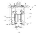
- a motor (100) may be an electric steering motor connected to a steering axis connected to a steering wheel for easy manipulation of a vehicle, for example.
- the motor (100) includes a rotor (120), a rotation shaft (130) and a stator (140).
- the motor (100) may further include a housing (110) and a housing cover (115).
- the housing (110) and the housing cover (115) functions to accommodate the rotor (120) of the motor (100) and the stator (140), and the housing (110) and the housing cover (115) functions to rotatably fix the rotation shaft (130).
- the housing (110) takes a shape of an upper surface-opened cylinder, and the housing (110) may be formed with an upper surface-opened cylinder, for example.
- the housing cover (115) covers an upper surface of the upper-surface opened housing (110).
- a bottom surface of the housing (110) and a center of the housing cover (115) are arranged with bearings (116, 117), and the bearings (116, 117) are coupled by both distal ends of the rotation shaft (130).
- the rotation shaft (130) is rotatably coupled to the housing (110) and the housing cover (115) respectively.
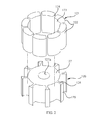
- the rotor (120) includes a plurality of magnets (121) and a rotor core (126).
- the magnet (121) takes a shape of a plate.
- the magnet (121) takes a shape of a flat plate or a curved plate.
- the magnet (121) takes a shape of a curved plate.
- a surface of the magnet opposite to a body (127) of the rotor core (126, described later) is defined as a rear surface (123), a surface opposite to the rear surface (123) is defined as a front surface (122), and a pair of surfaces mutually connecting the rear surface (123) and the front surface (122) is defined as a lateral surface (124).
- the rear surface (123) of the magnet (121) is formed with a curved concave surface, and the rear surface (123) is formed with a curvature substantially same as that of the rotor core (126, described later).
- the front surface (122) of the magnet (121) may be formed with a convex curved surface.
- Each of the pair of lateral surfaces of the magnet (121) is formed with a flat surface.
- a first curved unit (125) is particularly formed between the pair of lateral surfaces (124) and the front surface (122).
- Each first curved unit (125) of the magnet (121) restricts or prevents generation of cracks from the magnet (121) and generation of chips caused by generation of cracks due to vibration and shock applied from outside while the magnet (121) and the rotor core (126, described later) are brought into contact.
- the first curved unit (125) is alternatively formed in a shape of chamfer or a hitching staircase
- a stress is concentrated on an area formed by the rotor core (126, described later) and the magnet (121) or on an area formed by the rotor core (126) and the hitching staircase of the magnet (121) to cause the magnet to easily generate cracks or to generate lots of chips caused by the cracks.
- noise may be generated by the chips generated inside the motor (100) or the rotary force of the motor (100) may be decreased.
- a corner area joined by the lateral surfaces (124) and the front surface (122) of the magnet (121) is formed with a first curved unit (125) to restrict or prevent the generation of cracks and chips on the magnet (121).
- a plurality of circular magnets is arranged on a periphery of the rotor core (126), and in the exemplary embodiment of the present disclosure, a total of eight magnets (121) are formed on the periphery of the rotor core (126), and a gap is formed between each of the magnets (121).
- the rotor core (126) may be formed by stacking a plurality of silicone plates, each having a thin thickness, and an overall look of the rotor core (126) may take a shape of a cylinder.
- the rotor core (126) includes a body (127), a first disengagement prevention unit (128) and a second disengagement prevention unit (129).
- one rotor core (126) is coupled to the rotation shaft (130), for example.
- the body (127), the first disengagement prevention unit (128) and the second disengagement prevention unit (129) may be integrally formed.
- the first and second disengagement prevention units (128, 129) may be integrally formed, and the first disengagement prevention unit (128) and the body (127) may be coupled together in a sliding method.
- the body (127) may take a shape of a cylinder, and the body (127) is centrally formed with a rotation shaft hole (127a) passing through an upper surface of the body (127) and a bottom surface opposite to the upper surface, and the rotation shaft hole (127a) may be coupled to the rotation shaft (130) by way of press-fitting method.
- the first disengagement prevention unit (128) is protruded to a radially external side along a periphery of the body (127).
- the first disengagement prevention unit (128) is protruded from the periphery of the body (127) in a shape of a rib, and protruded between a gap formed by the circularly arranged magnets (121).
- Both lateral surfaces of the first disengagement prevention unit (128) protruded between the pair of magnets (121) are brought into contact with lateral surfaces (124) of the pair of magnets (121) arranged at both sides of the first disengagement prevention unit (128).
- the magnets (121) are prevented from moving relative to the rotor core (126) to additionally prevent generation of cracks of the magnets (121) or destruction caused by the cracks, because each of both the lateral surfaces of the first disengagement prevention unit (128) is brought into contact with each of the lateral surfaces (124) of the magnets (121).
- the second disengagement prevention unit (129) is installed at a distal end of the first disengagement prevention unit (128) to a circumferential direction of the body (127). That is, the second disengagement prevention unit (129) is extended toward the front surface (122) of the pair of magnets (121) arranged at both sides of the first disengagement prevention unit (128), and the second disengagement prevention unit (129) prevents the magnets (121) from being disengaged from the rotor core (126) by pressing the first curved unit (125) of the magnets (121).
- an area extended from the first disengagement prevention unit (128) to the second disengagement prevention unit (129) is formed with a second curved unit (126a) closely contacting the first curved unit (125) of the magnet (121).
- the second curved unit (126a) is formed with a same curvature as that of the first curved unit (125), whereby the first and second curved units (125, 126a) of the magnet (121) are mutually surface-contacted.
- the magnet (121) is securely fixed to the rotor core (126) to restrict or prevent generation of cracks on the magnet (121) and generation of chips caused by the cracks of the brittle magnet (121) due to relative movement of the magnet (121) and the rotor core (126).
- the stator (140) includes a stator core (142) and a coil (144).
- Each of stator cores of the stator core (142) takes a radially protruded shape, the stator core (142) is wound with the coil (144), and the stator core (142) is fixed to an inner surface of the housing (110) by way of press-fitting method.
- the gap formed between the stator (140) and the rotor (120) can be reduced by approximately 20% to approximately 50%.
- FIG. 5 is a partially cut-out cross-sectional perspective view illustrating a motor according to another exemplary embodiment of the present disclosure.
- the motor of FIG. 5 is substantially same as that of FIGS. 1 to 4 in terms of configuration except for the number of rotor cores of the rotor and arrangement thereof.
- like reference numerals are used for like and corresponding parts, and explanations overlapping those in FIGS. 1 to 4 will be omitted.
- the motor (100) includes a rotor (120), a rotation shaft (130) and a stator (140).
- the motor (100) may further include a housing (110) and a housing cover (115).
- At least two, preferably three magnets (121) and at least two, preferably three rotor cores (126) fixed by the magnets (121) may be arranged, and each magnet (121) of the plurality of rotor cores (126) serially coupled to one rotation shaft (130) may be alternatively arranged from the other magnet (121).
- a rotor and a motor having the same can advantageously prevent a magnet of a fast-rotating rotor from being disengaged from a rotor core, noise and decrease in rotary force caused by cracks on the magnet and generation of chips by the cracks caused by vibration and shock applied to the rotor can be prevented and a gap between a stator and the rotor can be reduced.
Landscapes
- Engineering & Computer Science (AREA)
- Power Engineering (AREA)
- Permanent Field Magnets Of Synchronous Machinery (AREA)
- Iron Core Of Rotating Electric Machines (AREA)
Applications Claiming Priority (1)
| Application Number | Priority Date | Filing Date | Title |
|---|---|---|---|
| KR20120067328 | 2012-06-22 |
Publications (1)
| Publication Number | Publication Date |
|---|---|
| EP2677632A2 true EP2677632A2 (de) | 2013-12-25 |
Family
ID=48740861
Family Applications (1)
| Application Number | Title | Priority Date | Filing Date |
|---|---|---|---|
| EP13173110.1A Withdrawn EP2677632A2 (de) | 2012-06-22 | 2013-06-20 | Rotor mit Magneten an der Oberfläche |
Country Status (3)
| Country | Link |
|---|---|
| US (1) | US20130342064A1 (de) |
| EP (1) | EP2677632A2 (de) |
| CN (1) | CN103516082A (de) |
Families Citing this family (5)
| Publication number | Priority date | Publication date | Assignee | Title |
|---|---|---|---|---|
| KR102165612B1 (ko) * | 2014-01-22 | 2020-10-14 | 엘지이노텍 주식회사 | 모터 |
| WO2015118682A1 (ja) * | 2014-02-10 | 2015-08-13 | 三菱電機株式会社 | 回転子 |
| JP5808445B2 (ja) * | 2014-02-21 | 2015-11-10 | ファナック株式会社 | 回転子鉄心の外周面に貼り付けられた磁石を備える電動機の回転子、電動機、及び電動機の回転子の製造方法 |
| US12244182B2 (en) | 2019-12-23 | 2025-03-04 | Lg Innotek Co., Ltd. | Motor |
| KR102836889B1 (ko) * | 2019-12-23 | 2025-07-23 | 엘지이노텍 주식회사 | 모터 |
Family Cites Families (11)
| Publication number | Priority date | Publication date | Assignee | Title |
|---|---|---|---|---|
| US5397951A (en) * | 1991-11-29 | 1995-03-14 | Fanuc Ltd. | Rotor for a synchronous rotary machine |
| WO1998040952A1 (en) * | 1997-03-13 | 1998-09-17 | Matsushita Electric Industrial Co., Ltd. | Rotor core for reluctance motor |
| WO2004093298A1 (ja) * | 2003-04-11 | 2004-10-28 | Mitsubishi Denki Kabushiki Kaisha | 永久磁石式電動機 |
| JP4270942B2 (ja) * | 2003-05-29 | 2009-06-03 | 株式会社日立製作所 | 電動機 |
| JP2005354768A (ja) * | 2004-06-09 | 2005-12-22 | Okuma Corp | 表面磁石型界磁ロータ及びそれを利用したモータ |
| EP1748533B1 (de) * | 2005-07-29 | 2010-09-01 | Siemens Aktiengesellschaft | Permanentmagnetrotor für eine bürstenlose elektrische Maschine |
| JP4836555B2 (ja) * | 2005-11-24 | 2011-12-14 | 株式会社東芝 | 永久磁石型モータ |
| US20070138891A1 (en) * | 2005-12-19 | 2007-06-21 | Emerson Electric Co. | Magnet retention and positioning sleeve for surface mounted rotor assemblies |
| CN101635479A (zh) * | 2008-07-24 | 2010-01-27 | 李明山 | 交流电动机用永磁转子 |
| JP5493675B2 (ja) * | 2009-02-09 | 2014-05-14 | 株式会社ジェイテクト | 電動モータおよびロータ |
| JP6008228B2 (ja) * | 2011-12-26 | 2016-10-19 | 日本電産株式会社 | モータ |
-
2013
- 2013-06-20 EP EP13173110.1A patent/EP2677632A2/de not_active Withdrawn
- 2013-06-20 US US13/922,940 patent/US20130342064A1/en not_active Abandoned
- 2013-06-24 CN CN201310252838.5A patent/CN103516082A/zh active Pending
Non-Patent Citations (1)
| Title |
|---|
| None |
Also Published As
| Publication number | Publication date |
|---|---|
| CN103516082A (zh) | 2014-01-15 |
| US20130342064A1 (en) | 2013-12-26 |
Similar Documents
| Publication | Publication Date | Title |
|---|---|---|
| US10193416B2 (en) | Motor | |
| JP5889576B2 (ja) | ブラシレスモータ | |
| KR101597965B1 (ko) | 복합 자속을 이용한 모터 | |
| US9385567B2 (en) | Rotating electric machine | |
| US20140232232A1 (en) | Rotary electric machine | |
| EP2677632A2 (de) | Rotor mit Magneten an der Oberfläche | |
| US9455602B2 (en) | Motor | |
| US10476325B2 (en) | Inner-rotor motor and rotor thereof | |
| US20080012434A1 (en) | Motor and rotor structure thereof | |
| US20150145367A1 (en) | Permanent magnet rotor | |
| CN108023416A (zh) | 永磁式转子与永磁式转动构件 | |
| US20180209330A1 (en) | Electric supercharger | |
| CN102868243A (zh) | 旋转电机 | |
| US8766502B2 (en) | Rotor having shaft slip inhibition structure and motor having the same | |
| CN103795162A (zh) | 电机及具有该电机的双滚子压缩机 | |
| CN111919361B (zh) | 转子、马达以及电动助力转向装置 | |
| JP2013208014A (ja) | 回転電機 | |
| JP2019030041A (ja) | 回転電機 | |
| CN107925286A (zh) | 旋转电机 | |
| JP2012080607A (ja) | 回転電機のロータ | |
| JP2005312189A (ja) | 回転電機の回転子 | |
| US11005333B2 (en) | Electric motor having a stator with a radially outside rotor with the rotor having a fan mounting portion comprising a noncontact region and a contract region configured to contact a mouting surface of a fan | |
| KR101628961B1 (ko) | 편평형 브러시리스용 회전자 및 그 회전자를 포함한 편평형 브러시리스 모터 | |
| KR20190074467A (ko) | 분할 고정자를 갖는 모터 | |
| JP2014128116A (ja) | 永久磁石埋設型回転電機 |
Legal Events
| Date | Code | Title | Description |
|---|---|---|---|
| PUAI | Public reference made under article 153(3) epc to a published international application that has entered the european phase |
Free format text: ORIGINAL CODE: 0009012 |
|
| AK | Designated contracting states |
Kind code of ref document: A2 Designated state(s): AL AT BE BG CH CY CZ DE DK EE ES FI FR GB GR HR HU IE IS IT LI LT LU LV MC MK MT NL NO PL PT RO RS SE SI SK SM TR |
|
| AX | Request for extension of the european patent |
Extension state: BA ME |
|
| STAA | Information on the status of an ep patent application or granted ep patent |
Free format text: STATUS: THE APPLICATION HAS BEEN PUBLISHED |
|
| RAP1 | Party data changed (applicant data changed or rights of an application transferred) |
Owner name: LG INNOTEK CO., LTD. |
|
| STAA | Information on the status of an ep patent application or granted ep patent |
Free format text: STATUS: THE APPLICATION IS DEEMED TO BE WITHDRAWN |
|
| 18D | Application deemed to be withdrawn |
Effective date: 20170103 |