EP2677687A2 - Appareils électroniques, système et procédé de diagnostic pour appareils électroniques - Google Patents
Appareils électroniques, système et procédé de diagnostic pour appareils électroniques Download PDFInfo
- Publication number
- EP2677687A2 EP2677687A2 EP12747574.7A EP12747574A EP2677687A2 EP 2677687 A2 EP2677687 A2 EP 2677687A2 EP 12747574 A EP12747574 A EP 12747574A EP 2677687 A2 EP2677687 A2 EP 2677687A2
- Authority
- EP
- European Patent Office
- Prior art keywords
- home appliance
- images
- product information
- unit
- diagnosis
- Prior art date
- Legal status (The legal status is an assumption and is not a legal conclusion. Google has not performed a legal analysis and makes no representation as to the accuracy of the status listed.)
- Granted
Links
Images


Classifications
-
- G—PHYSICS
- G06—COMPUTING OR CALCULATING; COUNTING
- G06K—GRAPHICAL DATA READING; PRESENTATION OF DATA; RECORD CARRIERS; HANDLING RECORD CARRIERS
- G06K7/00—Methods or arrangements for sensing record carriers, e.g. for reading patterns
- G06K7/01—Details
-
- H—ELECTRICITY
- H04—ELECTRIC COMMUNICATION TECHNIQUE
- H04L—TRANSMISSION OF DIGITAL INFORMATION, e.g. TELEGRAPHIC COMMUNICATION
- H04L12/00—Data switching networks
- H04L12/28—Data switching networks characterised by path configuration, e.g. LAN [Local Area Networks] or WAN [Wide Area Networks]
- H04L12/2803—Home automation networks
- H04L12/2823—Reporting information sensed by appliance or service execution status of appliance services in a home automation network
- H04L12/2825—Reporting to a device located outside the home and the home network
-
- H—ELECTRICITY
- H04—ELECTRIC COMMUNICATION TECHNIQUE
- H04L—TRANSMISSION OF DIGITAL INFORMATION, e.g. TELEGRAPHIC COMMUNICATION
- H04L12/00—Data switching networks
- H04L12/28—Data switching networks characterised by path configuration, e.g. LAN [Local Area Networks] or WAN [Wide Area Networks]
- H04L12/2803—Home automation networks
- H04L12/2823—Reporting information sensed by appliance or service execution status of appliance services in a home automation network
- H04L12/2827—Reporting to a device within the home network; wherein the reception of the information reported automatically triggers the execution of a home appliance functionality
-
- F—MECHANICAL ENGINEERING; LIGHTING; HEATING; WEAPONS; BLASTING
- F25—REFRIGERATION OR COOLING; COMBINED HEATING AND REFRIGERATION SYSTEMS; HEAT PUMP SYSTEMS; MANUFACTURE OR STORAGE OF ICE; LIQUEFACTION SOLIDIFICATION OF GASES
- F25D—REFRIGERATORS; COLD ROOMS; ICE-BOXES; COOLING OR FREEZING APPARATUS NOT OTHERWISE PROVIDED FOR
- F25D2400/00—General features of, or devices for refrigerators, cold rooms, ice-boxes, or for cooling or freezing apparatus not covered by any other subclass
- F25D2400/36—Visual displays
- F25D2400/361—Interactive visual displays
-
- G—PHYSICS
- G06—COMPUTING OR CALCULATING; COUNTING
- G06Q—INFORMATION AND COMMUNICATION TECHNOLOGY [ICT] SPECIALLY ADAPTED FOR ADMINISTRATIVE, COMMERCIAL, FINANCIAL, MANAGERIAL OR SUPERVISORY PURPOSES; SYSTEMS OR METHODS SPECIALLY ADAPTED FOR ADMINISTRATIVE, COMMERCIAL, FINANCIAL, MANAGERIAL OR SUPERVISORY PURPOSES, NOT OTHERWISE PROVIDED FOR
- G06Q20/00—Payment architectures, schemes or protocols
- G06Q20/30—Payment architectures, schemes or protocols characterised by the use of specific devices or networks
- G06Q20/32—Payment architectures, schemes or protocols characterised by the use of specific devices or networks using wireless devices
- G06Q20/327—Short range or proximity payments by means of M-devices
- G06Q20/3276—Short range or proximity payments by means of M-devices using a pictured code, e.g. barcode or QR-code, being read by the M-device
-
- H—ELECTRICITY
- H04—ELECTRIC COMMUNICATION TECHNIQUE
- H04L—TRANSMISSION OF DIGITAL INFORMATION, e.g. TELEGRAPHIC COMMUNICATION
- H04L41/00—Arrangements for maintenance, administration or management of data switching networks, e.g. of packet switching networks
- H04L41/06—Management of faults, events, alarms or notifications
-
- H—ELECTRICITY
- H04—ELECTRIC COMMUNICATION TECHNIQUE
- H04L—TRANSMISSION OF DIGITAL INFORMATION, e.g. TELEGRAPHIC COMMUNICATION
- H04L43/00—Arrangements for monitoring or testing data switching networks
- H04L43/08—Monitoring or testing based on specific metrics, e.g. QoS, energy consumption or environmental parameters
- H04L43/0805—Monitoring or testing based on specific metrics, e.g. QoS, energy consumption or environmental parameters by checking availability
- H04L43/0817—Monitoring or testing based on specific metrics, e.g. QoS, energy consumption or environmental parameters by checking availability by checking functioning
-
- H—ELECTRICITY
- H04—ELECTRIC COMMUNICATION TECHNIQUE
- H04M—TELEPHONIC COMMUNICATION
- H04M1/00—Substation equipment, e.g. for use by subscribers
- H04M1/26—Devices for calling a subscriber
- H04M1/27—Devices whereby a plurality of signals may be stored simultaneously
- H04M1/274—Devices whereby a plurality of signals may be stored simultaneously with provision for storing more than one subscriber number at a time, e.g. using toothed disc
- H04M1/2745—Devices whereby a plurality of signals may be stored simultaneously with provision for storing more than one subscriber number at a time, e.g. using toothed disc using static electronic memories, e.g. chips
- H04M1/2753—Devices whereby a plurality of signals may be stored simultaneously with provision for storing more than one subscriber number at a time, e.g. using toothed disc using static electronic memories, e.g. chips providing data content
- H04M1/2755—Devices whereby a plurality of signals may be stored simultaneously with provision for storing more than one subscriber number at a time, e.g. using toothed disc using static electronic memories, e.g. chips providing data content by optical scanning
-
- H—ELECTRICITY
- H04—ELECTRIC COMMUNICATION TECHNIQUE
- H04M—TELEPHONIC COMMUNICATION
- H04M2250/00—Details of telephonic subscriber devices
- H04M2250/52—Details of telephonic subscriber devices including functional features of a camera
Definitions
- the present invention concerns a home appliance, a home appliance diagnosing system, and a home appliance diagnosing method. More specifically, the present invention relates to a home appliance outputting product information as a sequence of images, and a home appliance diagnosing system and method that analyzes the sequence of images output from the home appliance to thereby perform diagnosis on the home appliance.
- a home appliance When a home appliance causes an error while in operation, a user sends an inquiry to a service center and the user by himself takes care of erroneous symptoms or requests a service person to visit and handle it.
- the service center may properly respond to it.
- the home appliance configures information to be transferred to the service center in the form of a sound by combining multiple signals with different frequencies, signal conversion takes long, and a user needs to hold on the phone until a signal sound output from the home appliance is completely received, thus causing inconvenience.
- An object of the present invention is to provide a home appliance, a home appliance diagnosing system, and a home appliance diagnosing method that may more precisely transfer product information to a diagnosing server.
- an object of the present invention is to provide a home appliance that may output product information more quickly.
- an object of the present invention is to provide a home appliance that may output product information using a plurality of images sequentially output and that may simply configure a displaying apparatus for outputting the plurality of images.
- an object of the present invention is to provide a home appliance diagnosing system and a home appliance diagnosing method that may prevent service personnel from being unnecessarily dispatched to take care of malfunctions of a home appliance.
- a home appliance includes a selecting unit receiving a diagnosis command; a displaying unit outputting an image; and a controller performing control so that product information is converted into a plurality of images according to the diagnosis command entered to the selecting unit and the plurality of images are sequentially output through the displaying unit.
- a home appliance diagnosing system includes a home appliance converting product information to a plurality of images and sequentially displaying the plurality of images; a terminal sequentially recognizing the plurality of images displayed on the home appliance, extracting the product information from the plurality of recognized images, and transmitting the product information through a network; and a diagnosing server receiving the product information through the network and performing diagnosis on the home appliance based on the product information.
- a home appliance diagnosing method includes step (a) of converting information of a home appliance into a plurality of images according to a diagnosis command entered through a selecting unit; step (b) of sequentially outputting the plurality of images converted in step (a); and step (c) of sequentially recognizing the images output in step (b), extracting the product information from the plurality of images, and performing diagnosis on the home appliance.
- a home appliance, a home appliance diagnosing system, and a home appliance diagnosing method may precisely transfer product information of the home appliance to a service center even without a user specifically explaining erroneous symptoms of the home appliance to a service center.
- the home appliance according to the present invention may output product information as a sequence of images so that time of outputting product information may be reduced in comparison with when the product information is output as a sound. Accordingly, the same amount of product information may be output within a shorter time.
- the home appliance, home appliance diagnosing system and home appliance diagnosing method according to the present invention may precisely transfer product information of the home appliance to a diagnosing server regardless of nose created in the ambient environment where the home appliance is installed.
- the home appliance diagnosing system may increase reliability of product information transmitted to the diagnosing server through a user's terminal.
- Fig. 1 shows a home appliance and a home appliance diagnosing system according to an embodiment of the present invention.
- Fig. 1 illustrates a refrigerator and a washing machine as examples of the home appliance, the home appliance is not limited thereto.
- the home appliance diagnosing system includes a home appliance that converts product information to a plurality of images and sequentially displays the plurality of images, a terminal that recognizes the plurality of images sequentially displayed by the home appliance, extracts the product information from the plurality of recognized images, and transmits the product information through a network, and a diagnosing server that is connected to the network and receives the product information transmitted from the terminal and performs diagnosis on the home appliance.
- the product information may include at least one of operation information, usage information, and failure information of the home appliance.
- the operation information may include configuration information set by a user and information on the operation state of the home appliance.
- the operation information may include temperature configuration information (configuration information) of a refrigerating compartment or freezing compartment as set by a user and a current temperature value (information on the operation state) of the refrigerating compartment or freezing compartment as sensed by a sensing unit.
- the usage information may include identification information for identifying the type of the home appliance and information on an operation history of the home appliance.
- the identification information may be, e.g., information for identifying that a home appliance targeted for diagnosis is a refrigerator
- the operation history information may be, e.g., information regarding patterns in which the refrigerator have been operating within a few recent hours.
- the failure information may include information on malfunctions of the home appliance.
- the failure information may be error codes obtained by estimating whether components of the home appliance cause malfunctions from values sensed by a sensing unit 40.
- a plurality of images (a1 to an) converted from the product information are sequentially output through a displaying unit 20 provided in the home appliance.
- a user recognizes the plurality of images (a1 to an) output through the displaying unit 20 by using a terminal.
- the terminal may be a mobile terminal such as a mobile phone having a video capturing device.
- the mobile terminal may provide a standardized interface and flat form for application developers so as to perform such functions as PC (Personal Computers) as well as calling functions.
- an application for inversely extracting the product information from the images recognized by the video capturing device.
- the images recognized by the capturing device may be transmitted through a network.
- the product information may be inversely extracted from the images through the application, and the extracted product information may be transmitted through a network.
- the diagnosing server is connected to the network and receives data transmitted through the network and diagnoses the state of the home appliance.
- the network may be, e.g., a mobile telecommunication network based on FDMA (Frequency Division Multiple Access), GSM (Global System for Mobile Communications), CDMA (Code Division Multiple Access), W-CDMA (Wideband Code Division Multiple Access), or CDMA 2000, wired Internet or wireless Internet such as Wi-Fi enabling wireless communication between devices through a wireless LAN.
- FDMA Frequency Division Multiple Access
- GSM Global System for Mobile Communications
- CDMA Code Division Multiple Access
- W-CDMA Wideband Code Division Multiple Access
- CDMA 2000 Code Division Multiple Access
- wired Internet or wireless Internet such as Wi-Fi enabling wireless communication between devices through a wireless LAN.
- the diagnosing server directly receives the product information from the terminal through the network and performs diagnosis on the home appliance based on the product information.
- Such scheme may be applicable to a terminal that may have an image capturing function and may drive an application inversely extracting product information from a captured image.
- the diagnosing server may include a communication unit that receives product information transmitted from the terminal through the network, a diagnosis data storing unit that stores diagnosis data, and a diagnosing unit that performs diagnosis on the home appliance by comparing the product information received through the communication unit with the diagnosis data stored in the diagnosis data storing unit.
- the diagnosing unit inversely extracts the product information from the data transmitted from the communication unit through the network and performs diagnosis on the home appliance based on the extracted product information.
- Such scheme enables the home appliance to be diagnosed by a terminal that has functions of capturing images, making captured images as data and transferring the data through the network but that cannot drive an application for inversely extracting the product information from the captured images.
- the diagnosing server may further include a diagnosis result displaying unit that outputs a diagnosis result of the home appliance as analyzed by the diagnosing unit to be recognized by stand-by personnel in the service center.
- the communication unit of the diagnosing server may be configured to transmit a diagnosis result obtained by the diagnosing unit of the diagnosing server to the terminal through a communication network as well as to receive data transmitted from the terminal, and in such case, a user may immediately recognize the diagnosis result through the terminal.
- Fig. 2 is a block diagram illustrating main components of a home appliance according to an embodiment of the present invention.
- Fig. 3 shows an example of the displaying unit shown in Fig. 2 .
- the home appliance includes a selecting unit 10 for receiving a predetermined diagnosis command from a user, a displaying unit 20 for outputting an image, and a controller 30 for converting product information to a plurality of images according to the diagnosis command entered to the selecting unit 10 and for performing control to enable the plurality of images to be sequentially output through the displaying unit 20.
- the controller 30 performs control so that an operation being currently underway is paused or terminated and enters into a diagnosis mode, the product information is split into a plurality of unit data, each split unit data is encoded into a predetermined control signal, and the selecting unit 10 may sequentially output images respectively corresponding to the unit data depending on the control signal.
- a displaying unit 120 which is an example of the displaying unit 20 shown in Fig. 2 , may include a plurality of light emission members 121 that emit light in a predetermined pattern according to the control signal from the controller 30.
- Fig. 1 shows an example where a plurality of images a1 to an are sequentially output according to the light emission pattern of the plurality of light emission members 121.
- Each of image a1 to an respectively corresponds to each of unit data split from the product information and may be output at a predetermined time interval.
- reference 121a denotes a light-off light emission member
- reference 121b denotes a light-on light emission member.
- the displaying unit 120 has the plurality of light emission members 121 arranged vertically/horizontally in a grid pattern.
- the shape of an image displayed varies depending on the pattern in which the plurality of light emission members 121 emit light.
- the light emission members 121 may be LEDs (Light Emitting Diodes).
- the displaying unit 120 may include a positioning marking unit 122.
- the positioning marking unit 122 marks a position where an image is recognized which is formed according to the light emitting pattern of the light emission members 121. In other words, a position which functions as a standard when an image displayed on the displaying unit 120 is read is marked.
- images captured by the terminal is analyzed by an application, the images may be arranged with respect to the positioning marking unit 122, thereby providing exact information.
- a sensing unit 40 senses the operation state of the home appliance.
- the sensing unit 40 may sense operation information of various devices constituting the home appliance and state information such as temperature, moisture, dryness, power consumption, and electric conductivity which need to be sensed to control the devices.
- a memory 50 may store control data of the home appliance and product information constituted of operation information of the home appliance, usage information and/or failure information.
- the controller 30 may control the overall operation of the home appliance according to the control data stored in the memory 50, and upon diagnosis, may perform control so that the product information stored in the memory 50 is called out and split into a plurality of unit data, each split unit data is encoded into a predetermined control signal, and the displaying unit 120 sequentially outputs images corresponding to each unit data depending on the control signal.
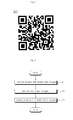
- Fig. 4 shows another example of the displaying unit shown in Fig. 2 .
- the displaying unit 220 may sequentially output a sequence of QR (Quick Response) codes including product information according to a control signal of the controller 30.
- the QR codes are matrix-like two-dimensional bar codes that represent information in a lattice pattern.
- the displaying unit 220 may include an LED panel to display the QR codes.
- Fig. 5 is a flowchart illustrating a home appliance diagnosing method according to an embodiment of the present invention.
- the home appliance displaying area includes a step S1 of converting product information of a home appliance to a plurality of images according to a diagnosis command entered through the selecting unit 10, a step S2 of sequentially outputting the plurality of converted images, and a step S3 of sequentially recognizing the output images, extracting the product information from the recognized images, and performing diagnosis on the home appliance.
- Steps S1 and S2 are performed by the home appliance.
- the controller 30 performs control so that the operation currently underway is paused or terminated and enters into a diagnosis mode, the product information is split into a plurality of unit data, each split unit data is encoded into a predetermined control signal, and the displaying unit 20 sequentially outputs images corresponding to each unit data according to the control signal.
- step S3 extracting the product information from a sequence of images output from the home appliance is conducted by the terminal or the diagnosing server.
- the sequence of images including the product information output from the home appliance is recognized through a video capturing device provided in the terminal, but inversely extracting the product information from the images recognized through the video capturing device may be carried out by either the terminal or the diagnosing server.
- the terminal transmits the extracted product information to the diagnosing server through the network, and the diagnosing server performs diagnosis on the home appliance by analyzing the received product information.
- the diagnosing server inversely extracts the product information from the image data transmitted through the network and diagnoses the home appliance through the extracted product information.
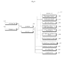
- Fig. 6 shows main components of a refrigerator as an example of a home appliance according to an embodiment of the present invention.
- the refrigerator an example of a home appliance according to the present invention, may include a selecting unit 610, a displaying unit 620, a controller 630, a sensing unit 640, and a memory 650.
- the selecting unit 610, the displaying unit 620, the controller 630, the sensing unit 640, and the memory 650 are denoted with reference numerals different from the selecting unit 10, the displaying unit 20, the controller 30, the sensing unit 40, and the memory 50, respectively, as described above in connection with Fig.
- Fig. 2 for the purpose of being recognized as components of the refrigerator that is an example of the home appliance according to the present invention, but the description on the components shown in Fig. 2 may apply thereto.
- various examples of the sensing unit 640 are specifically illustrated in Fig. 6 .
- the refrigerator may include a refrigerating compartment and a freezing compartment, a refrigerating compartment fan 661 for blowing cold air to the refrigerating compartment, a freezing compartment fan 662 for blowing cold air to the freezing compartment, a defrosting heater 663 provided when the refrigerator has a food defrosting function, and a condenser fan 664 for dissipating heat generated from a condenser condensing a coolant.
- the sensing unit 640 may include a refrigerating compartment temperature sensor 641 sensing the temperature of the refrigerating compartment, a freezing compartment temperature sensor 642 sensing the temperature of the freezing compartment, a defrosting sensor 643 sensing frost generated on the surface of an evaporator to determine whether a defrosting operation is performed, a refrigerating compartment fan motor sensor 644 sensing whether the refrigerating compartment fan 661 normally operates, and/or a freezing compartment fan motor sensor 645 sensing whether the freezing compartment fan 662 normally operates.
- a refrigerating compartment temperature sensor 641 sensing the temperature of the refrigerating compartment
- a freezing compartment temperature sensor 642 sensing the temperature of the freezing compartment
- a defrosting sensor 643 sensing frost generated on the surface of an evaporator to determine whether a defrosting operation is performed
- a refrigerating compartment fan motor sensor 644 sensing whether the refrigerating compartment fan 661 normally operates
- a freezing compartment fan motor sensor 645 sensing whether the freezing
- the ice maker may include a water path through which water necessary to make ice flows and an ice tray in which water coming through the water path is gathered and turns into ice in a predetermined shape.
- the sensing unit 640 may further include an ice maker path temperature sensor 646 measuring the temperature of water in the water path and an ice tray temperature sensor 647 measuring the temperature in the ice tray.
- the images output through the displaying unit 620 of the refrigerator may include information (operation information) on values sensed by the sensing unit 641 to 647 and malfunction information (failure information) obtained based on the sensed values.
Landscapes
- Engineering & Computer Science (AREA)
- Automation & Control Theory (AREA)
- Computer Networks & Wireless Communication (AREA)
- Signal Processing (AREA)
- Physics & Mathematics (AREA)
- Theoretical Computer Science (AREA)
- General Physics & Mathematics (AREA)
- Artificial Intelligence (AREA)
- Computer Vision & Pattern Recognition (AREA)
- Business, Economics & Management (AREA)
- Strategic Management (AREA)
- General Business, Economics & Management (AREA)
- Accounting & Taxation (AREA)
- Environmental & Geological Engineering (AREA)
- Telephonic Communication Services (AREA)
- Selective Calling Equipment (AREA)
- Management, Administration, Business Operations System, And Electronic Commerce (AREA)
- Testing, Inspecting, Measuring Of Stereoscopic Televisions And Televisions (AREA)
Applications Claiming Priority (2)
| Application Number | Priority Date | Filing Date | Title |
|---|---|---|---|
| KR1020110012876A KR101772543B1 (ko) | 2011-02-14 | 2011-02-14 | 가전기기, 가전기기 진단시스템 및 가전기기 진단방법 |
| PCT/KR2012/001040 WO2012111945A2 (fr) | 2011-02-14 | 2012-02-13 | Appareils électroniques, système et procédé de diagnostic pour appareils électroniques |
Publications (3)
| Publication Number | Publication Date |
|---|---|
| EP2677687A2 true EP2677687A2 (fr) | 2013-12-25 |
| EP2677687A4 EP2677687A4 (fr) | 2014-06-11 |
| EP2677687B1 EP2677687B1 (fr) | 2015-07-22 |
Family
ID=46673022
Family Applications (1)
| Application Number | Title | Priority Date | Filing Date |
|---|---|---|---|
| EP12747574.7A Not-in-force EP2677687B1 (fr) | 2011-02-14 | 2012-02-13 | Appareils électroniques, système et procédé de diagnostic pour appareils électroniques |
Country Status (6)
| Country | Link |
|---|---|
| US (1) | US20140085056A1 (fr) |
| EP (1) | EP2677687B1 (fr) |
| KR (1) | KR101772543B1 (fr) |
| CN (1) | CN103229455B (fr) |
| AU (1) | AU2012218285B2 (fr) |
| WO (1) | WO2012111945A2 (fr) |
Cited By (3)
| Publication number | Priority date | Publication date | Assignee | Title |
|---|---|---|---|---|
| WO2015136285A1 (fr) * | 2014-03-11 | 2015-09-17 | British Gas Trading Limited | Détermination de l'état de fonctionnement d'un appareil électroménager |
| EP3067761A1 (fr) * | 2015-03-10 | 2016-09-14 | Stiebel Eltron GmbH & Co. KG | Procede d'analyse et de resolution d'erreurs dans un appareil domotique et systeme domotique |
| EP2618230A3 (fr) * | 2012-01-17 | 2017-05-17 | Lg Electronics Inc. | Appareil ménager, appareil et procédé de diagnostic |
Families Citing this family (8)
| Publication number | Priority date | Publication date | Assignee | Title |
|---|---|---|---|---|
| JP6239906B2 (ja) * | 2012-09-19 | 2017-11-29 | パナソニック インテレクチュアル プロパティ コーポレーション オブ アメリカPanasonic Intellectual Property Corporation of America | アクセス制御方法、アクセス制御システム、通信端末、及び、サーバ |
| CN104678991A (zh) * | 2014-12-26 | 2015-06-03 | 广东美的厨房电器制造有限公司 | 家用电器异常诊断方法及系统、服务器和家用电器 |
| CN109323526A (zh) * | 2017-07-31 | 2019-02-12 | 合肥美的智能科技有限公司 | 智能冰箱报障方法、装置以及冰箱 |
| US10338577B2 (en) * | 2017-08-30 | 2019-07-02 | Cubic Corporation | Sensor-based automated transit maintenance system |
| WO2019139458A2 (fr) * | 2019-01-22 | 2019-07-18 | 엘지전자 주식회사 | Appareil d'intelligence artificielle |
| KR102887151B1 (ko) * | 2019-01-23 | 2025-11-17 | 삼성전자주식회사 | 서버, 단말 장치 및 이의 가전기기 관리 방법 |
| US12205265B2 (en) | 2019-07-11 | 2025-01-21 | Lg Electronics Inc. | Artificial intelligence server |
| US12106176B2 (en) * | 2021-07-19 | 2024-10-01 | EMC IP Holding Company LLC | True secure airgap |
Family Cites Families (11)
| Publication number | Priority date | Publication date | Assignee | Title |
|---|---|---|---|---|
| EP1257978A1 (fr) * | 2000-02-02 | 2002-11-20 | Image Reaction Limited | Manipulation de donnees |
| KR20010104586A (ko) * | 2000-05-15 | 2001-11-26 | 정선구 | 인터넷망을 이용한 기기 고장 진단 장치 |
| TW593950B (en) * | 2000-09-11 | 2004-06-21 | Toshiba Corp | Remote inspection system for refrigerator |
| KR100511950B1 (ko) * | 2002-03-20 | 2005-09-02 | 엘지전자 주식회사 | 네트워크 가능한 가전기기의 이상여부 체크시스템 및 그체크방법 |
| US20100081375A1 (en) * | 2008-09-30 | 2010-04-01 | Apple Inc. | System and method for simplified control of electronic devices |
| US8935187B2 (en) * | 2007-03-07 | 2015-01-13 | Playspan, Inc. | Distributed payment system and method |
| KR101404104B1 (ko) * | 2008-04-30 | 2014-06-10 | 엘지전자 주식회사 | 가전기기 진단시스템 및 그 동작방법 |
| US20100053339A1 (en) * | 2008-09-02 | 2010-03-04 | Erik Aaron | Diagnostic error code |
| KR101579481B1 (ko) * | 2009-04-10 | 2015-12-22 | 엘지전자 주식회사 | 가전기기 진단시스템 및 그 진단방법 |
| US9195898B2 (en) * | 2009-04-14 | 2015-11-24 | Qualcomm Incorporated | Systems and methods for image recognition using mobile devices |
| US9792612B2 (en) * | 2010-11-23 | 2017-10-17 | Echostar Technologies L.L.C. | Facilitating user support of electronic devices using dynamic matrix code generation |
-
2011
- 2011-02-14 KR KR1020110012876A patent/KR101772543B1/ko active Active
-
2012
- 2012-02-13 EP EP12747574.7A patent/EP2677687B1/fr not_active Not-in-force
- 2012-02-13 WO PCT/KR2012/001040 patent/WO2012111945A2/fr not_active Ceased
- 2012-02-13 CN CN201280003943.9A patent/CN103229455B/zh active Active
- 2012-02-13 US US13/884,517 patent/US20140085056A1/en not_active Abandoned
- 2012-02-13 AU AU2012218285A patent/AU2012218285B2/en not_active Ceased
Cited By (4)
| Publication number | Priority date | Publication date | Assignee | Title |
|---|---|---|---|---|
| EP2618230A3 (fr) * | 2012-01-17 | 2017-05-17 | Lg Electronics Inc. | Appareil ménager, appareil et procédé de diagnostic |
| WO2015136285A1 (fr) * | 2014-03-11 | 2015-09-17 | British Gas Trading Limited | Détermination de l'état de fonctionnement d'un appareil électroménager |
| US10218532B2 (en) | 2014-03-11 | 2019-02-26 | British Gas Trading Limited | Determination of a state of operation of a domestic appliance |
| EP3067761A1 (fr) * | 2015-03-10 | 2016-09-14 | Stiebel Eltron GmbH & Co. KG | Procede d'analyse et de resolution d'erreurs dans un appareil domotique et systeme domotique |
Also Published As
| Publication number | Publication date |
|---|---|
| AU2012218285B2 (en) | 2015-05-28 |
| US20140085056A1 (en) | 2014-03-27 |
| WO2012111945A2 (fr) | 2012-08-23 |
| EP2677687B1 (fr) | 2015-07-22 |
| KR20120092937A (ko) | 2012-08-22 |
| CN103229455B (zh) | 2016-05-04 |
| CN103229455A (zh) | 2013-07-31 |
| WO2012111945A3 (fr) | 2012-12-13 |
| EP2677687A4 (fr) | 2014-06-11 |
| AU2012218285A1 (en) | 2013-09-26 |
| KR101772543B1 (ko) | 2017-08-29 |
Similar Documents
| Publication | Publication Date | Title |
|---|---|---|
| AU2012218285B2 (en) | Electronic appliances, diagnostic system for electronic appliances and diagnostic method for electronic appliances | |
| US9383746B2 (en) | Self-diagnosis system of home appliance and operation method of the same | |
| CN103207597B (zh) | 家用电器、诊断设备及方法 | |
| KR102511522B1 (ko) | 데이터 학습 서버, 이의 학습 모델 생성 및 이용 방법 | |
| US10107849B2 (en) | Diagnostic system for a home appliance and method for diagnosing a home appliance | |
| US20160334127A1 (en) | Method and system for proactively and remotely diagnosing an hvac system | |
| CN102654551A (zh) | 故障检测装置、电器以及故障检测方法 | |
| CN110647894B (zh) | 电器设备的故障诊断方法、系统、云端服务器及存储介质 | |
| CN111595081B (zh) | 维护检修方法、维护检修系统和信息终端 | |
| US20130297785A1 (en) | User status analyzing method and apparatus using activity history | |
| US20180218242A1 (en) | Information processing apparatus, information processing method, and computer-readable storage medium | |
| US10254921B2 (en) | Method of controlling mobile terminal | |
| US20170005825A1 (en) | Method and device for event notification in home network system | |
| WO2018071214A1 (fr) | Détermination de l'emplacement physique d'un dispositif de terrain | |
| CN109312948A (zh) | 用于制冷、hvac和其他建筑系统的基于位置的信息检索、查看和诊断 | |
| KR20230026273A (ko) | 환경 센서를 커미셔닝하기 위한 방법 및 시스템 | |
| CN104748504B (zh) | 智能冰箱 | |
| KR20150087039A (ko) | 자가 진단기능을 탑재한 네트워크 카메라 시스템 및 이를 이용한 네트워크 카메라 자가 진단 방법 | |
| WO2018216115A1 (fr) | Système de climatisation | |
| KR101958068B1 (ko) | 스마트 홈 오토메이션 서비스 방법 및 이를 수행하는 장치들 | |
| JP2023150955A (ja) | 情報処理装置、プログラム、および位置検知システム | |
| KR20190068160A (ko) | 인터넷 미설치 편의점의 앱 기반 부대시설 점검시스템 | |
| JP6169408B2 (ja) | 測定装置 | |
| WO2018063104A1 (fr) | Système pour surveiller et alerter un utilisateur d'un dysfonctionnement de climatiseur par un fournisseur de services |
Legal Events
| Date | Code | Title | Description |
|---|---|---|---|
| PUAI | Public reference made under article 153(3) epc to a published international application that has entered the european phase |
Free format text: ORIGINAL CODE: 0009012 |
|
| 17P | Request for examination filed |
Effective date: 20130515 |
|
| AK | Designated contracting states |
Kind code of ref document: A2 Designated state(s): AL AT BE BG CH CY CZ DE DK EE ES FI FR GB GR HR HU IE IS IT LI LT LU LV MC MK MT NL NO PL PT RO RS SE SI SK SM TR |
|
| REG | Reference to a national code |
Ref country code: DE Ref legal event code: R079 Ref document number: 602012009000 Country of ref document: DE Free format text: PREVIOUS MAIN CLASS: H04L0012160000 Ipc: G06Q0020320000 |
|
| DAX | Request for extension of the european patent (deleted) | ||
| A4 | Supplementary search report drawn up and despatched |
Effective date: 20140514 |
|
| RIC1 | Information provided on ipc code assigned before grant |
Ipc: G06Q 20/32 20120101AFI20140508BHEP Ipc: H04M 11/00 20060101ALI20140508BHEP Ipc: H04L 12/28 20060101ALI20140508BHEP |
|
| GRAJ | Information related to disapproval of communication of intention to grant by the applicant or resumption of examination proceedings by the epo deleted |
Free format text: ORIGINAL CODE: EPIDOSDIGR1 |
|
| GRAP | Despatch of communication of intention to grant a patent |
Free format text: ORIGINAL CODE: EPIDOSNIGR1 |
|
| INTG | Intention to grant announced |
Effective date: 20150220 |
|
| RAP1 | Party data changed (applicant data changed or rights of an application transferred) |
Owner name: LG ELECTRONICS INC. |
|
| GRAS | Grant fee paid |
Free format text: ORIGINAL CODE: EPIDOSNIGR3 |
|
| GRAA | (expected) grant |
Free format text: ORIGINAL CODE: 0009210 |
|
| AK | Designated contracting states |
Kind code of ref document: B1 Designated state(s): AL AT BE BG CH CY CZ DE DK EE ES FI FR GB GR HR HU IE IS IT LI LT LU LV MC MK MT NL NO PL PT RO RS SE SI SK SM TR |
|
| REG | Reference to a national code |
Ref country code: GB Ref legal event code: FG4D |
|
| REG | Reference to a national code |
Ref country code: CH Ref legal event code: EP |
|
| REG | Reference to a national code |
Ref country code: IE Ref legal event code: FG4D |
|
| REG | Reference to a national code |
Ref country code: AT Ref legal event code: REF Ref document number: 738280 Country of ref document: AT Kind code of ref document: T Effective date: 20150815 |
|
| REG | Reference to a national code |
Ref country code: DE Ref legal event code: R096 Ref document number: 602012009000 Country of ref document: DE |
|
| REG | Reference to a national code |
Ref country code: AT Ref legal event code: MK05 Ref document number: 738280 Country of ref document: AT Kind code of ref document: T Effective date: 20150722 |
|
| REG | Reference to a national code |
Ref country code: LT Ref legal event code: MG4D |
|
| REG | Reference to a national code |
Ref country code: NL Ref legal event code: MP Effective date: 20150722 |
|
| REG | Reference to a national code |
Ref country code: FR Ref legal event code: PLFP Year of fee payment: 5 |
|
| PG25 | Lapsed in a contracting state [announced via postgrant information from national office to epo] |
Ref country code: LT Free format text: LAPSE BECAUSE OF FAILURE TO SUBMIT A TRANSLATION OF THE DESCRIPTION OR TO PAY THE FEE WITHIN THE PRESCRIBED TIME-LIMIT Effective date: 20150722 Ref country code: LV Free format text: LAPSE BECAUSE OF FAILURE TO SUBMIT A TRANSLATION OF THE DESCRIPTION OR TO PAY THE FEE WITHIN THE PRESCRIBED TIME-LIMIT Effective date: 20150722 Ref country code: GR Free format text: LAPSE BECAUSE OF FAILURE TO SUBMIT A TRANSLATION OF THE DESCRIPTION OR TO PAY THE FEE WITHIN THE PRESCRIBED TIME-LIMIT Effective date: 20151023 Ref country code: FI Free format text: LAPSE BECAUSE OF FAILURE TO SUBMIT A TRANSLATION OF THE DESCRIPTION OR TO PAY THE FEE WITHIN THE PRESCRIBED TIME-LIMIT Effective date: 20150722 Ref country code: NO Free format text: LAPSE BECAUSE OF FAILURE TO SUBMIT A TRANSLATION OF THE DESCRIPTION OR TO PAY THE FEE WITHIN THE PRESCRIBED TIME-LIMIT Effective date: 20151022 |
|
| PG25 | Lapsed in a contracting state [announced via postgrant information from national office to epo] |
Ref country code: IS Free format text: LAPSE BECAUSE OF FAILURE TO SUBMIT A TRANSLATION OF THE DESCRIPTION OR TO PAY THE FEE WITHIN THE PRESCRIBED TIME-LIMIT Effective date: 20151122 Ref country code: RS Free format text: LAPSE BECAUSE OF FAILURE TO SUBMIT A TRANSLATION OF THE DESCRIPTION OR TO PAY THE FEE WITHIN THE PRESCRIBED TIME-LIMIT Effective date: 20150722 Ref country code: AT Free format text: LAPSE BECAUSE OF FAILURE TO SUBMIT A TRANSLATION OF THE DESCRIPTION OR TO PAY THE FEE WITHIN THE PRESCRIBED TIME-LIMIT Effective date: 20150722 Ref country code: ES Free format text: LAPSE BECAUSE OF FAILURE TO SUBMIT A TRANSLATION OF THE DESCRIPTION OR TO PAY THE FEE WITHIN THE PRESCRIBED TIME-LIMIT Effective date: 20150722 Ref country code: SE Free format text: LAPSE BECAUSE OF FAILURE TO SUBMIT A TRANSLATION OF THE DESCRIPTION OR TO PAY THE FEE WITHIN THE PRESCRIBED TIME-LIMIT Effective date: 20150722 Ref country code: HR Free format text: LAPSE BECAUSE OF FAILURE TO SUBMIT A TRANSLATION OF THE DESCRIPTION OR TO PAY THE FEE WITHIN THE PRESCRIBED TIME-LIMIT Effective date: 20150722 Ref country code: PT Free format text: LAPSE BECAUSE OF FAILURE TO SUBMIT A TRANSLATION OF THE DESCRIPTION OR TO PAY THE FEE WITHIN THE PRESCRIBED TIME-LIMIT Effective date: 20151123 Ref country code: PL Free format text: LAPSE BECAUSE OF FAILURE TO SUBMIT A TRANSLATION OF THE DESCRIPTION OR TO PAY THE FEE WITHIN THE PRESCRIBED TIME-LIMIT Effective date: 20150722 |
|
| REG | Reference to a national code |
Ref country code: DE Ref legal event code: R097 Ref document number: 602012009000 Country of ref document: DE |
|
| PG25 | Lapsed in a contracting state [announced via postgrant information from national office to epo] |
Ref country code: IT Free format text: LAPSE BECAUSE OF FAILURE TO SUBMIT A TRANSLATION OF THE DESCRIPTION OR TO PAY THE FEE WITHIN THE PRESCRIBED TIME-LIMIT Effective date: 20150722 Ref country code: SK Free format text: LAPSE BECAUSE OF FAILURE TO SUBMIT A TRANSLATION OF THE DESCRIPTION OR TO PAY THE FEE WITHIN THE PRESCRIBED TIME-LIMIT Effective date: 20150722 Ref country code: EE Free format text: LAPSE BECAUSE OF FAILURE TO SUBMIT A TRANSLATION OF THE DESCRIPTION OR TO PAY THE FEE WITHIN THE PRESCRIBED TIME-LIMIT Effective date: 20150722 Ref country code: DK Free format text: LAPSE BECAUSE OF FAILURE TO SUBMIT A TRANSLATION OF THE DESCRIPTION OR TO PAY THE FEE WITHIN THE PRESCRIBED TIME-LIMIT Effective date: 20150722 Ref country code: CZ Free format text: LAPSE BECAUSE OF FAILURE TO SUBMIT A TRANSLATION OF THE DESCRIPTION OR TO PAY THE FEE WITHIN THE PRESCRIBED TIME-LIMIT Effective date: 20150722 |
|
| PLBE | No opposition filed within time limit |
Free format text: ORIGINAL CODE: 0009261 |
|
| STAA | Information on the status of an ep patent application or granted ep patent |
Free format text: STATUS: NO OPPOSITION FILED WITHIN TIME LIMIT |
|
| PG25 | Lapsed in a contracting state [announced via postgrant information from national office to epo] |
Ref country code: BE Free format text: LAPSE BECAUSE OF NON-PAYMENT OF DUE FEES Effective date: 20160229 Ref country code: RO Free format text: LAPSE BECAUSE OF FAILURE TO SUBMIT A TRANSLATION OF THE DESCRIPTION OR TO PAY THE FEE WITHIN THE PRESCRIBED TIME-LIMIT Effective date: 20150722 |
|
| 26N | No opposition filed |
Effective date: 20160425 |
|
| PG25 | Lapsed in a contracting state [announced via postgrant information from national office to epo] |
Ref country code: SI Free format text: LAPSE BECAUSE OF FAILURE TO SUBMIT A TRANSLATION OF THE DESCRIPTION OR TO PAY THE FEE WITHIN THE PRESCRIBED TIME-LIMIT Effective date: 20150722 |
|
| PG25 | Lapsed in a contracting state [announced via postgrant information from national office to epo] |
Ref country code: MC Free format text: LAPSE BECAUSE OF FAILURE TO SUBMIT A TRANSLATION OF THE DESCRIPTION OR TO PAY THE FEE WITHIN THE PRESCRIBED TIME-LIMIT Effective date: 20150722 Ref country code: LU Free format text: LAPSE BECAUSE OF FAILURE TO SUBMIT A TRANSLATION OF THE DESCRIPTION OR TO PAY THE FEE WITHIN THE PRESCRIBED TIME-LIMIT Effective date: 20160213 |
|
| REG | Reference to a national code |
Ref country code: CH Ref legal event code: PL |
|
| PG25 | Lapsed in a contracting state [announced via postgrant information from national office to epo] |
Ref country code: LI Free format text: LAPSE BECAUSE OF NON-PAYMENT OF DUE FEES Effective date: 20160229 Ref country code: CH Free format text: LAPSE BECAUSE OF NON-PAYMENT OF DUE FEES Effective date: 20160229 |
|
| REG | Reference to a national code |
Ref country code: IE Ref legal event code: MM4A |
|
| PG25 | Lapsed in a contracting state [announced via postgrant information from national office to epo] |
Ref country code: BE Free format text: LAPSE BECAUSE OF FAILURE TO SUBMIT A TRANSLATION OF THE DESCRIPTION OR TO PAY THE FEE WITHIN THE PRESCRIBED TIME-LIMIT Effective date: 20150722 |
|
| REG | Reference to a national code |
Ref country code: FR Ref legal event code: PLFP Year of fee payment: 6 |
|
| PG25 | Lapsed in a contracting state [announced via postgrant information from national office to epo] |
Ref country code: IE Free format text: LAPSE BECAUSE OF NON-PAYMENT OF DUE FEES Effective date: 20160213 |
|
| PG25 | Lapsed in a contracting state [announced via postgrant information from national office to epo] |
Ref country code: NL Free format text: LAPSE BECAUSE OF FAILURE TO SUBMIT A TRANSLATION OF THE DESCRIPTION OR TO PAY THE FEE WITHIN THE PRESCRIBED TIME-LIMIT Effective date: 20150722 |
|
| PG25 | Lapsed in a contracting state [announced via postgrant information from national office to epo] |
Ref country code: MT Free format text: LAPSE BECAUSE OF FAILURE TO SUBMIT A TRANSLATION OF THE DESCRIPTION OR TO PAY THE FEE WITHIN THE PRESCRIBED TIME-LIMIT Effective date: 20150722 |
|
| REG | Reference to a national code |
Ref country code: FR Ref legal event code: PLFP Year of fee payment: 7 |
|
| PG25 | Lapsed in a contracting state [announced via postgrant information from national office to epo] |
Ref country code: CY Free format text: LAPSE BECAUSE OF FAILURE TO SUBMIT A TRANSLATION OF THE DESCRIPTION OR TO PAY THE FEE WITHIN THE PRESCRIBED TIME-LIMIT Effective date: 20150722 Ref country code: SM Free format text: LAPSE BECAUSE OF FAILURE TO SUBMIT A TRANSLATION OF THE DESCRIPTION OR TO PAY THE FEE WITHIN THE PRESCRIBED TIME-LIMIT Effective date: 20150722 Ref country code: HU Free format text: LAPSE BECAUSE OF FAILURE TO SUBMIT A TRANSLATION OF THE DESCRIPTION OR TO PAY THE FEE WITHIN THE PRESCRIBED TIME-LIMIT; INVALID AB INITIO Effective date: 20120213 |
|
| PG25 | Lapsed in a contracting state [announced via postgrant information from national office to epo] |
Ref country code: MK Free format text: LAPSE BECAUSE OF FAILURE TO SUBMIT A TRANSLATION OF THE DESCRIPTION OR TO PAY THE FEE WITHIN THE PRESCRIBED TIME-LIMIT Effective date: 20150722 Ref country code: TR Free format text: LAPSE BECAUSE OF FAILURE TO SUBMIT A TRANSLATION OF THE DESCRIPTION OR TO PAY THE FEE WITHIN THE PRESCRIBED TIME-LIMIT Effective date: 20150722 Ref country code: MT Free format text: LAPSE BECAUSE OF FAILURE TO SUBMIT A TRANSLATION OF THE DESCRIPTION OR TO PAY THE FEE WITHIN THE PRESCRIBED TIME-LIMIT Effective date: 20160229 |
|
| PG25 | Lapsed in a contracting state [announced via postgrant information from national office to epo] |
Ref country code: BG Free format text: LAPSE BECAUSE OF FAILURE TO SUBMIT A TRANSLATION OF THE DESCRIPTION OR TO PAY THE FEE WITHIN THE PRESCRIBED TIME-LIMIT Effective date: 20150722 |
|
| PG25 | Lapsed in a contracting state [announced via postgrant information from national office to epo] |
Ref country code: AL Free format text: LAPSE BECAUSE OF FAILURE TO SUBMIT A TRANSLATION OF THE DESCRIPTION OR TO PAY THE FEE WITHIN THE PRESCRIBED TIME-LIMIT Effective date: 20150722 |
|
| PGFP | Annual fee paid to national office [announced via postgrant information from national office to epo] |
Ref country code: FR Payment date: 20230105 Year of fee payment: 12 |
|
| PGFP | Annual fee paid to national office [announced via postgrant information from national office to epo] |
Ref country code: GB Payment date: 20230105 Year of fee payment: 12 Ref country code: DE Payment date: 20230105 Year of fee payment: 12 |
|
| REG | Reference to a national code |
Ref country code: DE Ref legal event code: R119 Ref document number: 602012009000 Country of ref document: DE |
|
| GBPC | Gb: european patent ceased through non-payment of renewal fee |
Effective date: 20240213 |
|
| PG25 | Lapsed in a contracting state [announced via postgrant information from national office to epo] |
Ref country code: DE Free format text: LAPSE BECAUSE OF NON-PAYMENT OF DUE FEES Effective date: 20240903 |
|
| PG25 | Lapsed in a contracting state [announced via postgrant information from national office to epo] |
Ref country code: GB Free format text: LAPSE BECAUSE OF NON-PAYMENT OF DUE FEES Effective date: 20240213 |
|
| PG25 | Lapsed in a contracting state [announced via postgrant information from national office to epo] |
Ref country code: FR Free format text: LAPSE BECAUSE OF NON-PAYMENT OF DUE FEES Effective date: 20240229 |
|
| PG25 | Lapsed in a contracting state [announced via postgrant information from national office to epo] |
Ref country code: GB Free format text: LAPSE BECAUSE OF NON-PAYMENT OF DUE FEES Effective date: 20240213 Ref country code: FR Free format text: LAPSE BECAUSE OF NON-PAYMENT OF DUE FEES Effective date: 20240229 Ref country code: DE Free format text: LAPSE BECAUSE OF NON-PAYMENT OF DUE FEES Effective date: 20240903 |