EP2677702A2 - Verfahren und vorrichtung für lastausgleich - Google Patents
Verfahren und vorrichtung für lastausgleich Download PDFInfo
- Publication number
- EP2677702A2 EP2677702A2 EP11755712.4A EP11755712A EP2677702A2 EP 2677702 A2 EP2677702 A2 EP 2677702A2 EP 11755712 A EP11755712 A EP 11755712A EP 2677702 A2 EP2677702 A2 EP 2677702A2
- Authority
- EP
- European Patent Office
- Prior art keywords
- vlan
- active
- standby state
- load sharing
- information
- Prior art date
- Legal status (The legal status is an assumption and is not a legal conclusion. Google has not performed a legal analysis and makes no representation as to the accuracy of the status listed.)
- Withdrawn
Links
Images


Classifications
-
- H—ELECTRICITY
- H04—ELECTRIC COMMUNICATION TECHNIQUE
- H04L—TRANSMISSION OF DIGITAL INFORMATION, e.g. TELEGRAPHIC COMMUNICATION
- H04L47/00—Traffic control in data switching networks
- H04L47/10—Flow control; Congestion control
- H04L47/41—Flow control; Congestion control by acting on aggregated flows or links
-
- H—ELECTRICITY
- H04—ELECTRIC COMMUNICATION TECHNIQUE
- H04L—TRANSMISSION OF DIGITAL INFORMATION, e.g. TELEGRAPHIC COMMUNICATION
- H04L12/00—Data switching networks
- H04L12/02—Details
- H04L12/12—Arrangements for remote connection or disconnection of substations or of equipment thereof
-
- H—ELECTRICITY
- H04—ELECTRIC COMMUNICATION TECHNIQUE
- H04L—TRANSMISSION OF DIGITAL INFORMATION, e.g. TELEGRAPHIC COMMUNICATION
- H04L12/00—Data switching networks
- H04L12/28—Data switching networks characterised by path configuration, e.g. LAN [Local Area Networks] or WAN [Wide Area Networks]
- H04L12/46—Interconnection of networks
- H04L12/4641—Virtual LANs, VLANs, e.g. virtual private networks [VPN]
- H04L12/4675—Dynamic sharing of VLAN information amongst network nodes
-
- H—ELECTRICITY
- H04—ELECTRIC COMMUNICATION TECHNIQUE
- H04L—TRANSMISSION OF DIGITAL INFORMATION, e.g. TELEGRAPHIC COMMUNICATION
- H04L45/00—Routing or path finding of packets in data switching networks
- H04L45/22—Alternate routing
-
- H—ELECTRICITY
- H04—ELECTRIC COMMUNICATION TECHNIQUE
- H04L—TRANSMISSION OF DIGITAL INFORMATION, e.g. TELEGRAPHIC COMMUNICATION
- H04L45/00—Routing or path finding of packets in data switching networks
- H04L45/28—Routing or path finding of packets in data switching networks using route fault recovery
-
- H—ELECTRICITY
- H04—ELECTRIC COMMUNICATION TECHNIQUE
- H04L—TRANSMISSION OF DIGITAL INFORMATION, e.g. TELEGRAPHIC COMMUNICATION
- H04L47/00—Traffic control in data switching networks
- H04L47/10—Flow control; Congestion control
- H04L47/12—Avoiding congestion; Recovering from congestion
- H04L47/125—Avoiding congestion; Recovering from congestion by balancing the load, e.g. traffic engineering
-
- Y—GENERAL TAGGING OF NEW TECHNOLOGICAL DEVELOPMENTS; GENERAL TAGGING OF CROSS-SECTIONAL TECHNOLOGIES SPANNING OVER SEVERAL SECTIONS OF THE IPC; TECHNICAL SUBJECTS COVERED BY FORMER USPC CROSS-REFERENCE ART COLLECTIONS [XRACs] AND DIGESTS
- Y02—TECHNOLOGIES OR APPLICATIONS FOR MITIGATION OR ADAPTATION AGAINST CLIMATE CHANGE
- Y02D—CLIMATE CHANGE MITIGATION TECHNOLOGIES IN INFORMATION AND COMMUNICATION TECHNOLOGIES [ICT], I.E. INFORMATION AND COMMUNICATION TECHNOLOGIES AIMING AT THE REDUCTION OF THEIR OWN ENERGY USE
- Y02D30/00—Reducing energy consumption in communication networks
- Y02D30/50—Reducing energy consumption in communication networks in wire-line communication networks, e.g. low power modes or reduced link rate
Definitions
- the present invention relates to the network field, and in particular, to a load sharing method and apparatus.
- LACP Link Aggregation Control Protocol, link aggregation control protocol
- the LACP protocol exchanges information with a peer end through an LACPDU (Link Aggregation Control Protocol Data Unit, link aggregation control protocol data unit), so as to determine which links may be added to a same aggregation group, when a certain link can be added to an aggregation group, which links in the same aggregation group bear a data frame, and so on.
- LACPDU Link Aggregation Control Protocol Data Unit, link aggregation control protocol data unit
- a CE (Customer Edge, customer edge) device is usually dual-homed to two PE (Provider Edge, provider edge) devices at an access aggregation position, and in this case, problems of negotiation of active/standby PE devices and active/standby synchronization between the CE and PE devices occur.
- An existing MC-LAG (Multi-Chassis Link Aggregation Group, multi-chassis link aggregation group) technology and PW (Pseudo-Wire, pseudo-wire) redundant protection coordinate to solve the problems of active/standby negotiation and synchronization, however, a massive waste of bandwidths and an interruption caused by unnecessary service convergence still exist.
- an R1 is dual-homed to an R2 (PE) and an R3 (PE), a VLAN1 (service 1) accesses to an R4 through a PW, and a VLAN2 (service 2) accesses to an R5 through a PW
- the R2 and the R3 determine an active PE device through negotiation.
- the R3 instructs the R1 device to use a link from the R1 to the R3 as an active link to transmit data, a link from the R1 to the R2 as a backup link; and the R4 and the R5 also use the PW to the R3 as an active PW
- data traffic of the service 1 transmits from the R1 to the R4 through the R3
- data traffic of service 2 transmits from the R1 to the R5 through the R3 device.
- the R2 switches to an active PE device to implement fault protection.
- Embodiments of the present invention provide a load sharing method and apparatus, so as to solve technical problems which are caused by an existing load sharing method and include a massive waste of bandwidths and a service interruption caused by unnecessary service convergence.
- a load sharing method includes:
- a load sharing method includes:
- a provider edge PE device used for load sharing includes:
- a customer edge CE device includes:
- a load sharing system includes:
- load sharing based on a VLAN is implemented, thus avoiding a waste of bandwidths and a service interruption caused by unnecessary service convergence.
- FIG. 2 is a flow chart of a load sharing method according to an embodiment of the present invention, where the method includes:
- the first VLAN is a VLAN supported by the first PE device, and may include: at least one VLAN, or at least one VLAN group, or at least one VLAN and at least one VLAN group.
- the information used to indicate the first VLAN may include: an identification of the first VLAN and priority information of the first VLAN in the first PE device.
- the identification of the first VLAN may be a VLAN ID, or a VLAN group ID.
- the determining, by the second PE device, the active/standby state of the second PE device according to the information used to indicate the first VLAN may include:
- the second PE device in this embodiment may send, through an LACP message, the active/standby state of the second PE device to the customer edge CE device.
- a TLV Type Length Value, type length value
- the second PE device in this embodiment may also carry its active/standby state information through other protocol messages or in other manners (for example: manners such as reusing an original field), which does not limit this embodiment.
- a standard LACP message may be replied to the second PE device, the second PE device may modify its active/standby negotiation result to negotiate all active PEs of VLANs to a same device, and send the standard LACP message again and execute according to a scheme in the prior art.
- the first PE device also executes the foregoing method, so that the CE device forwards a frame of a certain VLAN according to the active/standby state of the first PE device.
- the active/standby state of the PE device is determined, so as to distinguish active/standby negotiation of the VLAN, and the active/standby state of the PE device is sent to the CE device, thus implementing load sharing based on a VLAN. Therefore, a massive waste of bandwidths and a service interruption caused by unnecessary service convergence may be avoided.
- FIG. 3 is a flow chart of a load sharing method according to an embodiment of the present invention, where the method includes:
- the CE device receives an active/standby state of a PE, where the active/standby state of the PE is sent by the PE device, and according to the active/standby state of the PE device, the CE device may know that the PE device is an active device of which VLAN or VLAN group or of which VLANs or VLAN groups, and is a standby device of which VLAN or VLAN group or of which VLANs or VLAN groups.
- the active/standby state of the at least one PE device may be carried in the LACP message.
- the CE device learns, according to received active/standby state of a first PE device, that the first PE device is an active device of a VLAN1, and is a standby device of a VLAN2; and learns, according to received active/standby state of a second PE device, that the second PE device is a standby device of the VLAN1, and is an active device of the VLAN2. Therefore, the CE device may forward a frame of the VLAN1 through a link between the CE device and the first PE device; and forward a frame of the VLAN2 through a link between the CE device and the second PE device.
- the CE device may forward the frame of the VLAN 1 through the link between the CE device and the second PE device.
- the CE device receives the active/standby state of the PE device, thus implementing load sharing based on a VLAN. Therefore, a massive waste of bandwidths and a service interruption caused by unnecessary service convergence may be avoided.
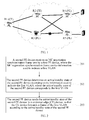
- FIG. 4 is a schematic structural diagram of a CE device, R1, dual-homed to two PE devices, R2 and R3.
- a servicel (service 1) encapsulates a VLAN4, and accesses to an R4 through an active/standby PW
- a service2 (service 2) encapsulates a VLAN5, and accesses to an R5 through an active/standby PW.
- an MC synchronization protocol is first run between the R2 and the R3, and an identification of a VLAN or a VLAN group, where the VLAN or the VLAN group is supported by the R2 and the R3 separately and priority information of the VLAN or the VLAN group are added to the MC synchronization protocol.
- the R2 and the R3 negotiate, by using the MC synchronization protocol, an active PE of the VLAN4, such as the R3, and an active PE of the VLAN5, such as the R2.
- a multi-chassis link aggregation group protocol is run between the R1 and the R2, and between the R1 and the R3 respectively.
- active/standby state information of the R2 and active/standby state information of the R3 is added, that is, in an LACP message sent by the R2 to the R1, information that the R2 is an active PE device of the VLAN5 and the R2 is a standby PE device of the VLAN4 is added, and in an LACP message sent by the R3 to the R1, information that the R3 is an active PE device of the VLAN4 and the R3 is a standby PE device of the VLAN5 is added.
- traffic of the servicel passes through a link from the R1 to the R3, and data traffic of the service2 passes through a link from the R1 to the R2, and the problem that a service is distinguished to perform load sharing is overcome.
- the R2 upgrades to be an active PE device of the service1, and in this case, service traffic of the servicel is switched to the R2 device, and service traffic of the original service 2 is not affected by the fault and does not need to be switched.
- the servicel related to this PW is switched to the R2 device, if there is a service 3 that uses the R3 as an active PE device, and uses a PW from the R3 to the R5 as an active PW, the service 3 is not affected.
- the R3 upgrades to be an active PE device of the service2, and in this case, service traffic of the service2 is switched to the R3 device, and service traffic of the original servicel is not affected by the fault and does not need to be switched.
- FIG. 5 is a block diagram of components of a load sharing PE device according to an embodiment of the present invention.
- the PE device includes:
- the first VLAN is a VLAN supported by the first PE device, and may include: at least one VLAN, or at least one VLAN group, or at least one VLAN and at least one VLAN group.
- the information used to indicate the first VLAN may include: an identification of the first VLAN and priority information of the first VLAN in the first PE device.
- the identification of the first VLAN may be a VLAN ID, or a VLAN group ID.
- the determining unit 52 may include:
- the sending unit 53 is specifically configured to send, through a LACP message, the active/standby state of the load sharing PE device to the customer edge CE device.
- a TLV Type Length Value, type length value
- the sending unit 53 may also carry its active/standby state information through other protocol messages or other manners (for example: manners such as reusing an original field).
- Respective components of the PE device in this embodiment are respectively configured to implement respective steps in the method of the embodiment shown in FIG. 2 . Because respective steps are illustrated in detail in the method of the embodiment shown in FIG. 2 , details are not repeatedly described here.
- FIG. 6 is a block diagram of components of a CE device according to an embodiment of the present invention.
- the CE device includes:
- the active/standby state of the at least one PE device may be carried through an expanded TLV in an LACP message.
- Respective components of the CE device in this embodiment are respectively configured to implement respective steps in the method of the embodiment shown in FIG. 3 . Because respective steps are illustrated in detail in the method of the embodiment shown in FIG. 3 , details are not repeatedly described here.
- FIG. 7 is a block diagram of components of a load sharing system according to an embodiment of the present invention.
- the load sharing system includes:
- the PE device 71 may send the active/standby state to the CE device 72 through a TLV added in an LACP message.
- the PE device 71 in this embodiment may be implemented through the PE device in the embodiment shown in FIG. 5
- the CE device 72 may be implemented through the CE device in the embodiment shown in FIG. 6 . Because the PE device and the CE device are illustrated in detail in the embodiments shown in FIG. 5 and FIG. 6 , details are not repeatedly described here.
- load sharing system provided in the embodiment of the present invention, load sharing based on a VLAN is implemented, and a massive waste of bandwidths and a service interruption caused by unnecessary service convergence may be avoided.
- the described steps of the method or an algorithm may be directly implemented by using hardware, a software module executed by a processor, or the combination of the two.
- the software module may be disposed in a random access memory (RAM), a memory, a read-only memory (ROM), an electrically programmable ROM, an electrically erasable programmable ROM, a register, a hard disk, a removable magnetic disk, a CD-ROM, or any storage medium of other forms well-known in the technical field.
Landscapes
- Engineering & Computer Science (AREA)
- Computer Networks & Wireless Communication (AREA)
- Signal Processing (AREA)
- Computer Security & Cryptography (AREA)
- Data Exchanges In Wide-Area Networks (AREA)
Applications Claiming Priority (1)
| Application Number | Priority Date | Filing Date | Title |
|---|---|---|---|
| PCT/CN2011/073399 WO2011113395A2 (zh) | 2011-04-27 | 2011-04-27 | 一种负载分担方法和装置 |
Publications (2)
| Publication Number | Publication Date |
|---|---|
| EP2677702A2 true EP2677702A2 (de) | 2013-12-25 |
| EP2677702A4 EP2677702A4 (de) | 2014-06-11 |
Family
ID=44649659
Family Applications (1)
| Application Number | Title | Priority Date | Filing Date |
|---|---|---|---|
| EP11755712.4A Withdrawn EP2677702A4 (de) | 2011-04-27 | 2011-04-27 | Verfahren und vorrichtung für lastausgleich |
Country Status (5)
| Country | Link |
|---|---|
| US (1) | US20140050092A1 (de) |
| EP (1) | EP2677702A4 (de) |
| CN (1) | CN102239670B (de) |
| AU (1) | AU2011229566B2 (de) |
| WO (1) | WO2011113395A2 (de) |
Families Citing this family (6)
| Publication number | Priority date | Publication date | Assignee | Title |
|---|---|---|---|---|
| CN102647355B (zh) * | 2012-04-12 | 2014-11-05 | 华为技术有限公司 | Lacp协商处理方法、中继节点及系统 |
| CN102811153B (zh) * | 2012-08-17 | 2015-05-27 | 杭州华三通信技术有限公司 | Vlan状态的协商方法及边缘设备 |
| GB201417149D0 (en) * | 2014-09-29 | 2014-11-12 | Metaswitch Networks Ltd | Method of operating a network node, network node, system and computer-readable medium |
| JPWO2018003106A1 (ja) * | 2016-06-30 | 2018-12-20 | 株式会社日立製作所 | スイッチ間通信管理装置、スイッチ間通信管理方法及びコンピュータ読取可能記録媒体 |
| CN111491334B (zh) * | 2019-01-29 | 2021-05-25 | 中兴通讯股份有限公司 | 负载分担方法、装置、系统、单板及存储介质 |
| CN113810260A (zh) * | 2020-06-17 | 2021-12-17 | 中国联合网络通信集团有限公司 | 网络组网方法和系统 |
Family Cites Families (19)
| Publication number | Priority date | Publication date | Assignee | Title |
|---|---|---|---|---|
| US7580417B2 (en) * | 2006-08-07 | 2009-08-25 | Cisco Technology, Inc. | Method and apparatus for load balancing over virtual network links |
| CN100450038C (zh) * | 2006-09-29 | 2009-01-07 | 杭州华三通信技术有限公司 | 一种链路负载分担的方法及转发设备 |
| CN100561970C (zh) * | 2007-05-28 | 2009-11-18 | 杭州华三通信技术有限公司 | 一种实现负载分担的方法和装置 |
| CN101179510B (zh) * | 2007-12-13 | 2011-11-23 | 中兴通讯股份有限公司 | 用于虚拟交换系统的主备链路负荷分担方法和装置 |
| CN101291276B (zh) * | 2008-06-18 | 2010-12-08 | 中国电信股份有限公司 | 一种基于业务的隧道保护方法和系统 |
| EP2304904B1 (de) * | 2008-06-27 | 2012-09-26 | Telefonaktiebolaget LM Ericsson (publ) | Verfahren und System zur Streckenaggregation |
| WO2010052028A1 (en) * | 2008-11-07 | 2010-05-14 | Nokia Siemens Networks Oy | Inter-network carrier ethernet service protection |
| US8503329B2 (en) * | 2009-08-05 | 2013-08-06 | Cisco Technology, Inc. | Signaling of attachment circuit status and automatic discovery of inter-chassis communication peers |
| JP5347836B2 (ja) * | 2009-08-25 | 2013-11-20 | 富士通株式会社 | 通信装置および通信方法 |
| CN101640644B (zh) * | 2009-09-01 | 2011-11-16 | 杭州华三通信技术有限公司 | 基于灵活链路组的流量均衡方法和设备 |
| CN101710877B (zh) * | 2009-12-04 | 2012-02-15 | 华为技术有限公司 | 基于伪线的业务流量处理方法、设备和系统 |
| EP2529512B1 (de) * | 2010-01-29 | 2016-05-04 | Hewlett Packard Development Company, L.P. | Konfiguration von netzwerkverknüpfungen in einer virtuellen verbindungsumgebung |
| US8724456B1 (en) * | 2010-05-19 | 2014-05-13 | Juniper Networks, Inc. | Network path selection for multi-homed edges to ensure end-to-end resiliency |
| US8488608B2 (en) * | 2010-08-04 | 2013-07-16 | Alcatel Lucent | System and method for traffic distribution in a multi-chassis link aggregation |
| US8472447B2 (en) * | 2010-08-04 | 2013-06-25 | Alcatel Lucent | IP multicast snooping and routing with multi-chassis link aggregation |
| US8582423B2 (en) * | 2010-08-04 | 2013-11-12 | Alcatel Lucent | Multi-chassis inter-process communication |
| JP5609995B2 (ja) * | 2011-02-04 | 2014-10-22 | 富士通株式会社 | 通信システム、通信方法及び通信装置 |
| US8650285B1 (en) * | 2011-03-22 | 2014-02-11 | Cisco Technology, Inc. | Prevention of looping and duplicate frame delivery in a network environment |
| US9225549B2 (en) * | 2012-08-06 | 2015-12-29 | Lenovo Enterprise Solutions (Singapore) Pte. Ltd. | Multi-chassis link aggregation in a distributed virtual bridge |
-
2011
- 2011-04-27 CN CN201180000516.0A patent/CN102239670B/zh not_active Expired - Fee Related
- 2011-04-27 WO PCT/CN2011/073399 patent/WO2011113395A2/zh not_active Ceased
- 2011-04-27 EP EP11755712.4A patent/EP2677702A4/de not_active Withdrawn
- 2011-04-27 AU AU2011229566A patent/AU2011229566B2/en not_active Ceased
-
2013
- 2013-10-24 US US14/061,972 patent/US20140050092A1/en not_active Abandoned
Also Published As
| Publication number | Publication date |
|---|---|
| AU2011229566A1 (en) | 2013-10-10 |
| AU2011229566B2 (en) | 2015-12-10 |
| US20140050092A1 (en) | 2014-02-20 |
| CN102239670A (zh) | 2011-11-09 |
| WO2011113395A3 (zh) | 2012-03-22 |
| WO2011113395A2 (zh) | 2011-09-22 |
| EP2677702A4 (de) | 2014-06-11 |
| CN102239670B (zh) | 2015-08-19 |
Similar Documents
| Publication | Publication Date | Title |
|---|---|---|
| US20220131740A1 (en) | Method and system of a dynamic high-availability mode based on current wide area network connectivity | |
| US11349687B2 (en) | Packet processing method, device, and system | |
| US8593945B2 (en) | Connectivity fault management traffic indication extension | |
| KR101652649B1 (ko) | 그레이스풀 리스타트 가능 이웃의 rsvp 헬로 억제를 이용한 시스템 및 방법 | |
| CN101309185B (zh) | 堆叠系统中多主用设备的处理方法和堆叠成员设备 | |
| US8908537B2 (en) | Redundant network connections | |
| US9385944B2 (en) | Communication system, path switching method and communication device | |
| AU2011229566B2 (en) | Load sharing method and apparatus | |
| CN105656645A (zh) | 堆叠系统的故障处理的决策方法和装置 | |
| EP3029883B1 (de) | Netzwerkschutzverfahren und vorrichtung, next-ring-knoten und system | |
| KR20150007623A (ko) | 패킷 전달 시스템에서의 보호 절체 방법 및 장치 | |
| US9647878B2 (en) | Announcement method, device and system | |
| CN103731303A (zh) | 一种纵向融合架构接口实现多活性实体检测的方法及设备 | |
| EP3001612B1 (de) | Schutzverfahren und -knoten für ein mehrdomänen-netzwerk | |
| CN101252525B (zh) | 一种pon网络中的链路备份方法和设备 | |
| CN102064998A (zh) | 一种以太网路径的保护切换方法及系统 |
Legal Events
| Date | Code | Title | Description |
|---|---|---|---|
| PUAI | Public reference made under article 153(3) epc to a published international application that has entered the european phase |
Free format text: ORIGINAL CODE: 0009012 |
|
| 17P | Request for examination filed |
Effective date: 20130917 |
|
| AK | Designated contracting states |
Kind code of ref document: A2 Designated state(s): AL AT BE BG CH CY CZ DE DK EE ES FI FR GB GR HR HU IE IS IT LI LT LU LV MC MK MT NL NO PL PT RO RS SE SI SK SM TR |
|
| A4 | Supplementary search report drawn up and despatched |
Effective date: 20140513 |
|
| RIC1 | Information provided on ipc code assigned before grant |
Ipc: H04L 12/70 20130101AFI20140509BHEP |
|
| DAX | Request for extension of the european patent (deleted) | ||
| 17Q | First examination report despatched |
Effective date: 20150416 |
|
| STAA | Information on the status of an ep patent application or granted ep patent |
Free format text: STATUS: THE APPLICATION IS DEEMED TO BE WITHDRAWN |
|
| 18D | Application deemed to be withdrawn |
Effective date: 20160405 |