EP2678193B1 - Ensemble comportant un capot de vehicule automobile equipe d'une gache reliee a ce capot par des pattes deformables en cas de choc pieton - Google Patents
Ensemble comportant un capot de vehicule automobile equipe d'une gache reliee a ce capot par des pattes deformables en cas de choc pieton Download PDFInfo
- Publication number
- EP2678193B1 EP2678193B1 EP12706646.2A EP12706646A EP2678193B1 EP 2678193 B1 EP2678193 B1 EP 2678193B1 EP 12706646 A EP12706646 A EP 12706646A EP 2678193 B1 EP2678193 B1 EP 2678193B1
- Authority
- EP
- European Patent Office
- Prior art keywords
- vehicle
- hood
- assembly
- lugs
- bonnet
- Prior art date
- Legal status (The legal status is an assumption and is not a legal conclusion. Google has not performed a legal analysis and makes no representation as to the accuracy of the status listed.)
- Active
Links
- 210000000689 upper leg Anatomy 0.000 claims description 11
- 239000002184 metal Substances 0.000 claims description 5
- 229910000831 Steel Inorganic materials 0.000 claims description 3
- 239000010959 steel Substances 0.000 claims description 3
- 230000035939 shock Effects 0.000 description 15
- 210000002414 leg Anatomy 0.000 description 8
- 230000015556 catabolic process Effects 0.000 description 3
- 208000027418 Wounds and injury Diseases 0.000 description 2
- 230000006378 damage Effects 0.000 description 2
- 208000014674 injury Diseases 0.000 description 2
- 210000001364 upper extremity Anatomy 0.000 description 2
- 230000000694 effects Effects 0.000 description 1
- 238000009863 impact test Methods 0.000 description 1
Images

Classifications
-
- B—PERFORMING OPERATIONS; TRANSPORTING
- B60—VEHICLES IN GENERAL
- B60R—VEHICLES, VEHICLE FITTINGS, OR VEHICLE PARTS, NOT OTHERWISE PROVIDED FOR
- B60R21/00—Arrangements or fittings on vehicles for protecting or preventing injuries to occupants or pedestrians in case of accidents or other traffic risks
- B60R21/34—Protecting non-occupants of a vehicle, e.g. pedestrians
-
- E—FIXED CONSTRUCTIONS
- E05—LOCKS; KEYS; WINDOW OR DOOR FITTINGS; SAFES
- E05B—LOCKS; ACCESSORIES THEREFOR; HANDCUFFS
- E05B77/00—Vehicle locks characterised by special functions or purposes
- E05B77/02—Vehicle locks characterised by special functions or purposes for accident situations
- E05B77/08—Arrangements for protection of pedestrians
-
- B—PERFORMING OPERATIONS; TRANSPORTING
- B60—VEHICLES IN GENERAL
- B60R—VEHICLES, VEHICLE FITTINGS, OR VEHICLE PARTS, NOT OTHERWISE PROVIDED FOR
- B60R21/00—Arrangements or fittings on vehicles for protecting or preventing injuries to occupants or pedestrians in case of accidents or other traffic risks
- B60R21/34—Protecting non-occupants of a vehicle, e.g. pedestrians
- B60R2021/343—Protecting non-occupants of a vehicle, e.g. pedestrians using deformable body panel, bodywork or components
Definitions
- the present invention relates to an assembly comprising a front hood of a motor vehicle equipped with a keeper which is connected to this hood by deformable metal tabs in the event of impact of a pedestrian on this hood.
- the invention also relates to a motor vehicle equipped with such an assembly.
- DE112004000307 T5 discloses a front cover according to the preamble of claim 1.
- the metal tabs that connect the striker to the hood allow deforming to absorb the energy of the pedestrian impact on the hood and thus protect the pedestrian against the risk of serious injury, when the vehicle is traveling at low speed.
- the two tabs are rectilinear, that is to say do not include a fold.
- the two deformable tabs comprise zones of lesser resistance which play, in the event of a pedestrian impact, the role of hinges allowing the rotation of the striker rearwardly.
- This rotation of the strike reduces the risk of injury in the event of a pedestrian impact on the hood.
- the weaker zones weaken the tabs and may cause an inadvertent breakage thereof for example in case of overcladding of the hood.
- connection between the cover and the striker does not deform during closing, that is to say the breakdown of the cover.
- the object of the present invention is to propose a solution that makes it possible to obtain the above compromise.
- an assembly comprising a front hood of a motor vehicle and a device for locking this hood comprising a striker adapted to be able to lock to a lock fixed to a rigid part of the vehicle body, this striker being connected to the inner face of the hood by two metal tabs spaced from each other in the longitudinal direction of the vehicle, these two tabs being deformable in the event of impact of a pedestrian on the hood, characterized in that the lug located at the front of the other lug is substantially straight and is, when the assembly is mounted on the vehicle, inclined rearwardly relative to the vertical direction of the vehicle, the lug at the rear being also inclined backwards with respect to the vertical direction and having a curvature.
- front leg is straight allows it to withstand the forces generated during the breakdown of the hood.
- this tab is tilted back allows it to pivot backwards during a shock of the femur of a pedestrian.
- the rear leg has a curvature allows it to deform in case of impact of the head of a child in a hood area slightly away from the lock area.
- the invention thus provides the solution to the problem mentioned above.
- the convexity of the curvature of the lug at the rear is directed towards the tab at the front.
- the ends of the two deformable tabs opposite the cover are each connected to a rigid striker wire.
- the ends of the two deformable tabs are attached to an area of the hood that is exposed to the impact of the head of a child pedestrian or the femur of an adult pedestrian.
- the angle of inclination of the tabs is between 10 and 30 °.
- This angle of inclination of the legs allows them to be almost perpendicular to the direction of impact in case of impact of the femur of a pedestrian or the head of a child.
- the length of the tabs is such that the distance between the striker and the hood skin is between 100 and 140 mm
- this distance is relatively small and is compatible with a low hood.
- said tabs each consist of a steel blade having a thickness of between 1 and 1.5 mm, the plane of the blade being, when the assembly is mounted on the motor vehicle , transverse to the longitudinal axis of the vehicle.
- the invention also relates to a motor vehicle equipped with an assembly according to the invention as defined above.
- the Figures 1 and 2 represent an assembly comprising a front cover 1 of a motor vehicle and a device for locking the cover 1 comprising a keeper 4 adapted to be locked to a lock 5 fixed to a rigid portion 3 of the vehicle body.
- the striker 4 is connected to the lining 2 of the cover 1 by two metal tabs 8, 9 spaced apart from each other in the longitudinal direction X of the vehicle.
- the lug 9 located at the front of the other leg 8 is substantially rectilinear and is, when the assembly is mounted on the vehicle, inclined rearwardly with respect to the vertical direction Z of the vehicle .
- the lug 8 located at the rear is also inclined rearwardly relative to the vertical direction Z and has a curvature.
- the Figures 1 and 2 also show that the convexity of the curvature of the leg 8 at the rear is directed towards the lug 9 located at the front.
- the ends 8a, 9a of the two deformable tabs 8, 9 opposite the cover 1 are each welded to a rigid striker wire 4.
- ends 8b, 9b of the two deformable tabs 8, 9 are attached to an area of the hood 1 which is exposed to the impact of the head of a child pedestrian or the femur of an adult pedestrian.
- the dotted rectangle 10 symbolizes the femur of a pedestrian and the dashed circle 11 symbolizes the head of a child who according to the standard pedestrian impact test impact the front of the vehicle respectively in directions D1 and D2.
- the direction D1 of the femoral shock is inclined by 30 ° relative to the horizontal, while the direction D2 of the head shock is inclined by 50 ° relative to the horizontal.
- the angle of inclination to the rear of the tabs 8, 9 with respect to the Z axis is between 10 and 30 °.
- the length of the tabs 8, 9 is such that the distance between the highest point of the striker 4 and the skin of the cover 1 is between 100 and 140 mm.
- the lugs 8, 9 are each constituted by a steel plate possibly perforated, with a thickness of between 1 and 1.5 mm.
- the plane of the blade is, when the assembly is mounted on the motor vehicle, transverse to the longitudinal axis X of the vehicle.
- the striker wire 4 has a front portion 4a S-shaped, an intermediate portion 4b of rectilinear shape and a rear portion 4c inclined upwardly.
- the shape of the striker wire 4 is adapted to avoid any interference with the rigid portion 3 of the vehicle body.
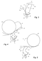
- the figure 3 illustrates the case of a femur shock.
- the dotted line L represents the initial position of the front lug 9.
- the femoral shock is applied in the direction D1 forming an angle of 30 ° with respect to the direction X.
- the direction of application D1 of the femoral shock is substantially perpendicular to the tabs 8 and 9.
- FIGS. 4 and 5 illustrate the case of the impact on the hood 1 of the head 11 of a child respectively in a zone close to the lock 5 (see figure 4 ) and in a zone slightly distant towards the rear of this zone.
- Another advantage of the invention lies in the fact that the distance d between the skin of the cover 1 and the striker thread 4 is less than 140 mm.
Landscapes
- Engineering & Computer Science (AREA)
- Mechanical Engineering (AREA)
- Superstructure Of Vehicle (AREA)
Description
- La présente invention concerne un ensemble comportant un capot avant de véhicule automobile équipé d'une gâche qui est reliée à ce capot par des pattes métalliques déformables en cas de choc d'un piéton sur ce capot.
- L'invention concerne également un véhicule automobile équipé d'un tel ensemble.
- Un ensemble de ce type a été décrit par exemple dans les brevets
FR 2 836 879 US 2007/7235237 . -
DE112004000307 T5 décrit un capot avant conformément au préambule de la revendication 1. - Les pattes métalliques qui relient la gâche au capot permettent en se déformant d'absorber l'énergie du choc du piéton sur le capot et de protéger ainsi le piéton contre les risques de blessures graves, lorsque le véhicule circule à faible vitesse.
- Dans les brevets ci-dessus, les deux pattes sont rectilignes, c'est-à-dire ne comportent pas de pli.
- Dans le cas de l'ensemble décrit dans le document
US 2007/7235237 , les deux pattes déformables comportent des zones de moindre résistance qui jouent, en cas de choc piéton, le rôle de charnières permettant la rotation de la gâche vers l'arrière. - Cette rotation de la gâche permet de réduire les risques de blessures en cas de choc du piéton sur le capot.
- Cependant, les zones de moindre résistance fragilisent les pattes et peuvent provoquer une rupture intempestive de celles-ci par exemple en cas de surclaquage du capot.
- Selon les nouvelles normes concernant les chocs piéton sur l'avant d'un véhicule automobile la zone avant du véhicule en particulier dans la zone située dans l'environnement de la serrure du capot doit être suffisamment souple pour ne pas être trop agressive lors de l'impact de :
- la hanche (ou du fémur) d'un piéton adulte,
- la tête d'un enfant.
- Il faut également que la liaison entre le capot et la gâche ne se déforme pas, lors de la fermeture, c'est-à-dire du claquage du capot.
- A cet effet, il faut trouver un bon compromis entre :
- la rigidité de la liaison ci-dessus lors du claquage du capot,
- la souplesse de cette liaison, lors d'un choc du fémur d'un piéton effectué sous un angle de 30°par rapport à l'horizontale,
- la souplesse de cette liaison, lors d'un choc de la tête d'un enfant effectué sous un angle de 50°par rapport à l'horizontale,
- un encombrement aussi réduit que possible de ladite liaison pour être compatible avec un capot bas.
- Le but de la présente invention est de proposer une solution permettant d'obtenir le compromis ci-dessus.
- Ce but est atteint, selon l'invention, grâce à un ensemble comportant un capot avant de véhicule automobile et un dispositif pour verrouiller ce capot comprenant une gâche adaptée pour pouvoir se verrouiller à une serrure fixée à une partie rigide de la caisse du véhicule, cette gâche étant reliée à la face intérieure du capot par deux pattes métalliques espacées l'une de l'autre suivant la direction longitudinale du véhicule, ces deux pattes étant déformables en cas de choc d'un piéton sur le capot, caractérisé en ce que la patte située à l'avant de l'autre patte est sensiblement rectiligne et est, lorsque l'ensemble est monté sur le véhicule, inclinée vers l'arrière par rapport à la direction verticale du véhicule, la patte située à l'arrière étant également inclinée vers l'arrière par rapport à la direction verticale et présentant une courbure.
- Le fait que la patte avant soit rectiligne lui permet de résister aux efforts engendrés lors du claquage du capot.
- Le fait que cette patte soit inclinée vers l'arrière lui permet de pivoter vers l'arrière lors d'un choc du fémur d'un piéton.
- Le fait que la patte arrière soit penchée vers l'arrière permet à celle-ci de se déformer en cas de choc de la tête d'un enfant dans une zone du capot proche de la serrure.
- Le fait que la patte arrière présente une courbure permet à celle-ci de se déformer en cas de choc de la tête d'un enfant dans une zone du capot légèrement éloignée de la zone de la serrure.
- L'invention apporte ainsi la solution au problème évoqué plus haut.
- De préférence, la convexité de la courbure de la patte située à l'arrière est dirigée vers la patte située à l'avant.
- Dans une version préférée de l'invention, les extrémités des deux pattes déformables opposées au capot sont chacunes reliées à un fil de gâche rigide.
- De préférence également, les extrémités des deux pattes déformables sont fixées à une zone du capot qui est exposée au choc de la tête d'un piéton enfant ou au fémur d'un piéton adulte.
- Dans un mode de réalisation particulièrement avantageux de l'invention, l'angle d'inclinaison des pattes est compris entre 10 et 30°.
- Cet angle d'inclinaison des pattes permet à celles-ci d'être presque perpendiculaires à la direction de l'impact en cas de choc du fémur d'un piéton ou de la tête d'un enfant.
- De préférence également, la longueur des pattes est telle que la distance comprise entre la gâche et la peau du capot est comprise entre 100 et 140 mm
- De ce fait, cette distance est relativement réduite et est compatible avec un capot bas.
- Dans un mode de réalisation préféré de l'invention, lesdites pattes sont constituées chacune par une lame en acier d'épaisseur comprise entre 1 et 1,5 mm, le plan de la lame étant, lorsque l'ensemble est monté sur le véhicule automobile, transversal à l'axe longitudinal du véhicule.
- Selon un autre aspect, l'invention concerne également un véhicule automobile équipé d'un ensemble selon l'invention tel que défini ci-dessus.
- D'autres particularités et avantages de l'invention apparaîtront encore tout au long de la description ci-après.
- Aux dessins annexés, donnés à titre d'exemples, non limitatifs :
- la
figure 1 est une vue en perspective d'un ensemble selon l'invention illustrant schématiquement l'impact sur cet ensemble d'un fémur d'un piéton et de la tête d'un enfant, - la
figure 2 est une vue en coupe longitudinale et verticale de l'ensemble selon l'invention, - la
figure 3 est une vue analogue à lafigure 2 montrant la déformation de l'ensemble lors d'un choc fémur, - la
figure 4 est une vue analogue à lafigure 2 montrant la déformation de l'ensemble, lors d'un choc de la tête d'un enfant dans une zone du capot proche de la serrure, - la
figure 5 est une vue analogue à lafigure 2 montrant la déformation de l'ensemble, lors d'un choc de la tête d'un enfant dans une zone du capot éloignée de la serrure. - Les
figures 1 et 2 représentent un ensemble comportant un capot avant 1 de véhicule automobile et un dispositif pour verrouiller ce capot 1 comprenant une gâche 4 adaptée pour pouvoir se verrouiller à une serrure 5 fixée à une partie rigide 3 de la caisse du véhicule. - La gâche 4 est reliée à la doublure 2 du capot 1 par deux pattes métalliques 8, 9 espacées l'une de l'autre suivant la direction longitudinale X du véhicule.
- Ces deux pattes 8, 9 sont déformables en cas de choc d'un piéton sur le capot 1.
- Conformément à l'invention, la patte 9 située à l'avant de l'autre patte 8 est sensiblement rectiligne et est, lorsque l'ensemble est monté sur le véhicule, inclinée vers l'arrière par rapport à la direction verticale Z du véhicule.
- La patte 8 située à l'arrière est également inclinée vers l'arrière par rapport à la direction verticale Z et présente une courbure.
- Les
figures 1 et 2 montrent également que la convexité de la courbure de la patte 8 située à l'arrière est dirigée vers la patte 9 située à l'avant. - Les extrémités 8a, 9a des deux pattes déformables 8, 9 opposées au capot 1 sont chacunes soudées à un fil de gâche rigide 4.
- Par ailleurs, les extrémités 8b, 9b des deux pattes déformables 8, 9 sont fixées à une zone du capot 1 qui est exposée au choc de la tête d'un piéton enfant ou au fémur d'un piéton adulte.
- Sur la
figure 1 , le rectangle 10 en pointillé symbolise le fémur d'un piéton et le cercle 11 en pointillé symbolise la tête d'un enfant qui selon le test de la norme choc piéton impactent l'avant du véhicule respectivement suivant des directions D1 et D2. - Selon cette norme, la direction D1 du choc fémur est inclinée de 30° par rapport à l'horizontale, tandis que la direction D2 du choc tête est inclinée de 50° par rapport à l'horizontale.
- De préférence, l'angle d'inclinaison vers l'arrière des pattes 8, 9 par rapport à l'axe Z est compris entre 10 et 30°.
- Par ailleurs, la longueur des pattes 8, 9 est telle que la distance comprise entre le point le plus haut de la gâche 4 et la peau du capot 1 est comprise entre 100 et 140 mm.
- En outre, les pattes 8, 9 sont constituées chacune par une lame en acier éventuellement ajourée, d'épaisseur comprise entre 1 et 1,5 mm.
- Le plan de la lame est, lorsque l'ensemble est monté sur le véhicule automobile, transversal à l'axe longitudinal X du véhicule.
- Dans l'exemple représenté, le fil de gâche 4 présente une partie avant 4a de forme en S, une partie intermédiaire 4b de forme rectiligne et une partie arrière 4c inclinée vers le haut.
- La forme du fil de gâche 4 est adaptée pour éviter toute interférence avec la partie rigide 3 de la caisse du véhicule.
- Lors de la fermeture, c'est-à-dire du claquage du capot 1, les efforts sont transmis vers le fil de gâche 4 dans le sens de la flèche F, représentée sur la
figure 2 . - Du fait qu'elle soit rectiligne, la patte avant 9 résiste sans se déformer aux efforts ci-dessus.
- La
figure 3 illustre le cas d'un choc fémur. - Sur cette figure, la ligne en pointillé L représente la position initiale de la patte avant 9.
- Le choc fémur est appliqué dans la direction D1 formant un angle de 30° par rapport à la direction X.
- Du fait de l'inclinaison vers l'arrière des pattes 8 et 9, la direction D1 d'application du choc fémur est sensiblement perpendiculaire aux pattes 8 et 9.
- Cette inclinaison des pattes 8 et 9 favorise ainsi leur pivotement vers l'arrière, comme montré par la
figure 3 , qui permet d'absorber l'énergie du choc fémur. - Les
figures 4 et 5 illustrent le cas de l'impact sur le capot 1 de la tête 11 d'un enfant respectivement dans une zone proche de la serrure 5 (voirfigure 4 ) et dans une zone légèrement éloignée vers l'arrière de cette zone. - Dans les deux cas, les pattes 8 et 9, sous l'effet de l'impact, se replient vers l'arrière pour amortir le choc.
- Dans les deux cas, l'inclinaison initiale vers l'arrière des deux pattes 8 et 9 et la courbure de la patte arrière 8 favorisent la déformation des deux pattes.
- Un autre avantage de l'invention réside dans le fait que la distance d comprise entre la peau du capot 1 et le fil de gâche 4 soit inférieure à 140 mm.
- En effet, cette distance réduite permet de maintenir le profil bas du capot 1, c'est-à-dire évite de rehausser celui-ci pour pouvoir installer les pattes 8, 9.
Claims (8)
- Ensemble comportant un capot avant (1) de véhicule automobile et un dispositif pour verrouiller ce capot (1) comprenant une gâche (4) adaptée pour pouvoir se verrouiller à une serrure (5) fixée à une partie rigide de la caisse du véhicule, cette gâche (4) étant reliée à la face intérieure du capot (1) par deux pattes métalliques (8, 9) espacées l'une de l'autre suivant la direction longitudinale (X) du véhicule, ces deux pattes (8, 9) étant déformables en cas de choc d'un piéton sur le capot (1), caractérisé en ce que la patte (9) située à l'avant de l'autre patte (8) est sensiblement rectiligne et est, lorsque l'ensemble est monté sur le véhicule, inclinée vers l'arrière par rapport à la direction verticale (Z) du véhicule, la patte (8) située à l'arrière étant également inclinée vers l'arrière par rapport à la direction verticale (Z) et présentant une courbure.
- Ensemble selon la revendication 1, caractérisé en ce que la convexité de la courbure de la patte (8) située à l'arrière est dirigée vers la patte (9) située à l'avant.
- Ensemble selon l'une des revendications 1 ou 2, caractérisé en ce que les extrémités (8a, 9a) des deux pattes déformables (8, 9) opposées au capot (1) sont chacunes reliées à un fil de gâche rigide (4).
- Ensemble selon l'une des revendications 1 à 3, caractérisé en ce que les extrémités (8b, 9b) des deux pattes déformables (8, 9) sont fixées à une zone du capot (1) qui est exposée au choc de la tête d'un piéton enfant ou au fémur d'un piéton adulte.
- Ensemble selon l'une des revendications 1 à 4, caractérisé en ce que l'angle d'inclinaison des pattes (8, 9) est compris entre 10 et 30°.
- Ensemble selon l'une des revendications 1 à 5, caractérisé en ce que la longueur des pattes (8, 9) est telle que la distance (d) comprise entre la gâche (4) et la peau du capot (1) est comprise entre 100 et 140 mm.
- Ensemble selon l'une des revendications 1 à 6, caractérisé en ce que lesdites pattes (8, 9) sont constituées chacune par une lame en acier d'épaisseur comprise entre 1 et 1,5 mm, le plan de la lame étant, lorsque l'ensemble est monté sur le véhicule automobile, transversal à l'axe longitudinal (X) du véhicule.
- Véhicule automobile équipé d'un ensemble selon l'une des revendications 1 à 7.
Applications Claiming Priority (2)
| Application Number | Priority Date | Filing Date | Title |
|---|---|---|---|
| FR1151376A FR2971755B1 (fr) | 2011-02-21 | 2011-02-21 | Ensemble comportant un capot de vehicule automobile equipe d'une gache reliee a ce capot par des pattes deformables en cas de choc pieton |
| PCT/FR2012/050188 WO2012114010A1 (fr) | 2011-02-21 | 2012-01-30 | Ensemble comportant un capot de vehicule automobile equipe d'une gache reliee a ce capot par des pattes deformables en cas de choc pieton |
Publications (2)
| Publication Number | Publication Date |
|---|---|
| EP2678193A1 EP2678193A1 (fr) | 2014-01-01 |
| EP2678193B1 true EP2678193B1 (fr) | 2014-12-10 |
Family
ID=45774265
Family Applications (1)
| Application Number | Title | Priority Date | Filing Date |
|---|---|---|---|
| EP12706646.2A Active EP2678193B1 (fr) | 2011-02-21 | 2012-01-30 | Ensemble comportant un capot de vehicule automobile equipe d'une gache reliee a ce capot par des pattes deformables en cas de choc pieton |
Country Status (4)
| Country | Link |
|---|---|
| EP (1) | EP2678193B1 (fr) |
| ES (1) | ES2527404T3 (fr) |
| FR (1) | FR2971755B1 (fr) |
| WO (1) | WO2012114010A1 (fr) |
Families Citing this family (1)
| Publication number | Priority date | Publication date | Assignee | Title |
|---|---|---|---|---|
| DE102024119139B3 (de) * | 2024-07-05 | 2025-12-24 | Dr. Ing. H.C. F. Porsche Aktiengesellschaft | Kraftfahrzeug |
Family Cites Families (6)
| Publication number | Priority date | Publication date | Assignee | Title |
|---|---|---|---|---|
| FR2836879B1 (fr) | 2002-03-07 | 2004-07-02 | Peugeot Citroen Automobiles Sa | Vehicule automobile a securite renforcee en cas de choc pieton avant |
| GB2398545A (en) * | 2003-02-20 | 2004-08-25 | Autoliv Dev | Hinge assembly for raising the rear of a vehicle bonnet |
| DE10308371B4 (de) * | 2003-02-27 | 2007-08-30 | Daimlerchrysler Ag | Sicherheitseinrichtung |
| EP1842746B1 (fr) | 2006-04-04 | 2011-10-26 | Volvo Car Corporation | Capot de véhicule |
| FR2916730A3 (fr) * | 2007-05-30 | 2008-12-05 | Renault Sas | Structure de capot d'un vehicule automobile |
| EP2163460B1 (fr) * | 2007-07-10 | 2012-06-13 | Toyota Shatai Kabushiki Kaisha | Structure frontale de capot automobile |
-
2011
- 2011-02-21 FR FR1151376A patent/FR2971755B1/fr not_active Expired - Fee Related
-
2012
- 2012-01-30 EP EP12706646.2A patent/EP2678193B1/fr active Active
- 2012-01-30 ES ES12706646.2T patent/ES2527404T3/es active Active
- 2012-01-30 WO PCT/FR2012/050188 patent/WO2012114010A1/fr not_active Ceased
Also Published As
| Publication number | Publication date |
|---|---|
| FR2971755B1 (fr) | 2013-03-08 |
| EP2678193A1 (fr) | 2014-01-01 |
| WO2012114010A1 (fr) | 2012-08-30 |
| FR2971755A1 (fr) | 2012-08-24 |
| ES2527404T3 (es) | 2015-01-23 |
Similar Documents
| Publication | Publication Date | Title |
|---|---|---|
| FR2898316A1 (fr) | Dispositif pare-chocs pour vehicules automobiles | |
| WO2018078226A1 (fr) | Renfort de la structure avant d'un vehicule automobile pour choc frontal a faible recouvrement | |
| FR2867731A1 (fr) | Systeme de pare-chocs compose d'une traverse ayant un profil en forme de chapeau et de deux absorbeurs de chocs | |
| EP2539209B1 (fr) | Structure d'un vehicule comprenant un passage de roue a rigidite amelioree. | |
| EP1561647B1 (fr) | Doublure de calandre de véhicule automobile | |
| EP3164317A1 (fr) | Traverse transversale de renfort améliorée a rupture programmée | |
| EP2322413B1 (fr) | Poutre transversale avant de véhicule automobile comprenant un élément de carénage arrière | |
| EP1651503B1 (fr) | Longeron deformable pour vehicule automobile | |
| WO2012114010A1 (fr) | Ensemble comportant un capot de vehicule automobile equipe d'une gache reliee a ce capot par des pattes deformables en cas de choc pieton | |
| EP2393693B1 (fr) | Structure de l'avant de la caisse d'un vehicule automobile et vehicule comportant une telle structure | |
| FR3017361A1 (fr) | Raidisseur de la doublure de custode d'un vehicule automobile equipe d'un support pour la goulotte de remplissage en carburant | |
| EP4483028B1 (fr) | Pièce de butée optimisée pour un panneau arrière d'un véhicule | |
| WO2013175086A1 (fr) | Structure de l'avant d'un véhicule automobile permettant d'amortir le choc de la tête d'un piéton contre le capot | |
| FR2975353A1 (fr) | Ensemble comprenant une tablette en tole et un enrouleur de ceinture de securite fixe a cette tablette et vehicule automobile equipe d'un tel ensemble | |
| EP2379374A1 (fr) | Support de charnon mobile amortisseur de choc pieton | |
| EP1849664B1 (fr) | Dispositif de sécurité passif en cas de choc piéton avant d'un véhicule automobile et véhicule comprenant un tel dispositif | |
| EP2872718B1 (fr) | Charnière d'articulation d'un ouvrant du type capot de fermeture du compartiment moteur sur une caisse de véhicule automobile | |
| EP2771230B1 (fr) | Bouclier de vehicule automobile integrand un reflecteur d'air et vehicule correspondant | |
| FR2926280A1 (fr) | Element de renfort lateral pour bloc avant de vehicule automobile et vehicule automobile equipe d'un tel element | |
| EP3078527B1 (fr) | Dispositif de detrompage pour le montage correct d'une biellette anti-couple non symetrique dans le berceau d'un vehicule | |
| EP3898387B1 (fr) | Doublure de montant de baie comportant une nervure | |
| FR2937288A1 (fr) | Porte laterale de vehicule automobile comportant un raidisseur de renforcement a l'egard des chocs lateraux. | |
| EP2861483B1 (fr) | Structure de caisse d'un véhicule automobile | |
| EP1637442B1 (fr) | Face avant pour véhicule automobile et procédé de montage correspondant | |
| FR3139524A1 (fr) | Dispositif pour l’assemblage d’un PARECHOC ARRIÈRE de VÉHICULE AUTOMOBILE |
Legal Events
| Date | Code | Title | Description |
|---|---|---|---|
| PUAI | Public reference made under article 153(3) epc to a published international application that has entered the european phase |
Free format text: ORIGINAL CODE: 0009012 |
|
| 17P | Request for examination filed |
Effective date: 20130710 |
|
| AK | Designated contracting states |
Kind code of ref document: A1 Designated state(s): AL AT BE BG CH CY CZ DE DK EE ES FI FR GB GR HR HU IE IS IT LI LT LU LV MC MK MT NL NO PL PT RO RS SE SI SK SM TR |
|
| DAX | Request for extension of the european patent (deleted) | ||
| GRAP | Despatch of communication of intention to grant a patent |
Free format text: ORIGINAL CODE: EPIDOSNIGR1 |
|
| RIC1 | Information provided on ipc code assigned before grant |
Ipc: B60R 21/34 20110101AFI20140610BHEP |
|
| INTG | Intention to grant announced |
Effective date: 20140701 |
|
| GRAS | Grant fee paid |
Free format text: ORIGINAL CODE: EPIDOSNIGR3 |
|
| GRAA | (expected) grant |
Free format text: ORIGINAL CODE: 0009210 |
|
| AK | Designated contracting states |
Kind code of ref document: B1 Designated state(s): AL AT BE BG CH CY CZ DE DK EE ES FI FR GB GR HR HU IE IS IT LI LT LU LV MC MK MT NL NO PL PT RO RS SE SI SK SM TR |
|
| REG | Reference to a national code |
Ref country code: GB Ref legal event code: FG4D Free format text: NOT ENGLISH |
|
| REG | Reference to a national code |
Ref country code: CH Ref legal event code: EP |
|
| REG | Reference to a national code |
Ref country code: IE Ref legal event code: FG4D Free format text: LANGUAGE OF EP DOCUMENT: FRENCH |
|
| REG | Reference to a national code |
Ref country code: AT Ref legal event code: REF Ref document number: 700487 Country of ref document: AT Kind code of ref document: T Effective date: 20150115 |
|
| REG | Reference to a national code |
Ref country code: DE Ref legal event code: R096 Ref document number: 602012004244 Country of ref document: DE Effective date: 20150122 |
|
| REG | Reference to a national code |
Ref country code: ES Ref legal event code: FG2A Ref document number: 2527404 Country of ref document: ES Kind code of ref document: T3 Effective date: 20150123 |
|
| REG | Reference to a national code |
Ref country code: AT Ref legal event code: MK05 Ref document number: 700487 Country of ref document: AT Kind code of ref document: T Effective date: 20141210 Ref country code: NL Ref legal event code: VDEP Effective date: 20141210 |
|
| REG | Reference to a national code |
Ref country code: NL Ref legal event code: VDEP Effective date: 20141210 |
|
| PG25 | Lapsed in a contracting state [announced via postgrant information from national office to epo] |
Ref country code: NO Free format text: LAPSE BECAUSE OF FAILURE TO SUBMIT A TRANSLATION OF THE DESCRIPTION OR TO PAY THE FEE WITHIN THE PRESCRIBED TIME-LIMIT Effective date: 20150310 Ref country code: FI Free format text: LAPSE BECAUSE OF FAILURE TO SUBMIT A TRANSLATION OF THE DESCRIPTION OR TO PAY THE FEE WITHIN THE PRESCRIBED TIME-LIMIT Effective date: 20141210 Ref country code: LT Free format text: LAPSE BECAUSE OF FAILURE TO SUBMIT A TRANSLATION OF THE DESCRIPTION OR TO PAY THE FEE WITHIN THE PRESCRIBED TIME-LIMIT Effective date: 20141210 |
|
| REG | Reference to a national code |
Ref country code: LT Ref legal event code: MG4D |
|
| PG25 | Lapsed in a contracting state [announced via postgrant information from national office to epo] |
Ref country code: GR Free format text: LAPSE BECAUSE OF FAILURE TO SUBMIT A TRANSLATION OF THE DESCRIPTION OR TO PAY THE FEE WITHIN THE PRESCRIBED TIME-LIMIT Effective date: 20150311 Ref country code: RS Free format text: LAPSE BECAUSE OF FAILURE TO SUBMIT A TRANSLATION OF THE DESCRIPTION OR TO PAY THE FEE WITHIN THE PRESCRIBED TIME-LIMIT Effective date: 20141210 Ref country code: AT Free format text: LAPSE BECAUSE OF FAILURE TO SUBMIT A TRANSLATION OF THE DESCRIPTION OR TO PAY THE FEE WITHIN THE PRESCRIBED TIME-LIMIT Effective date: 20141210 Ref country code: SE Free format text: LAPSE BECAUSE OF FAILURE TO SUBMIT A TRANSLATION OF THE DESCRIPTION OR TO PAY THE FEE WITHIN THE PRESCRIBED TIME-LIMIT Effective date: 20141210 Ref country code: HR Free format text: LAPSE BECAUSE OF FAILURE TO SUBMIT A TRANSLATION OF THE DESCRIPTION OR TO PAY THE FEE WITHIN THE PRESCRIBED TIME-LIMIT Effective date: 20141210 Ref country code: LV Free format text: LAPSE BECAUSE OF FAILURE TO SUBMIT A TRANSLATION OF THE DESCRIPTION OR TO PAY THE FEE WITHIN THE PRESCRIBED TIME-LIMIT Effective date: 20141210 |
|
| PG25 | Lapsed in a contracting state [announced via postgrant information from national office to epo] |
Ref country code: NL Free format text: LAPSE BECAUSE OF FAILURE TO SUBMIT A TRANSLATION OF THE DESCRIPTION OR TO PAY THE FEE WITHIN THE PRESCRIBED TIME-LIMIT Effective date: 20141210 |
|
| PG25 | Lapsed in a contracting state [announced via postgrant information from national office to epo] |
Ref country code: CZ Free format text: LAPSE BECAUSE OF FAILURE TO SUBMIT A TRANSLATION OF THE DESCRIPTION OR TO PAY THE FEE WITHIN THE PRESCRIBED TIME-LIMIT Effective date: 20141210 Ref country code: RO Free format text: LAPSE BECAUSE OF FAILURE TO SUBMIT A TRANSLATION OF THE DESCRIPTION OR TO PAY THE FEE WITHIN THE PRESCRIBED TIME-LIMIT Effective date: 20141210 Ref country code: SK Free format text: LAPSE BECAUSE OF FAILURE TO SUBMIT A TRANSLATION OF THE DESCRIPTION OR TO PAY THE FEE WITHIN THE PRESCRIBED TIME-LIMIT Effective date: 20141210 Ref country code: EE Free format text: LAPSE BECAUSE OF FAILURE TO SUBMIT A TRANSLATION OF THE DESCRIPTION OR TO PAY THE FEE WITHIN THE PRESCRIBED TIME-LIMIT Effective date: 20141210 Ref country code: PT Free format text: LAPSE BECAUSE OF FAILURE TO SUBMIT A TRANSLATION OF THE DESCRIPTION OR TO PAY THE FEE WITHIN THE PRESCRIBED TIME-LIMIT Effective date: 20150410 |
|
| REG | Reference to a national code |
Ref country code: CH Ref legal event code: PL |
|
| PG25 | Lapsed in a contracting state [announced via postgrant information from national office to epo] |
Ref country code: PL Free format text: LAPSE BECAUSE OF FAILURE TO SUBMIT A TRANSLATION OF THE DESCRIPTION OR TO PAY THE FEE WITHIN THE PRESCRIBED TIME-LIMIT Effective date: 20141210 Ref country code: IS Free format text: LAPSE BECAUSE OF FAILURE TO SUBMIT A TRANSLATION OF THE DESCRIPTION OR TO PAY THE FEE WITHIN THE PRESCRIBED TIME-LIMIT Effective date: 20150410 Ref country code: LU Free format text: LAPSE BECAUSE OF FAILURE TO SUBMIT A TRANSLATION OF THE DESCRIPTION OR TO PAY THE FEE WITHIN THE PRESCRIBED TIME-LIMIT Effective date: 20150130 |
|
| REG | Reference to a national code |
Ref country code: DE Ref legal event code: R097 Ref document number: 602012004244 Country of ref document: DE |
|
| PG25 | Lapsed in a contracting state [announced via postgrant information from national office to epo] |
Ref country code: MC Free format text: LAPSE BECAUSE OF FAILURE TO SUBMIT A TRANSLATION OF THE DESCRIPTION OR TO PAY THE FEE WITHIN THE PRESCRIBED TIME-LIMIT Effective date: 20141210 |
|
| PLBE | No opposition filed within time limit |
Free format text: ORIGINAL CODE: 0009261 |
|
| STAA | Information on the status of an ep patent application or granted ep patent |
Free format text: STATUS: NO OPPOSITION FILED WITHIN TIME LIMIT |
|
| PG25 | Lapsed in a contracting state [announced via postgrant information from national office to epo] |
Ref country code: LI Free format text: LAPSE BECAUSE OF NON-PAYMENT OF DUE FEES Effective date: 20150131 Ref country code: DK Free format text: LAPSE BECAUSE OF FAILURE TO SUBMIT A TRANSLATION OF THE DESCRIPTION OR TO PAY THE FEE WITHIN THE PRESCRIBED TIME-LIMIT Effective date: 20141210 Ref country code: CH Free format text: LAPSE BECAUSE OF NON-PAYMENT OF DUE FEES Effective date: 20150131 |
|
| REG | Reference to a national code |
Ref country code: IE Ref legal event code: MM4A |
|
| 26N | No opposition filed |
Effective date: 20150911 |
|
| REG | Reference to a national code |
Ref country code: FR Ref legal event code: PLFP Year of fee payment: 5 |
|
| PG25 | Lapsed in a contracting state [announced via postgrant information from national office to epo] |
Ref country code: IT Free format text: LAPSE BECAUSE OF FAILURE TO SUBMIT A TRANSLATION OF THE DESCRIPTION OR TO PAY THE FEE WITHIN THE PRESCRIBED TIME-LIMIT Effective date: 20141210 |
|
| REG | Reference to a national code |
Ref country code: DE Ref legal event code: R084 Ref document number: 602012004244 Country of ref document: DE |
|
| PG25 | Lapsed in a contracting state [announced via postgrant information from national office to epo] |
Ref country code: IE Free format text: LAPSE BECAUSE OF NON-PAYMENT OF DUE FEES Effective date: 20150130 |
|
| PG25 | Lapsed in a contracting state [announced via postgrant information from national office to epo] |
Ref country code: SI Free format text: LAPSE BECAUSE OF FAILURE TO SUBMIT A TRANSLATION OF THE DESCRIPTION OR TO PAY THE FEE WITHIN THE PRESCRIBED TIME-LIMIT Effective date: 20141210 |
|
| REG | Reference to a national code |
Ref country code: FR Ref legal event code: PLFP Year of fee payment: 6 |
|
| PG25 | Lapsed in a contracting state [announced via postgrant information from national office to epo] |
Ref country code: MT Free format text: LAPSE BECAUSE OF FAILURE TO SUBMIT A TRANSLATION OF THE DESCRIPTION OR TO PAY THE FEE WITHIN THE PRESCRIBED TIME-LIMIT Effective date: 20141210 |
|
| PG25 | Lapsed in a contracting state [announced via postgrant information from national office to epo] |
Ref country code: HU Free format text: LAPSE BECAUSE OF FAILURE TO SUBMIT A TRANSLATION OF THE DESCRIPTION OR TO PAY THE FEE WITHIN THE PRESCRIBED TIME-LIMIT; INVALID AB INITIO Effective date: 20120130 Ref country code: SM Free format text: LAPSE BECAUSE OF FAILURE TO SUBMIT A TRANSLATION OF THE DESCRIPTION OR TO PAY THE FEE WITHIN THE PRESCRIBED TIME-LIMIT Effective date: 20141210 Ref country code: BG Free format text: LAPSE BECAUSE OF FAILURE TO SUBMIT A TRANSLATION OF THE DESCRIPTION OR TO PAY THE FEE WITHIN THE PRESCRIBED TIME-LIMIT Effective date: 20141210 |
|
| PG25 | Lapsed in a contracting state [announced via postgrant information from national office to epo] |
Ref country code: CY Free format text: LAPSE BECAUSE OF FAILURE TO SUBMIT A TRANSLATION OF THE DESCRIPTION OR TO PAY THE FEE WITHIN THE PRESCRIBED TIME-LIMIT Effective date: 20141210 |
|
| PG25 | Lapsed in a contracting state [announced via postgrant information from national office to epo] |
Ref country code: BE Free format text: LAPSE BECAUSE OF NON-PAYMENT OF DUE FEES Effective date: 20150131 |
|
| PG25 | Lapsed in a contracting state [announced via postgrant information from national office to epo] |
Ref country code: TR Free format text: LAPSE BECAUSE OF FAILURE TO SUBMIT A TRANSLATION OF THE DESCRIPTION OR TO PAY THE FEE WITHIN THE PRESCRIBED TIME-LIMIT Effective date: 20141210 |
|
| REG | Reference to a national code |
Ref country code: FR Ref legal event code: PLFP Year of fee payment: 7 |
|
| PG25 | Lapsed in a contracting state [announced via postgrant information from national office to epo] |
Ref country code: MK Free format text: LAPSE BECAUSE OF FAILURE TO SUBMIT A TRANSLATION OF THE DESCRIPTION OR TO PAY THE FEE WITHIN THE PRESCRIBED TIME-LIMIT Effective date: 20141210 |
|
| REG | Reference to a national code |
Ref country code: FR Ref legal event code: CA Effective date: 20180312 Ref country code: FR Ref legal event code: CD Owner name: PEUGEOT CITROEN AUTOMOBILES SA, FR Effective date: 20180312 |
|
| PG25 | Lapsed in a contracting state [announced via postgrant information from national office to epo] |
Ref country code: AL Free format text: LAPSE BECAUSE OF FAILURE TO SUBMIT A TRANSLATION OF THE DESCRIPTION OR TO PAY THE FEE WITHIN THE PRESCRIBED TIME-LIMIT Effective date: 20141210 |
|
| PGFP | Annual fee paid to national office [announced via postgrant information from national office to epo] |
Ref country code: DE Payment date: 20211215 Year of fee payment: 11 |
|
| PGFP | Annual fee paid to national office [announced via postgrant information from national office to epo] |
Ref country code: ES Payment date: 20220201 Year of fee payment: 11 |
|
| PGFP | Annual fee paid to national office [announced via postgrant information from national office to epo] |
Ref country code: GB Payment date: 20221221 Year of fee payment: 12 |
|
| REG | Reference to a national code |
Ref country code: DE Ref legal event code: R119 Ref document number: 602012004244 Country of ref document: DE |
|
| PG25 | Lapsed in a contracting state [announced via postgrant information from national office to epo] |
Ref country code: DE Free format text: LAPSE BECAUSE OF NON-PAYMENT OF DUE FEES Effective date: 20230801 |
|
| REG | Reference to a national code |
Ref country code: ES Ref legal event code: FD2A Effective date: 20240403 |
|
| PG25 | Lapsed in a contracting state [announced via postgrant information from national office to epo] |
Ref country code: ES Free format text: LAPSE BECAUSE OF NON-PAYMENT OF DUE FEES Effective date: 20230131 |
|
| PG25 | Lapsed in a contracting state [announced via postgrant information from national office to epo] |
Ref country code: ES Free format text: LAPSE BECAUSE OF NON-PAYMENT OF DUE FEES Effective date: 20230131 |
|
| GBPC | Gb: european patent ceased through non-payment of renewal fee |
Effective date: 20240130 |
|
| PG25 | Lapsed in a contracting state [announced via postgrant information from national office to epo] |
Ref country code: GB Free format text: LAPSE BECAUSE OF NON-PAYMENT OF DUE FEES Effective date: 20240130 |
|
| PG25 | Lapsed in a contracting state [announced via postgrant information from national office to epo] |
Ref country code: GB Free format text: LAPSE BECAUSE OF NON-PAYMENT OF DUE FEES Effective date: 20240130 |
|
| PGFP | Annual fee paid to national office [announced via postgrant information from national office to epo] |
Ref country code: FR Payment date: 20241219 Year of fee payment: 14 |