EP2678986B1 - Betrieb von benutzergeräten bei kontroll- und dateninformationsversorgung von verschiedenen funkeinheiten - Google Patents
Betrieb von benutzergeräten bei kontroll- und dateninformationsversorgung von verschiedenen funkeinheiten Download PDFInfo
- Publication number
- EP2678986B1 EP2678986B1 EP12703773.7A EP12703773A EP2678986B1 EP 2678986 B1 EP2678986 B1 EP 2678986B1 EP 12703773 A EP12703773 A EP 12703773A EP 2678986 B1 EP2678986 B1 EP 2678986B1
- Authority
- EP
- European Patent Office
- Prior art keywords
- ich
- sub
- carriers
- pairs
- producing
- Prior art date
- Legal status (The legal status is an assumption and is not a legal conclusion. Google has not performed a legal analysis and makes no representation as to the accuracy of the status listed.)
- Not-in-force
Links
- 239000000969 carrier Substances 0.000 claims description 76
- 238000000034 method Methods 0.000 claims description 25
- 238000010295 mobile communication Methods 0.000 claims description 6
- 230000004044 response Effects 0.000 claims description 3
- 238000012937 correction Methods 0.000 description 11
- 230000010267 cellular communication Effects 0.000 description 6
- 230000009471 action Effects 0.000 description 5
- 230000008569 process Effects 0.000 description 5
- 230000005540 biological transmission Effects 0.000 description 4
- 238000012545 processing Methods 0.000 description 4
- 238000004891 communication Methods 0.000 description 3
- 230000006870 function Effects 0.000 description 3
- 238000012360 testing method Methods 0.000 description 3
- 241000760358 Enodes Species 0.000 description 2
- 230000006978 adaptation Effects 0.000 description 2
- 230000001413 cellular effect Effects 0.000 description 2
- 230000008859 change Effects 0.000 description 2
- 125000004122 cyclic group Chemical group 0.000 description 2
- 238000010586 diagram Methods 0.000 description 2
- 239000006185 dispersion Substances 0.000 description 2
- 238000005516 engineering process Methods 0.000 description 2
- 238000005259 measurement Methods 0.000 description 2
- 239000003795 chemical substances by application Substances 0.000 description 1
- 230000001427 coherent effect Effects 0.000 description 1
- 230000001143 conditioned effect Effects 0.000 description 1
- 230000001419 dependent effect Effects 0.000 description 1
- 238000001514 detection method Methods 0.000 description 1
- 230000000694 effects Effects 0.000 description 1
- 230000002045 lasting effect Effects 0.000 description 1
- 230000007774 longterm Effects 0.000 description 1
- 239000000203 mixture Substances 0.000 description 1
- 230000003287 optical effect Effects 0.000 description 1
- 230000003595 spectral effect Effects 0.000 description 1
Images



Classifications
-
- H—ELECTRICITY
- H04—ELECTRIC COMMUNICATION TECHNIQUE
- H04L—TRANSMISSION OF DIGITAL INFORMATION, e.g. TELEGRAPHIC COMMUNICATION
- H04L27/00—Modulated-carrier systems
- H04L27/26—Systems using multi-frequency codes
- H04L27/2601—Multicarrier modulation systems
- H04L27/2647—Arrangements specific to the receiver only
- H04L27/2655—Synchronisation arrangements
- H04L27/2657—Carrier synchronisation
-
- H—ELECTRICITY
- H04—ELECTRIC COMMUNICATION TECHNIQUE
- H04L—TRANSMISSION OF DIGITAL INFORMATION, e.g. TELEGRAPHIC COMMUNICATION
- H04L27/00—Modulated-carrier systems
- H04L27/26—Systems using multi-frequency codes
- H04L27/2601—Multicarrier modulation systems
- H04L27/2647—Arrangements specific to the receiver only
- H04L27/2655—Synchronisation arrangements
- H04L27/2662—Symbol synchronisation
-
- H—ELECTRICITY
- H04—ELECTRIC COMMUNICATION TECHNIQUE
- H04L—TRANSMISSION OF DIGITAL INFORMATION, e.g. TELEGRAPHIC COMMUNICATION
- H04L27/00—Modulated-carrier systems
- H04L27/26—Systems using multi-frequency codes
- H04L27/2601—Multicarrier modulation systems
- H04L27/2647—Arrangements specific to the receiver only
- H04L27/2655—Synchronisation arrangements
- H04L27/2668—Details of algorithms
- H04L27/2669—Details of algorithms characterised by the domain of operation
- H04L27/2672—Frequency domain
-
- H—ELECTRICITY
- H04—ELECTRIC COMMUNICATION TECHNIQUE
- H04L—TRANSMISSION OF DIGITAL INFORMATION, e.g. TELEGRAPHIC COMMUNICATION
- H04L27/00—Modulated-carrier systems
- H04L27/26—Systems using multi-frequency codes
- H04L27/2601—Multicarrier modulation systems
- H04L27/2647—Arrangements specific to the receiver only
- H04L27/2655—Synchronisation arrangements
- H04L27/2668—Details of algorithms
- H04L27/2673—Details of algorithms characterised by synchronisation parameters
- H04L27/2675—Pilot or known symbols
-
- H—ELECTRICITY
- H04—ELECTRIC COMMUNICATION TECHNIQUE
- H04L—TRANSMISSION OF DIGITAL INFORMATION, e.g. TELEGRAPHIC COMMUNICATION
- H04L27/00—Modulated-carrier systems
- H04L27/26—Systems using multi-frequency codes
- H04L27/2601—Multicarrier modulation systems
- H04L27/2647—Arrangements specific to the receiver only
- H04L27/2655—Synchronisation arrangements
- H04L27/2689—Link with other circuits, i.e. special connections between synchronisation arrangements and other circuits for achieving synchronisation
- H04L27/2695—Link with other circuits, i.e. special connections between synchronisation arrangements and other circuits for achieving synchronisation with channel estimation, e.g. determination of delay spread, derivative or peak tracking
-
- H—ELECTRICITY
- H04—ELECTRIC COMMUNICATION TECHNIQUE
- H04L—TRANSMISSION OF DIGITAL INFORMATION, e.g. TELEGRAPHIC COMMUNICATION
- H04L5/00—Arrangements affording multiple use of the transmission path
- H04L5/003—Arrangements for allocating sub-channels of the transmission path
- H04L5/0048—Allocation of pilot signals, i.e. of signals known to the receiver
- H04L5/005—Allocation of pilot signals, i.e. of signals known to the receiver of common pilots, i.e. pilots destined for multiple users or terminals
-
- H—ELECTRICITY
- H04—ELECTRIC COMMUNICATION TECHNIQUE
- H04L—TRANSMISSION OF DIGITAL INFORMATION, e.g. TELEGRAPHIC COMMUNICATION
- H04L5/00—Arrangements affording multiple use of the transmission path
- H04L5/003—Arrangements for allocating sub-channels of the transmission path
- H04L5/0048—Allocation of pilot signals, i.e. of signals known to the receiver
- H04L5/0051—Allocation of pilot signals, i.e. of signals known to the receiver of dedicated pilots, i.e. pilots destined for a single user or terminal
-
- H—ELECTRICITY
- H04—ELECTRIC COMMUNICATION TECHNIQUE
- H04W—WIRELESS COMMUNICATION NETWORKS
- H04W56/00—Synchronisation arrangements
- H04W56/001—Synchronization between nodes
-
- H—ELECTRICITY
- H04—ELECTRIC COMMUNICATION TECHNIQUE
- H04W—WIRELESS COMMUNICATION NETWORKS
- H04W56/00—Synchronisation arrangements
- H04W56/0035—Synchronisation arrangements detecting errors in frequency or phase
-
- H—ELECTRICITY
- H04—ELECTRIC COMMUNICATION TECHNIQUE
- H04L—TRANSMISSION OF DIGITAL INFORMATION, e.g. TELEGRAPHIC COMMUNICATION
- H04L25/00—Baseband systems
- H04L25/02—Details ; arrangements for supplying electrical power along data transmission lines
- H04L25/0202—Channel estimation
- H04L25/0204—Channel estimation of multiple channels
-
- H—ELECTRICITY
- H04—ELECTRIC COMMUNICATION TECHNIQUE
- H04L—TRANSMISSION OF DIGITAL INFORMATION, e.g. TELEGRAPHIC COMMUNICATION
- H04L25/00—Baseband systems
- H04L25/02—Details ; arrangements for supplying electrical power along data transmission lines
- H04L25/0202—Channel estimation
- H04L25/0224—Channel estimation using sounding signals
Definitions
- the present invention relates to cellular communication systems, and more particularly to the operation of user equipment when control and data information are supplied by different radio units in a cellular communication system.
- FIG. 1 illustrates a cellular communication system providing a system coverage area 101 by means of a plurality of cells 103.
- Present-day cellular communication systems are typically based on a homogenous network, mainly consisting of large macro cells, each cell having one transmitter/radio unit that serves the entire cell.
- heterogeneous network architectures can be expected comprising a mix of large macro and small pico/femto cells.
- a specific cell has several radio units.
- MIMO multiple-input-multiple-output
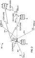
- FIG. 2 shows one such example involving a serving cell 200 with a main radio unit (MRU) 201, four remote radio units (RRU-1, RRU-2, RRU-3, and RRU-4), and three terminals denoted A, B, and C, respectively.
- Each of the remote radio units RRU-1...RRU-4 is connected to the MRU 201 by means of a respective link 203-1...203-4 (collectively referenced as "203").
- the main radio unit 201 is transmitting control channels (CCH) and common reference symbols (CRS) that are used by all terminals (A-C) connected to the cell 200.
- the CRS:s are used for demodulation of the CCH as well as for mobility measurements.
- the CRS:s are also used by each terminal for fine tuning in time and frequency synchronization operations.
- DRS dedicated reference symbols
- the DCH and DRS could furthermore be transmitted from different remote radio units (RRU-1...RRU-4) that might be closer to the terminal.
- terminal C gets both the DCH and the CCH from the main radio unit 201.
- terminals A and B each receive the CCH from the MRU 201 while data originates from one of the remote radio units (i.e., in this example RRU-3).
- the RRU:s could be distributed over the entire cell 200, thereby creating a network architecture that supports the use of advanced MIMO and beam forming schemes.
- LTE Long Term Evolution
- the inventors of the subject matter described herein have recognized one or more problems presented by arrangements such as that which is depicted in FIG. 2 .
- data and control signals originate from different radio units (e.g., CCH originating from the MRU 201 and DCH originating from one of the RRU:s)
- these signals can arrive with different timing at the terminal.
- the data from any given one of the RRU:s is time compensated by a network controlling node (in LTE, denoted the eNode B) in order to compensate for the delay in the cable/link 203 between the MRU 201 and the given RRU.
- LTE network controlling node
- the terminals are likely to move around, and depending on a given terminal's exact location (see, e.g., the different locations of terminals A and B), this strategy may not achieve exact time compensation; in fact, it is expected that a time difference of, approximately 0.5 - 1 microsecond between the CCH and DCH is likely.
- OFDM Orthogonal Frequency Division Multiplexing
- the CP itself can mitigate the effects of time dispersion.
- the classical time dispersion case is not presented because it does not involve different paths of the same signal, but rather different data (CCH+CRS vs. DCH+DRS) being transmitted from the two different radio units.
- each terminal relies on the CRS to synchronize its own timing and frequency, and there will be approximately up to 1 microsec difference between each terminal's expected timing (i.e., based on the CRS) and the actual DCH timing.
- a terminal performs a Fast Fourier Transform (FFT) on the received signal based on CRS information, a significant frequency rotation over the resource elements (i.e., a group of sub-carriers over a predefined period of time) in the frequency-domain is introduced in the data channel (relative to the control channel). The same holds for frequency error, but the rotation will be over a resource element in the time domain.
- FFT Fast Fourier Transform
- US 2010/323684 A1 discloses transmission of one of a plurality of reference signals, e.g. CRS or DRS, and that a User Agent (UA) is intermittently processing the transmission.
- the UA comprises a plurality of antenna ports and a processor configured to receive a first of the one reference signal and a second of the one reference signal on a respective antenna port set, wherein the first of the one reference signal and the second of the one reference signal are combined for the two antenna sets.
- 3GPP report R1-102287 discloses a pre-compensation method to reduce non-coherent carrier frequency error for cooperative transmissions from an eNB and a relay node.
- the accuracy in transmission frequency between the main and remote nodes should be within ⁇ 100-200 Hz, but assuming different sign on the frequency error between main node (MRU 201) and a remote node (RRU-x) there will be a significant frequency rotation in time between the CCH (which the terminal uses as frequency reference) and the DCH.
- the above-mentioned problem will introduce noise and modelling errors in the channel estimation process and thereby result in degraded receiver performance.
- the foregoing and other objects are achieved in, for example, methods and apparatuses for operating a mobile receiver in a mobile communication system, wherein the mobile communication system comprises first and second nodes, wherein the first node transmits common control signals and the second node transmits dedicated data signals.
- Such operation comprises determining a first timing of the common control signals and a second timing of the dedicated data signals, and/or a first frequency of the common control signals and a second frequency of the dedicated data signals.
- the receiver determines at least one of a first difference and a second difference, wherein the first difference is a difference between the first timing rotation of the common control signals and the second timing rotation of the dedicated data signals and the second difference is a difference between the first frequency rotation of the common control signals and the second frequency rotation of the dedicated data signals.
- An adapted timing of dedicated data signals is produced based on at least one of the first and second differences. The adapted timing is used to receive dedicated data signals.
- a first relationship result is determined by ascertaining whether the first difference, when the first difference is determined, satisfies a predetermined relationship with respect to a first threshold and determining a second relationship result by ascertaining whether the second difference, when the first difference is determined, satisfies a predetermined relationship with respect to a second threshold.
- producing the adapted timing of dedicated data signals is performed only in response to at least one of the first and second relationship results indicating satisfaction of a predetermined relationship.
- determining at least one of the second timing rotation of the dedicated data signals and the second frequency rotation of the dedicated data signals is based on dedicated reference signals received by the receiver.
- Determining the first frequency rotation of the common control signals can be achieved in any of a number of different ways.
- determining the first frequency rotation of the common control signals can, in some embodiments, comprise producing a plurality of Instant Channel Estimate (ICH) pairs by, for a plurality of pairs of first and second sub-carriers occurring at a first Orthogonal Frequency Division Multiplexing (OFDM) symbol time, wherein each of the first and second sub-carriers communicates a common reference symbol and for each pair of first and second sub-carriers, the first and second sub-carriers are adjacent pilot positions in the frequency domain:
- ICH Instant Channel Estimate
- OFDM Orthogonal Frequency Division Multiplexing
- determining the first frequency rotation of the common control signals comprises producing a plurality of Instant Channel Estimate (ICH) pairs by, for each of a plurality of Orthogonal Frequency Division Multiplexing (OFDM) symbols containing common reference symbols:
- ICH Instant Channel Estimate
- OFDM Orthogonal Frequency Division Multiplexing
- Determining the second frequency rotation of the dedicated data signals can be accomplished in any of a number of ways.
- determining the second frequency rotation of the dedicated data signals comprises producing a plurality of Instant Channel Estimate (ICH) pairs by, for a plurality of pairs of first and second sub-carriers located within a same contiguous block of sub-carriers allocated to the mobile receiver and occurring at a first Orthogonal Frequency Division Multiplexing (OFDM) symbol time, wherein each of the first and second sub-carriers communicates a dedicated reference symbol and for each pair of first and second sub-carriers, the first and second sub-carriers are adjacent pilot positions in the frequency domain:
- OFDM Orthogonal Frequency Division Multiplexing
- determining the second frequency rotation of the dedicated data signals comprises producing a plurality of Instant Channel Estimate (ICH) pairs by, for each of a plurality of Orthogonal Frequency Division Multiplexing (OFDM) symbols containing dedicated reference symbols:
- ICH Instant Channel Estimate
- OFDM Orthogonal Frequency Division Multiplexing
- determining the first timing rotation of the common control signals comprises producing a plurality of Instant Channel Estimate (ICH) pairs by, for a plurality of pairs of adjacent Orthogonal Frequency Division Multiplexing (OFDM) symbol times, performing, for each of one or more given sub-carriers that communicate a common reference symbol:
- ICH Instant Channel Estimate
- OFDM Orthogonal Frequency Division Multiplexing
- determining the second timing rotation of the dedicated data signals comprises producing a plurality of Instant Channel Estimate (ICH) pairs by, for a plurality of pairs of adjacent Orthogonal Frequency Division Multiplexing (OFDM) symbol times of time-wise adjacent dedicated reference symbols, performing, for each of one or more given sub-carriers that communicate a dedicated reference symbol:
- ICH Instant Channel Estimate
- OFDM Orthogonal Frequency Division Multiplexing
- scaling of the determined frequency is performed for sub-carriers located between the first and second sub-carriers, wherein the amount of scaling is based on the frequency distance between the first and second sub-carriers.
- scaling of the determined timing is performed for OFDM symbol times located between the first and second OFDM symbol times, wherein the amount of scaling is based on the timing distance between the first and second OFDM symbol times.
- circuitry configured to perform one or more described actions is used herein to refer to any such embodiment (i.e., one or more specialized circuits and/or one or more programmed processors).
- the invention can additionally be considered to be embodied entirely within any form of computer readable carrier, such as solid-state memory, magnetic disk, or optical disk containing an appropriate set of computer instructions that would cause a processor to carry out the techniques described herein.
- any such form of embodiments as described above may be referred to herein as "logic configured to” perform a described action, or alternatively as “logic that” performs a described action.
- a control unit of a terminal operating in a cell uses received common reference symbols to determine the timing and frequency error of the cell's control channel and uses received dedicated reference symbols to determine the timing and frequency error of its data channel. If the timing / frequency error for the data channel is different from that of the control channel, the terminal adapts its timing for the control channel and adapts its timing for the data channel, and these adaptations are made independent of one another. Such adaptation could be made by, for example, changing the timing of an FFT window used in reception, the particular change being dependent on whether it is a control channel or a data channel OFDM symbol being received.
- control channel timing is utilized to determine placement of the FFT window and thereby receive the control channel information
- post-FFT compensation is applied to the data channel resource elements by the amount of frequency shift introduced by the time/frequency difference between the control and data channels.
- each frame consists of ten sub-frames.
- each sub-frame has two slots, which can each have either six or seven consecutively occurring OFDM symbols. (The ability to configure the downlink to have only six OFDM symbols allows for each symbol to have a longer cyclic prefix, which can be useful for very large cells or when multicast communications are being performed.)
- FIG. 3 illustrates an LTE slot and sub-frame structure, including common reference symbols (CRS:s) and dedicated reference symbols (DRS:s) transmitted from one antenna port.
- Each sub-frame lasting 1 ms, consists of two slots and a variable number of resource blocks.
- a resource block is defined as 12 sub-carriers taking place during one slot time.
- Two resource blocks are depicted in each of the two slots depicted in FIG. 3 .
- the actual number of resource blocks allocated to a terminal will depend on the system bandwidth, which is configurable between 1.4-20 MHz.
- the CCH called the Physical Dedicated Control CHannel ("PDCCH”) in LTE systems, is transmitted in the first 1-3 (4 in 1.4 MHz -- not shown) OFDM symbols in a subframe.
- PDCH Physical Dedicated Control CHannel
- the PDCCH can occupy 1, 2, or 3 symbols, with the particular number being signalled in the first OFDM symbol in a sub-frame.
- the PDCCH conveys information informing about where different terminals can find their data (i.e., which resource blocks) as well as which modulation and coding schemes are being used.
- common reference symbols are transmitted in OFDM symbols 0, 4, 7 and 11 on every sixth sub-carrier in each sub-frame. It is noted that only the common reference symbols from one eNode B antenna port are shown. ("Antenna port" is the term used in 3rd Generation Partnership Project --"3GPP" -- systems.
- common reference antenna port is mapped to one physical antenna.
- the PDCCH and common reference symbols are always transmitted from the master radio unit 201.
- the PDSCH as well as the dedicated reference symbols could as mentioned above, be transmitted from master radio unit 203 or from a remote radio unit RRU-x.
- the dedicated reference symbols are transmitted on sub-carriers 1, 6, and 11 of each resource block during the last two OFDM symbols of each slot.
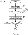
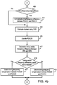
- FIGS. 4a and 4b are, in one respect, a flow chart of steps/processes performed by a UE in accordance with exemplary embodiments of the invention.
- FIGS. 4a and 4b can be considered to depict exemplary means 400 comprising various circuitry configured to perform the described functions.
- the terminal is connected to a serving cell. It is initially assumed that the timing and frequency are the same for both the control channel's reference symbols (PDCCH(CRS)) and the data channel's reference symbols (PDSCH(DRS)); accordingly, timing/frequency compensation of the data channel (PDSCH) is disabled (step 401).
- the terminal ascertains the timing/frequency-synchronization using the CRS:s (step 403). Techniques for doing this step are well known in the art and therefore need not be described here in further detail.
- the terminal receives the signal and uses the CRS:s to determine a channel estimate which is then used for demodulating the control channel (PDCCH) (step 405).
- PDCH control channel
- the terminal ascertains whether timing/frequency compensation of the data channel (PDSCH) is enabled (decision block 409). In case it is enabled ("Yes" path out of decision block 409), timing/frequency compensation of the data channel (PDSCH) is performed (step 411). If it is ascertained that timing/frequency compensation of the data channel is not enabled ("No" path out of decision block 409), then the compensation step is skipped.
- the channel is estimated using the (possibly compensated) dedicated reference symbols (DRS:s) (step 413), and the data is then decoded (step 415).
- DRS:s dedicated reference symbols
- the receiver updates the timing for the DRS:s and CRS:s and determines the timing and/or frequency difference(s) between them (step 417).
- the magnitude of this difference will determine whether timing/frequency compensation is needed in future receiving steps. Accordingly, it is ascertained whether the estimated timing and/or frequency difference(s) satisfy a predetermined relationship with respect to a threshold value (e.g., whether the difference is greater than a threshold value) (decision block 419). If yes ("Yes" path out of decision block 419) then timing/frequency compensation between the control and data channels is enabled (step 421). Otherwise (“No" path out of decision block 419), the timing/frequency compensation is disabled (step 423). Processing then reverts back to step 403 to process upcoming OFDM symbols.
- a threshold value e.g., whether the difference is greater than a threshold value
- an Instant Channel Estimate (ICH) for Resource Element (RE) position (t, f) (where "t” indicates time, and “f' indicates frequency) is defined as the received signal for the RE at (t, f) divided by the known pilot value for that position.
- a "resource element” is defined as one OFDM sub-carrier during one OFDM symbol interval.
- An ICH pair in the frequency direction is defined as the ICH at position (t, f1) multiplied by the complex conjugate ICH at position (t, f2), where f1 and f2 are two adjacent pilot positions in the frequency direction.
- ICH:s could be computed for each of the frequency-wise adjacent pilots 301 and 303 depicted in FIG. 3 , and these ICH:s could make up an ICH pair in the frequency direction.
- an ICH pair in the time direction is defined as the ICH at position (f, t1), where t1 and t2 are two adjacent pilot positions in the time direction.
- ICH:s could be computed for each of the time-wise adjacent pilots 301 and 305 depicted in FIG. 3 , and these ICH:s could make up an ICH pair in the time direction.
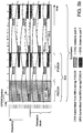
- FIG. 5a illustrates ICH pairs, including the ICH pairs 501-1, 501-2, 501-3, and 501-4, that can be summed to determine the rotation in the frequency direction. The sum may alternatively be over all OFDM symbols containing CRS:s to determine a rotation in time.
- FIG. 5b illustrates ICH pairs, including the ICH pairs 551-1 and 551-2, that can be summed to determine the rotation in the frequency direction. Then the rotation is defined as the arctangent of the imaginary part of the sum divided by the real part of the sum.
- the determination of the rotation in the frequency direction for the DRS is determined by summing over all ICH pairs containing DRS:s that are within the same resource block.
- the ICH pairs 503-1, 503-2, 503-3, and 503-4 illustrated in FIG. 5a could be summed to determine the frequency-wise rotation for the DRS:s.
- the sum may alternatively be over all OFDM symbols containing DRS:s within a sub-frame to produce a measure of time-wise rotation.
- the ICH pair 553-1 in FIG. 5b can be used as an indicator of the frequency-wise rotation for the DRS:s.
- the DRS pilots are Code Division Multiplexed with different orthogonal codes being assigned to ports 7 and 8, which means that the port 7 and port 8 pilots share two Resource Elements, such as the resource elements 307 and 309 depicted in FIG. 3 . Therefore, when finding an instant channel estimate, only one estimate for port 7 is obtained from two REs, for example on symbol 5 and 6.) Then the rotation is defined as the arctangent of the imaginary part of the sum divided by the real part of the sum.
- the rotation of the DRS:s in the time direction can be computed in a similar way as that which is described above with respect to rotation in the frequency direction.
- the difference in the computation is that the positions (f, t1) and (f, t2) should be used in an ICH pair and the positions should be adjacent in time direction.
- the ICH pair 553-1 can be used as an indicator of the time-wise rotation of the DRS:s.
- a hypothesis test is made to ascertain whether the CRS and DRS timing rotations are equal, and/or whether the CRS and DRS frequency rotations are equal.
- the test can be, for example, to ascertain whether the absolute value of the rotation difference is larger than a threshold value.
- the threshold could be different for the time and frequency errors. It is noted that the tests for time and frequency rotations should be made independent of one another because they have different sources.
- one compensation method comprises post-FFT compensation, in which a time / frequency de-rotation is made over the data (e.g., PDSCH (DRS)) resource elements.
- the de-rotation is herein defined as a multiplication between the REs and exp(-j*phi*k), where phi is the rotation difference in the time or frequency direction and k is the sub-carrier index or OFDM symbol number.
- An alternative way to compensate for frequency rotation is to change the placement of the FFT window that is used during OFDM reception.
- the FFT window placement could be changed between the control channel (e.g., PDCCH) OFDM symbols and the data channel (e.g., PDSCH) OFDM symbols. If the OFDM symbol contains both a CRS and a DRS, one could take two FFTs at different positions, one with timing relative the data channel and another relative to the control channel.
- the rotation obtained from any of the above-described techniques indicates how much the channel rotates between two adjacent common reference symbols.
- the reference symbols are generally not adjacent one another.
- the distance is 6 sub-carriers between two reference symbols (antenna port 0) in the frequency direction.
- the calculated rotation should be scaled by this distance; for example, in an LTE system, the equipment would divide by 6 to get the rotation between two sub-carriers.
- the rotation in time is similar, but in this case the distance is counted in symbols.
- For port 0 the distance is 7 symbols for normal CP (divide by 7).
- the distance in symbols is 7 symbols (divide by 7) and in frequency direction it is 5 subcarriers (divide by 5) within a Resource Block (RB) (the equipment should only sum within a RB for the DRS:s).
- RB Resource Block
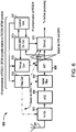
- FIG. 6 is a block diagram of an exemplary receiver 600 configured to carry out one or more of the aspects described above (e.g., as illustrated in FIG. 4 ).
- the receiver 600 is shown with one receiver antenna 601, but in alternative embodiments the number of antennas may be greater (e.g., for use with MIMO technology).
- the signal is received through the antenna 601 and down-converted in a front end receiver (FE RX) 603.
- the baseband signal supplied at the output of the front end receiver 603 is converted into digital form by an analog-to-digital converter 605.
- a digital filter 607 conditions the digital baseband signal by eliminating unwanted frequency components.
- the conditioned digital signal is supplied to FFT circuitry 609 that performs the FFT of the received baseband signals to obtain the signal representation in the frequency domain.
- the frequency domain signal is fed to a demodulator 611, in which the received data symbols are detected.
- the frequency domain signal is also fed to a channel estimation unit 613 that estimates channels based on the received CRS:s and DRS:s.
- the channel estimation unit 613 generates timing and/or frequency information about the control and data channels, and supplies this information to timing correction circuitry 615 as well as to the demodulator 611 and a control unit 617.
- the control unit 617 which may be embodied in any number of ways including but not limited to programmed processing circuitry and/or hardwired electronic circuitry, controls the operation of the channel estimation unit 613, the timing correction unit 615, and also a frequency correction unit 619.
- the control unit 617 is, in this exemplary embodiment, configured to generate control signals that cause the receiver circuitry to carry out functions such as those depicted in FIG. 4 .
- timing corrections and frequency corrections 619 generated by the respective timing correction circuitry 615 and frequency correction circuitry 619 may be based solely on the CRS:s, or they may include compensations to account for the control signals and data signals being transmitted from different nodes (e.g., control signals being transmitted from an eNodeB and data signals being transmitted from a remote node).
- Timing correction information generated by the timing correction circuitry 615 is supplied to the FFT circuitry 609 and to the demodulator 611 for use in known ways.
- Frequency correction information generated by the frequency correction circuitry 619 is supplied to the front end receiver 603, the digital filter 607, and to the demodulator 611, also for use in known ways.
Landscapes
- Engineering & Computer Science (AREA)
- Signal Processing (AREA)
- Computer Networks & Wireless Communication (AREA)
- Mobile Radio Communication Systems (AREA)
Claims (21)
- Verfahren zum Betreiben eines mobilen Empfängers in einem mobilen Kommunikationssystem, wobei das mobile Kommunikationssystem erste und zweite Knoten umfasst, wobei der erste Knoten gemeinsame Steuersignale überträgt und der zweite Knoten dedizierte Datensignale überträgt, das Verfahren gekennzeichnet durch
Bestimmen (403) eines ersten Timings der gemeinsamen Steuersignale und eines zweiten Timings der dedizierten Datensignale, und/oder einer ersten Frequenz der gemeinsamen Steuersignale und einer zweiten Frequenz der dedizierten Datensignale;
Bestimmen (417) mindestens einer von einer ersten Differenz und einer zweiten Differenz, wobei die erste Differenz eine Differenz zwischen dem ersten Timing der gemeinsamen Steuersignale und dem zweiten Timing der dedizierten Datensignale ist und die zweite Differenz eine Differenz zwischen der ersten Frequenz der gemeinsamen Steuersignale und der zweiten Frequenz der dedizierten Datensignale ist;
Erzeugen (411) eines angepassten Timings dedizierter Datensignale auf Grundlage mindestens einer der ersten und zweiten Differenzen; und
Verwenden (413, 415) des angepassten Timings zum Empfangen dedizierter Datensignale. - Verfahren nach Anspruch 1, umfassend mindestens eines von Folgendem:Bestimmen (419), nach dem Bestimmen der ersten Differenz, eines ersten Beziehungsergebnisses durch Ermitteln, ob die erste Differenz eine vorgegebene Beziehung hinsichtlich einer ersten Schwelle erfüllt; undBestimmen (419), nach dem Bestimmen der zweiten Differenz, eines zweiten Beziehungsergebnisses durch Ermitteln, ob die zweite Differenz eine vorgegebene Beziehung hinsichtlich einer zweiten Schwelle erfüllt,wobei das Erzeugen (411) des angepassten Timings dedizierter Datensignale nur als Reaktion auf mindestens eines der ersten und zweiten Beziehungsergebnisse erfolgt, das die Erfüllung einer vorgegebenen Beziehung angibt (419).
- Verfahren nach Anspruch 1, wobei das Bestimmen (403) der ersten Frequenz der gemeinsamen Steuersignale Folgendes umfasst:Erzeugen einer Vielzahl von ICH-(Instant Channel Estimate)-Paaren (501-1, 501-2, 501-3, 501-4) durch folgende Schritte für eine Vielzahl von Paaren erster und zweiter Subträger, die zu einer ersten OFDM-(Orthogonal Frequency Division Multiplexing)-Symbolzeit auftreten, wobei jeder der ersten und zweiten Subträger ein gemeinsames Referenzsymbol kommuniziert und für jedes Paar erster und zweiter Subträger die ersten und zweiten Subträger angrenzende Pilotpositionen in dem Frequenzbereich sind:Erzeugen einer ersten ICH für den ersten Subträger;Erzeugen einer zweiten ICH für den zweiten Subträger; undErzeugen eines ICH-Paars durch Multiplizieren der ersten ICH mit dem komplex Konjugierten der zweiten ICH; undBestimmen einer Frequenz durch Summieren der Vielzahl von ICH-Paaren.
- Verfahren nach Anspruch 1, wobei das Bestimmen (403) der zweiten Frequenz der dedizierten Datensignale Folgendes umfasst:Erzeugen einer Vielzahl von ICH-(Instant Channel Estimate)-Paaren (503-1, 503-2, 503-3, 503-4) durch folgende Schritte für eine Vielzahl von Paaren erster und zweiter Subträger, die sich innerhalb desselben, dem mobilen Empfänger zugeordneten zusammenhängenden Blocks befinden und zu einer ersten OFDM-(Orthogonal Frequency Division Multiplexing)-Symbolzeit auftreten, wobei jeder der ersten und zweiten Subträger ein dediziertes Referenzsymbol kommuniziert und für jedes Paar erster und zweiter Subträger die ersten und zweiten Subträger angrenzende Pilotpositionen in dem Frequenzbereich sind:Erzeugen einer ersten ICH für den ersten Subträger;Erzeugen einer zweiten ICH für den zweiten Subträger; undErzeugen eines ICH-Paars durch Multiplizieren der ersten ICH mit dem komplex Konjugierten der zweiten ICH; undBestimmen einer Frequenz durch Summieren der Vielzahl von ICH-Paaren.
- Verfahren nach Anspruch 1, wobei das Bestimmen (403) der ersten Frequenz der gemeinsamen Steuersignale Folgendes umfasst:
Erzeugen einer Vielzahl von ICH-(Instant Channel Estimate)-Paaren (501-1, 501-2, 501-3, 501-4) durch folgende Schritte für jede einer Vielzahl von OFDM-(Orthogonal Frequency Division Multiplexing)-Symbolen, die gemeinsame Referenzsymbole enthalten:Identifizieren von Paaren erster und zweiter Subträger, die Bestandteil des jeden OFDM-Symbols sind, wobei jeder der ersten und zweiten Subträger ein gemeinsames Referenzsymbol kommuniziert und für jedes Paar erster und zweiter Subträger die ersten und zweiten Subträger angrenzende Pilotpositionen in dem Frequenzbereich sind; undfür jedes der Paare erster und zweiter Subträger:Erzeugen einer ersten ICH für den ersten Subträger;Erzeugen einer zweiten ICH für den zweiten Subträger; undErzeugen eines ICH-Paars durch Multiplizieren der ersten ICH mit dem komplex Konjugierten der zweiten ICH; undBestimmen einer Frequenz als den Arcustangens des Imaginärteils der Summe der Vielzahl von ICH-Paaren geteilt durch den Realteil der Summe der Vielzahl von ICH-Paaren. - Verfahren nach Anspruch 1, wobei das Bestimmen (403) der zweiten Frequenz der dedizierten Datensignale Folgendes umfasst:Erzeugen einer Vielzahl von ICH-(Instant Channel Estimate)-Paaren (503-1, 503-2, 503-3, 503-4) durch folgende Schritte für jede einer Vielzahl von OFDM-(Orthogonal Frequency Division Multiplexing)-Symbolen, die dedizierte Referenzsymbole enthalten:Identifizieren von Paaren erster und zweiter Subträger, die sich innerhalb desselben, dem mobilen Empfänger zugeordneten zusammenhängenden Blocks befinden und die Bestandteil des jeden OFDM-Symbols sind, wobei jeder der ersten und zweiten Subträger ein dediziertes Referenzsymbol kommuniziert und für jedes Paar erster und zweiter Subträger die ersten und zweiten Subträger angrenzende Pilotpositionen in dem Frequenzbereich sind; undfür jedes der Paare erster und zweiter Subträger:Erzeugen einer ersten ICH für den ersten Subträger;Erzeugen einer zweiten ICH für den zweiten Subträger; undErzeugen eines ICH-Paars durch Multiplizieren der ersten ICH mit dem komplex Konjugierten der zweiten ICH; undBestimmen einer Frequenz als den Arcustangens des Imaginärteils der Summe der Vielzahl von ICH-Paaren geteilt durch den Realteil der Summe der Vielzahl von ICH-Paaren.
- Verfahren nach Anspruch 6, umfassend:
Skalieren der bestimmten Frequenz für Subträger, die sich zwischen dem ersten Subträger und dem zweiten Subträger befinden, wobei ein Betrag der Skalierung auf einem Frequenzabstand zwischen dem ersten Subträger und dem zweiten Subträger basiert. - Verfahren nach Anspruch 1, wobei das Bestimmen (403) des ersten Timings der gemeinsamen Steuersignale Folgendes umfasst:Erzeugen einer Vielzahl von ICH-(Instant Channel Estimate)-Paaren (551-1, 551-2) für eine Vielzahl von Paaren angrenzender OFDM-(Orthogonal Frequency Division Multiplexing)-Symbolzeiten zeitlich angrenzender gemeinsamer Referenzsymbole durch das Durchführen folgender Schritte für jeden eines oder mehrerer gegebener Subträger, die ein gemeinsames Referenzsymbol kommunizieren:Erzeugen einer ersten ICH für eine erste der OFDM-Symbolzeiten;Erzeugen einer zweiten ICH für eine zweite der OFDM-Symbolzeiten; undErzeugen eines ICH-Paars durch Multiplizieren der ersten ICH mit dem komplex Konjugierten der zweiten ICH; undBestimmen eines Timings durch Summieren der Vielzahl von ICH-Paaren.
- Verfahren nach Anspruch 1, wobei das Bestimmen (403) des zweiten Timings der dedizierten Datensignale Folgendes umfasst:Erzeugen einer Vielzahl von ICH-(Instant Channel Estimate)-Paaren (553-1) für eine Vielzahl von Paaren angrenzender OFDM-(Orthogonal Frequency Division Multiplexing)-Symbolzeiten zeitlich angrenzender dedizierter Referenzsymbole durch das Durchführen folgender Schritte für jeden eines oder mehrerer gegebener Subträger, die ein dediziertes Referenzsymbol kommunizieren:Erzeugen einer ersten ICH für eine erste der OFDM-Symbolzeiten;Erzeugen einer zweiten ICH für eine zweite der OFDM-Symbolzeiten; undErzeugen eines ICH-Paars durch Multiplizieren der ersten ICH mit dem komplex Konjugierten der zweiten ICH; undBestimmen eines Timings durch Summieren der Vielzahl von ICH-Paaren.
- Verfahren nach Anspruch 9, umfassend:
Skalieren des bestimmten Timings für Symbole, die sich zwischen der ersten der OFDM-Symbolzeiten und der zweiten der OFDM-Symbolzeiten befinden, wobei ein Betrag der Skalierung auf einem Symbolzeitabstand zwischen der ersten der OFDM-Symbolzeiten und der zweiten der OFDM-Symbolzeiten basiert. - Einrichtung (600) zum Betreiben eines mobilen Empfängers eines mobilen Kommunikationssystems, wobei das mobile Kommunikationssystem erste und zweite Knoten umfasst, wobei der erste Knoten gemeinsame Steuersignale überträgt und der zweite Knoten dedizierte Datensignale überträgt, die Einrichtung gekennzeichnet durch
Schaltung, konfiguriert zum Bestimmen eines ersten Timings der gemeinsamen Steuersignale und eines zweiten Timings der dedizierten Datensignale, und/oder einer ersten Frequenz der gemeinsamen Steuersignale und einer zweiten Frequenz der dedizierten Datensignale;
Schaltung, konfiguriert zum Bestimmen mindestens einer von einer ersten Differenz und einer zweiten Differenz, wobei die erste Differenz eine Differenz zwischen dem ersten Timing der gemeinsamen Steuersignale und dem zweiten Timing der dedizierten Datensignale ist und die zweite Differenz eine Differenz zwischen der ersten Frequenz der gemeinsamen Steuersignale und der zweiten Frequenz der dedizierten Datensignale ist;
Schaltung, konfiguriert zum Erzeugen eines angepassten Timings dedizierter Datensignale auf Grundlage mindestens einer der ersten und zweiten Differenzen; und
Schaltung, konfiguriert zum Verwenden des angepassten Timings zum Empfangen dedizierter Datensignale. - Einrichtung nach Anspruch 11, umfassend mindestens eines von Folgendem:Schaltung, konfiguriert zum Bestimmen, nach dem Bestimmen der ersten Differenz, eines ersten Beziehungsergebnisses durch Ermitteln, ob die erste Differenz eine vorgegebene Beziehung hinsichtlich einer ersten Schwelle erfüllt und Schaltung, konfiguriert zum Bestimmen, nach dem Bestimmen der zweiten Differenz, eines zweiten Beziehungsergebnisses durch Ermitteln, ob die zweite Differenz eine vorgegebene Beziehung hinsichtlich einer zweiten Schwelle erfüllt,wobei die Schaltung, die zum Erzeugen des angepassten Timings dedizierter Datensignale konfiguriert ist nur als Reaktion auf mindestens eines der ersten und zweiten Beziehungsergebnisse aktiviert wird, das die Erfüllung einer vorgegebenen Beziehung angibt.
- Einrichtung nach Anspruch 11, wobei die Schaltung, die zum Bestimmen mindestens eines des zweiten Timings der dedizierten Datensignale und der zweiten Frequenz der dedizierten Datensignale konfiguriert ist, die Bestimmung auf Grundlage dedizierter Referenzsignale vornimmt, die vom Empfänger empfangen werden.
- Einrichtung nach Anspruch 11, wobei die Schaltung, die zum Bestimmen der ersten Frequenz der gemeinsamen Steuersignale konfiguriert ist, Folgendes umfasst:Schaltung, konfiguriert zum Erzeugen einer Vielzahl von ICH-(Instant Channel Estimate)-Paaren durch folgende Schritte für eine Vielzahl von Paaren erster und zweiter Subträger, die zu einer ersten OFDM-(Orthogonal Frequency Division Multiplexing)-Symbolzeit auftreten, wobei jeder der ersten und zweiten Subträger ein gemeinsames Referenzsymbol kommuniziert und für jedes Paar erster und zweiter Subträger die ersten und zweiten Subträger angrenzende Pilotpositionen in dem Frequenzbereich sind:Erzeugen einer ersten ICH für den ersten Subträger;Erzeugen einer zweiten ICH für den zweiten Subträger; undErzeugen eines ICH-Paars durch Multiplizieren der ersten ICH mit dem komplex Konjugierten der zweiten ICH; undSchaltung, konfiguriert zum Bestimmen einer Frequenz durch Summieren der Vielzahl von ICH-Paaren.
- Einrichtung nach Anspruch 11, wobei die Schaltung, die zum Bestimmen der zweiten Frequenz der dedizierten Datensignale konfiguriert ist, Folgendes umfasst:Schaltung, konfiguriert zum Erzeugen einer Vielzahl von ICH-(Instant Channel Estimate)-Paaren durch folgende Schritte für eine Vielzahl von Paaren erster und zweiter Subträger, die sich innerhalb desselben, dem mobilen Empfänger zugeordneten zusammenhängenden Blocks befinden und zu einer ersten OFDM-(Orthogonal Frequency Division Multiplexing)-Symbolzeit auftreten, wobei jeder der ersten und zweiten Subträger ein dediziertes Referenzsymbol kommuniziert und für jedes Paar erster und zweiter Subträger die ersten und zweiten Subträger angrenzende Pilotpositionen in dem Frequenzbereich sind:Erzeugen einer ersten ICH für den ersten Subträger;Erzeugen einer zweiten ICH für den zweiten Subträger; undErzeugen eines ICH-Paars durch Multiplizieren der ersten ICH mit dem komplex Konjugierten der zweiten ICH; undSchaltung, konfiguriert zum Bestimmen einer Frequenz durch Summieren der Vielzahl von ICH-Paaren.
- Einrichtung nach Anspruch 11, wobei die Schaltung, die zum Bestimmen der ersten Frequenz der gemeinsamen Steuersignale konfiguriert ist, Folgendes umfasst:
Schaltung, konfiguriert zum Erzeugen einer Vielzahl von ICH-(Instant Channel Estimate)-Paaren durch folgende Schritte für jede einer Vielzahl von OFDM-(Orthogonal Frequency Division Multiplexing)-Symbolen, die gemeinsame Referenzsymbole enthalten:Identifizieren von Paaren erster und zweiter Subträger, die Bestandteil des jeden OFDM-Symbols sind, wobei jeder der ersten und zweiten Subträger ein gemeinsames Referenzsymbol kommuniziert und für jedes Paar erster und zweiter Subträger die ersten und zweiten Subträger angrenzende Pilotpositionen in dem Frequenzbereich sind; undfür jedes der Paare erster und zweiter Subträger:Erzeugen einer ersten ICH für den ersten Subträger;Erzeugen einer zweiten ICH für den zweiten Subträger; undErzeugen eines ICH-Paars durch Multiplizieren der ersten ICH mit dem komplex Konjugierten der zweiten ICH; undSchaltung, konfiguriert zum Bestimmen einer Frequenz als den Arcustangens des Imaginärteils der Summe der Vielzahl von ICH-Paaren geteilt durch den Realteil der Summe der Vielzahl von ICH-Paaren. - Einrichtung nach Anspruch 11, wobei die Schaltung, die zum Bestimmen der zweiten Frequenz der dedizierten Datensignale konfiguriert ist, Folgendes umfasst:Schaltung, konfiguriert zum Erzeugen einer Vielzahl von ICH-(Instant Channel Estimate)-Paaren durch folgende Schritte für jede einer Vielzahl von OFDM-(Orthogonal Frequency Division Multiplexing)-Symbolen, die dedizierte Referenzsymbole enthalten:Identifizieren von Paaren erster und zweiter Subträger, die sich innerhalb desselben, dem mobilen Empfänger zugeordneten zusammenhängenden Blocks befinden und die Bestandteil des jeden OFDM-Symbols sind, wobei jeder der ersten und zweiten Subträger ein dediziertes Referenzsymbol kommuniziert und für jedes Paar erster und zweiter Subträger die ersten und zweiten Subträger angrenzende Pilotpositionen in dem Frequenzbereich sind; undfür jedes der Paare erster und zweiter Subträger:Erzeugen einer ersten ICH für den ersten Subträger;Erzeugen einer zweiten ICH für den zweiten Subträger; undErzeugen eines ICH-Paars durch Multiplizieren der ersten ICH mit dem komplex Konjugierten der zweiten ICH; undSchaltung, konfiguriert zum Bestimmen einer Frequenz als den Arcustangens des Imaginärteils der Summe der Vielzahl von ICH-Paaren geteilt durch den Realteil der Summe der Vielzahl von ICH-Paaren.
- Verfahren nach Anspruch 17, umfassend:
Schaltung, konfiguriert zum Skalieren der bestimmten Frequenz für Subträger, die sich zwischen dem ersten Subträger und dem zweiten Subträger befinden, wobei ein Betrag der Skalierung auf einem Frequenzabstand zwischen dem ersten Subträger und dem zweiten Subträger basiert. - Einrichtung nach Anspruch 11, wobei die Schaltung, die zum Bestimmen des ersten Timings der gemeinsamen Steuersignale konfiguriert ist, Folgendes umfasst:Schaltung, konfiguriert zum Erzeugen einer Vielzahl von ICH-(Instant Channel Estimate)-Paaren für eine Vielzahl von Paaren angrenzender OFDM-(Orthogonal Frequency Division Multiplexing)-Symbolzeiten zeitlich angrenzender gemeinsamer Referenzsymbole durch das Durchführen folgender Schritte für jeden eines oder mehrerer gegebener Subträger, die ein gemeinsames Referenzsymbol kommunizieren:Erzeugen einer ersten ICH für eine erste der OFDM-Symbolzeiten;Erzeugen einer zweiten ICH für eine zweite der OFDM-Symbolzeiten; undErzeugen eines ICH-Paars durch Multiplizieren der ersten ICH mit dem komplex Konjugierten der zweiten ICH; undSchaltung, konfiguriert zum Bestimmen eines Timings durch Summieren der Vielzahl von ICH-Paaren.
- Einrichtung nach Anspruch 11, wobei die Schaltung, die zum Bestimmen des zweiten Timings der dedizierten Datensignale konfiguriert ist, Folgendes umfasst:Schaltung, konfiguriert zum Erzeugen einer Vielzahl von ICH-(Instant Channel Estimate)-Paaren für eine Vielzahl von Paaren angrenzender OFDM-(Orthogonal Frequency Division Multiplexing)-Symbolzeiten zeitlich angrenzender dedizierter Referenzsymbole durch das Durchführen folgender Schritte für jeden eines oder mehrerer gegebener Subträger, die ein dediziertes Referenzsymbol kommunizieren:Erzeugen einer ersten ICH für eine erste der OFDM-Symbolzeiten;Erzeugen einer zweiten ICH für eine zweite der OFDM-Symbolzeiten; undErzeugen eines ICH-Paars durch Multiplizieren der ersten ICH mit dem komplex Konjugierten der zweiten ICH; undSchaltung, konfiguriert zum Bestimmen eines Timings durch Summieren der Vielzahl von ICH-Paaren.
- Verfahren nach Anspruch 20, umfassend:
Schaltung, konfiguriert zum Skalieren des bestimmten Timings für Symbole, die sich zwischen der ersten der OFDM-Symbolzeiten und der zweiten der OFDM-Symbolzeiten befinden, wobei ein Betrag der Skalierung auf einem Symbolzeitabstand zwischen der ersten der OFDM-Symbolzeiten und der zweiten der OFDM-Symbolzeiten basiert.
Applications Claiming Priority (2)
| Application Number | Priority Date | Filing Date | Title |
|---|---|---|---|
| US13/033,722 US8520777B2 (en) | 2011-02-24 | 2011-02-24 | Operation of user equipment when control and data information are supplied by different radio units |
| PCT/EP2012/052006 WO2012113642A1 (en) | 2011-02-24 | 2012-02-07 | Operation of user equipment when control and data information are supplied by different radio units |
Publications (2)
| Publication Number | Publication Date |
|---|---|
| EP2678986A1 EP2678986A1 (de) | 2014-01-01 |
| EP2678986B1 true EP2678986B1 (de) | 2018-07-25 |
Family
ID=45592372
Family Applications (1)
| Application Number | Title | Priority Date | Filing Date |
|---|---|---|---|
| EP12703773.7A Not-in-force EP2678986B1 (de) | 2011-02-24 | 2012-02-07 | Betrieb von benutzergeräten bei kontroll- und dateninformationsversorgung von verschiedenen funkeinheiten |
Country Status (4)
| Country | Link |
|---|---|
| US (1) | US8520777B2 (de) |
| EP (1) | EP2678986B1 (de) |
| CN (1) | CN103370913B (de) |
| WO (1) | WO2012113642A1 (de) |
Families Citing this family (5)
| Publication number | Priority date | Publication date | Assignee | Title |
|---|---|---|---|---|
| US9307422B2 (en) * | 2011-07-07 | 2016-04-05 | Lg Electronics Inc. | Method and apparatus for performing a channel measurement through a receiving end in a wireless communication system |
| EP2826164B1 (de) * | 2012-03-16 | 2018-10-24 | Intel Corporation | Downsampling zellspezifischer referenzsignale (crs) für einen neuen trägertyp |
| TWI577159B (zh) * | 2015-08-13 | 2017-04-01 | 宏碁股份有限公司 | 資料分配方法、訊號接收方法、無線傳送及接收裝置 |
| CN107370588B (zh) * | 2016-05-13 | 2021-04-20 | 华为技术有限公司 | 参考信号的发送方法及设备 |
| CN110460378B (zh) * | 2018-05-08 | 2021-07-30 | 大唐移动通信设备有限公司 | 一种数据传输方法、基带单元及基站 |
Family Cites Families (7)
| Publication number | Priority date | Publication date | Assignee | Title |
|---|---|---|---|---|
| US8134994B2 (en) * | 2003-02-14 | 2012-03-13 | Alcatel Lucent | Method of scheduling on downlink and transmitting on uplink dedicated channels |
| WO2005088853A1 (en) * | 2004-03-09 | 2005-09-22 | Neocific Inc. | Methods and apparatus for random access in multi-carrier communication systems |
| KR20070027999A (ko) * | 2005-08-30 | 2007-03-12 | 삼성전자주식회사 | 광대역 다중 접속 통신 시스템에서 자원 할당 방법 및할당된 자원 수신 방법 |
| KR100802844B1 (ko) * | 2006-06-27 | 2008-02-12 | 최승원 | 직교주파수분할다중접속 시스템의 레인징 채널 처리 장치및 방법 |
| US8306012B2 (en) * | 2007-11-07 | 2012-11-06 | Telefonaktiebolaget L M Ericsson (Publ) | Channel estimation for synchronized cells in a cellular communication system |
| EP2454827B1 (de) | 2009-06-19 | 2019-03-27 | BlackBerry Limited | Downlink-referenzsignal für typ-ii-relais |
| WO2012061224A1 (en) * | 2010-11-05 | 2012-05-10 | Interdigital Patent Holdings, Inc. | Methods, apparatus and systems for applying almost blank subframe (abs) patterns |
-
2011
- 2011-02-24 US US13/033,722 patent/US8520777B2/en active Active
-
2012
- 2012-02-07 WO PCT/EP2012/052006 patent/WO2012113642A1/en not_active Ceased
- 2012-02-07 EP EP12703773.7A patent/EP2678986B1/de not_active Not-in-force
- 2012-02-07 CN CN201280010007.0A patent/CN103370913B/zh not_active Expired - Fee Related
Also Published As
| Publication number | Publication date |
|---|---|
| WO2012113642A1 (en) | 2012-08-30 |
| CN103370913B (zh) | 2017-02-15 |
| EP2678986A1 (de) | 2014-01-01 |
| US8520777B2 (en) | 2013-08-27 |
| CN103370913A (zh) | 2013-10-23 |
| US20120219094A1 (en) | 2012-08-30 |
Similar Documents
| Publication | Publication Date | Title |
|---|---|---|
| US8306012B2 (en) | Channel estimation for synchronized cells in a cellular communication system | |
| EP2777337B1 (de) | Mehrstufige zeit und frequenzsynchronization. | |
| US9106276B2 (en) | Method and apparatus for reference signal transmission and reception | |
| US9509461B2 (en) | Method and apparatus for transmitting and receiving signals in wireless communication system | |
| US10075858B2 (en) | Weighted RSRP measurement | |
| WO2016169492A1 (en) | Channel impulse response estimation for full-duplex communication networks | |
| US9185571B2 (en) | Employing reference signals in communications | |
| US20130281038A1 (en) | Receiving apparatus, frequency deviation calculating method, and medium storing computer program therein | |
| KR101505091B1 (ko) | 직교주파수분할 방식 기반의 무선통신 시스템에서 초기 동기화를 위한 장치 및 방법 | |
| US11985612B2 (en) | Method and apparatus for transmitting and receiving signal including cell information in communication system | |
| WO2008150226A2 (en) | Interference suppression in a multicarrier receiver | |
| CN105122752B (zh) | 估计频率偏移的设备及其方法 | |
| GB2509088A (en) | A reference sequence for synchronisation and channel estimation in local area communication scenarios | |
| US20150189608A1 (en) | LTE-Advanced Sample Clock Timing Acquisition | |
| EP3229523A1 (de) | Verfahren zur verringerung von uplink-interferenzen und basisstation | |
| EP2678986B1 (de) | Betrieb von benutzergeräten bei kontroll- und dateninformationsversorgung von verschiedenen funkeinheiten | |
| AU2017219686B2 (en) | NB-loT receiver operating at minimum sampling rate | |
| US20180183628A1 (en) | Wireless communication devices and channel estimation methods thereof | |
| WO2013001474A1 (en) | Estimation of frequency offset between a base station and mobile terminal | |
| US20100046360A1 (en) | Wireless communication method, receiving method, and wireless communication device | |
| EP2665207B1 (de) | Benutzergerät und Verfahren zur Funkverbindungsüberwachung | |
| US8644403B2 (en) | Operation of user equipment when control and data information are supplied by different radio units | |
| US10212679B1 (en) | Method and apparatus for delay spread estimation | |
| JP6824153B2 (ja) | Lteレシーバのための干渉推定 |
Legal Events
| Date | Code | Title | Description |
|---|---|---|---|
| PUAI | Public reference made under article 153(3) epc to a published international application that has entered the european phase |
Free format text: ORIGINAL CODE: 0009012 |
|
| 17P | Request for examination filed |
Effective date: 20130830 |
|
| AK | Designated contracting states |
Kind code of ref document: A1 Designated state(s): AL AT BE BG CH CY CZ DE DK EE ES FI FR GB GR HR HU IE IS IT LI LT LU LV MC MK MT NL NO PL PT RO RS SE SI SK SM TR |
|
| DAX | Request for extension of the european patent (deleted) | ||
| STAA | Information on the status of an ep patent application or granted ep patent |
Free format text: STATUS: EXAMINATION IS IN PROGRESS |
|
| 17Q | First examination report despatched |
Effective date: 20171114 |
|
| REG | Reference to a national code |
Ref country code: DE Ref legal event code: R079 Ref document number: 602012048824 Country of ref document: DE Free format text: PREVIOUS MAIN CLASS: H04L0027260000 Ipc: H04L0005000000 |
|
| GRAP | Despatch of communication of intention to grant a patent |
Free format text: ORIGINAL CODE: EPIDOSNIGR1 |
|
| STAA | Information on the status of an ep patent application or granted ep patent |
Free format text: STATUS: GRANT OF PATENT IS INTENDED |
|
| RIC1 | Information provided on ipc code assigned before grant |
Ipc: H04L 25/02 20060101ALI20180319BHEP Ipc: H04L 5/00 20060101AFI20180319BHEP |
|
| INTG | Intention to grant announced |
Effective date: 20180410 |
|
| GRAS | Grant fee paid |
Free format text: ORIGINAL CODE: EPIDOSNIGR3 |
|
| GRAA | (expected) grant |
Free format text: ORIGINAL CODE: 0009210 |
|
| STAA | Information on the status of an ep patent application or granted ep patent |
Free format text: STATUS: THE PATENT HAS BEEN GRANTED |
|
| AK | Designated contracting states |
Kind code of ref document: B1 Designated state(s): AL AT BE BG CH CY CZ DE DK EE ES FI FR GB GR HR HU IE IS IT LI LT LU LV MC MK MT NL NO PL PT RO RS SE SI SK SM TR |
|
| REG | Reference to a national code |
Ref country code: GB Ref legal event code: FG4D |
|
| REG | Reference to a national code |
Ref country code: CH Ref legal event code: EP |
|
| REG | Reference to a national code |
Ref country code: AT Ref legal event code: REF Ref document number: 1022914 Country of ref document: AT Kind code of ref document: T Effective date: 20180815 |
|
| REG | Reference to a national code |
Ref country code: IE Ref legal event code: FG4D |
|
| REG | Reference to a national code |
Ref country code: DE Ref legal event code: R096 Ref document number: 602012048824 Country of ref document: DE |
|
| REG | Reference to a national code |
Ref country code: NL Ref legal event code: MP Effective date: 20180725 |
|
| REG | Reference to a national code |
Ref country code: LT Ref legal event code: MG4D |
|
| PG25 | Lapsed in a contracting state [announced via postgrant information from national office to epo] |
Ref country code: NL Free format text: LAPSE BECAUSE OF FAILURE TO SUBMIT A TRANSLATION OF THE DESCRIPTION OR TO PAY THE FEE WITHIN THE PRESCRIBED TIME-LIMIT Effective date: 20180725 |
|
| REG | Reference to a national code |
Ref country code: AT Ref legal event code: MK05 Ref document number: 1022914 Country of ref document: AT Kind code of ref document: T Effective date: 20180725 |
|
| PG25 | Lapsed in a contracting state [announced via postgrant information from national office to epo] |
Ref country code: SE Free format text: LAPSE BECAUSE OF FAILURE TO SUBMIT A TRANSLATION OF THE DESCRIPTION OR TO PAY THE FEE WITHIN THE PRESCRIBED TIME-LIMIT Effective date: 20180725 Ref country code: BG Free format text: LAPSE BECAUSE OF FAILURE TO SUBMIT A TRANSLATION OF THE DESCRIPTION OR TO PAY THE FEE WITHIN THE PRESCRIBED TIME-LIMIT Effective date: 20181025 Ref country code: AT Free format text: LAPSE BECAUSE OF FAILURE TO SUBMIT A TRANSLATION OF THE DESCRIPTION OR TO PAY THE FEE WITHIN THE PRESCRIBED TIME-LIMIT Effective date: 20180725 Ref country code: PL Free format text: LAPSE BECAUSE OF FAILURE TO SUBMIT A TRANSLATION OF THE DESCRIPTION OR TO PAY THE FEE WITHIN THE PRESCRIBED TIME-LIMIT Effective date: 20180725 Ref country code: LT Free format text: LAPSE BECAUSE OF FAILURE TO SUBMIT A TRANSLATION OF THE DESCRIPTION OR TO PAY THE FEE WITHIN THE PRESCRIBED TIME-LIMIT Effective date: 20180725 Ref country code: RS Free format text: LAPSE BECAUSE OF FAILURE TO SUBMIT A TRANSLATION OF THE DESCRIPTION OR TO PAY THE FEE WITHIN THE PRESCRIBED TIME-LIMIT Effective date: 20180725 Ref country code: IS Free format text: LAPSE BECAUSE OF FAILURE TO SUBMIT A TRANSLATION OF THE DESCRIPTION OR TO PAY THE FEE WITHIN THE PRESCRIBED TIME-LIMIT Effective date: 20181125 Ref country code: FI Free format text: LAPSE BECAUSE OF FAILURE TO SUBMIT A TRANSLATION OF THE DESCRIPTION OR TO PAY THE FEE WITHIN THE PRESCRIBED TIME-LIMIT Effective date: 20180725 Ref country code: NO Free format text: LAPSE BECAUSE OF FAILURE TO SUBMIT A TRANSLATION OF THE DESCRIPTION OR TO PAY THE FEE WITHIN THE PRESCRIBED TIME-LIMIT Effective date: 20181025 Ref country code: GR Free format text: LAPSE BECAUSE OF FAILURE TO SUBMIT A TRANSLATION OF THE DESCRIPTION OR TO PAY THE FEE WITHIN THE PRESCRIBED TIME-LIMIT Effective date: 20181026 |
|
| PG25 | Lapsed in a contracting state [announced via postgrant information from national office to epo] |
Ref country code: LV Free format text: LAPSE BECAUSE OF FAILURE TO SUBMIT A TRANSLATION OF THE DESCRIPTION OR TO PAY THE FEE WITHIN THE PRESCRIBED TIME-LIMIT Effective date: 20180725 Ref country code: HR Free format text: LAPSE BECAUSE OF FAILURE TO SUBMIT A TRANSLATION OF THE DESCRIPTION OR TO PAY THE FEE WITHIN THE PRESCRIBED TIME-LIMIT Effective date: 20180725 Ref country code: AL Free format text: LAPSE BECAUSE OF FAILURE TO SUBMIT A TRANSLATION OF THE DESCRIPTION OR TO PAY THE FEE WITHIN THE PRESCRIBED TIME-LIMIT Effective date: 20180725 |
|
| REG | Reference to a national code |
Ref country code: DE Ref legal event code: R097 Ref document number: 602012048824 Country of ref document: DE |
|
| PG25 | Lapsed in a contracting state [announced via postgrant information from national office to epo] |
Ref country code: CZ Free format text: LAPSE BECAUSE OF FAILURE TO SUBMIT A TRANSLATION OF THE DESCRIPTION OR TO PAY THE FEE WITHIN THE PRESCRIBED TIME-LIMIT Effective date: 20180725 Ref country code: RO Free format text: LAPSE BECAUSE OF FAILURE TO SUBMIT A TRANSLATION OF THE DESCRIPTION OR TO PAY THE FEE WITHIN THE PRESCRIBED TIME-LIMIT Effective date: 20180725 Ref country code: EE Free format text: LAPSE BECAUSE OF FAILURE TO SUBMIT A TRANSLATION OF THE DESCRIPTION OR TO PAY THE FEE WITHIN THE PRESCRIBED TIME-LIMIT Effective date: 20180725 Ref country code: IT Free format text: LAPSE BECAUSE OF FAILURE TO SUBMIT A TRANSLATION OF THE DESCRIPTION OR TO PAY THE FEE WITHIN THE PRESCRIBED TIME-LIMIT Effective date: 20180725 Ref country code: ES Free format text: LAPSE BECAUSE OF FAILURE TO SUBMIT A TRANSLATION OF THE DESCRIPTION OR TO PAY THE FEE WITHIN THE PRESCRIBED TIME-LIMIT Effective date: 20180725 |
|
| PG25 | Lapsed in a contracting state [announced via postgrant information from national office to epo] |
Ref country code: SK Free format text: LAPSE BECAUSE OF FAILURE TO SUBMIT A TRANSLATION OF THE DESCRIPTION OR TO PAY THE FEE WITHIN THE PRESCRIBED TIME-LIMIT Effective date: 20180725 Ref country code: SM Free format text: LAPSE BECAUSE OF FAILURE TO SUBMIT A TRANSLATION OF THE DESCRIPTION OR TO PAY THE FEE WITHIN THE PRESCRIBED TIME-LIMIT Effective date: 20180725 Ref country code: DK Free format text: LAPSE BECAUSE OF FAILURE TO SUBMIT A TRANSLATION OF THE DESCRIPTION OR TO PAY THE FEE WITHIN THE PRESCRIBED TIME-LIMIT Effective date: 20180725 |
|
| PLBE | No opposition filed within time limit |
Free format text: ORIGINAL CODE: 0009261 |
|
| STAA | Information on the status of an ep patent application or granted ep patent |
Free format text: STATUS: NO OPPOSITION FILED WITHIN TIME LIMIT |
|
| 26N | No opposition filed |
Effective date: 20190426 |
|
| PG25 | Lapsed in a contracting state [announced via postgrant information from national office to epo] |
Ref country code: SI Free format text: LAPSE BECAUSE OF FAILURE TO SUBMIT A TRANSLATION OF THE DESCRIPTION OR TO PAY THE FEE WITHIN THE PRESCRIBED TIME-LIMIT Effective date: 20180725 |
|
| REG | Reference to a national code |
Ref country code: CH Ref legal event code: PL |
|
| PG25 | Lapsed in a contracting state [announced via postgrant information from national office to epo] |
Ref country code: MC Free format text: LAPSE BECAUSE OF FAILURE TO SUBMIT A TRANSLATION OF THE DESCRIPTION OR TO PAY THE FEE WITHIN THE PRESCRIBED TIME-LIMIT Effective date: 20180725 Ref country code: LU Free format text: LAPSE BECAUSE OF NON-PAYMENT OF DUE FEES Effective date: 20190207 |
|
| REG | Reference to a national code |
Ref country code: BE Ref legal event code: MM Effective date: 20190228 |
|
| REG | Reference to a national code |
Ref country code: IE Ref legal event code: MM4A |
|
| PG25 | Lapsed in a contracting state [announced via postgrant information from national office to epo] |
Ref country code: LI Free format text: LAPSE BECAUSE OF NON-PAYMENT OF DUE FEES Effective date: 20190228 Ref country code: CH Free format text: LAPSE BECAUSE OF NON-PAYMENT OF DUE FEES Effective date: 20190228 |
|
| PG25 | Lapsed in a contracting state [announced via postgrant information from national office to epo] |
Ref country code: IE Free format text: LAPSE BECAUSE OF NON-PAYMENT OF DUE FEES Effective date: 20190207 |
|
| PG25 | Lapsed in a contracting state [announced via postgrant information from national office to epo] |
Ref country code: BE Free format text: LAPSE BECAUSE OF NON-PAYMENT OF DUE FEES Effective date: 20190228 |
|
| PG25 | Lapsed in a contracting state [announced via postgrant information from national office to epo] |
Ref country code: TR Free format text: LAPSE BECAUSE OF FAILURE TO SUBMIT A TRANSLATION OF THE DESCRIPTION OR TO PAY THE FEE WITHIN THE PRESCRIBED TIME-LIMIT Effective date: 20180725 |
|
| PG25 | Lapsed in a contracting state [announced via postgrant information from national office to epo] |
Ref country code: MT Free format text: LAPSE BECAUSE OF NON-PAYMENT OF DUE FEES Effective date: 20190207 Ref country code: PT Free format text: LAPSE BECAUSE OF FAILURE TO SUBMIT A TRANSLATION OF THE DESCRIPTION OR TO PAY THE FEE WITHIN THE PRESCRIBED TIME-LIMIT Effective date: 20181125 |
|
| PGFP | Annual fee paid to national office [announced via postgrant information from national office to epo] |
Ref country code: FR Payment date: 20210223 Year of fee payment: 10 |
|
| PG25 | Lapsed in a contracting state [announced via postgrant information from national office to epo] |
Ref country code: CY Free format text: LAPSE BECAUSE OF FAILURE TO SUBMIT A TRANSLATION OF THE DESCRIPTION OR TO PAY THE FEE WITHIN THE PRESCRIBED TIME-LIMIT Effective date: 20180725 |
|
| PGFP | Annual fee paid to national office [announced via postgrant information from national office to epo] |
Ref country code: GB Payment date: 20210225 Year of fee payment: 10 Ref country code: DE Payment date: 20210225 Year of fee payment: 10 |
|
| PG25 | Lapsed in a contracting state [announced via postgrant information from national office to epo] |
Ref country code: HU Free format text: LAPSE BECAUSE OF FAILURE TO SUBMIT A TRANSLATION OF THE DESCRIPTION OR TO PAY THE FEE WITHIN THE PRESCRIBED TIME-LIMIT; INVALID AB INITIO Effective date: 20120207 |
|
| PG25 | Lapsed in a contracting state [announced via postgrant information from national office to epo] |
Ref country code: MK Free format text: LAPSE BECAUSE OF FAILURE TO SUBMIT A TRANSLATION OF THE DESCRIPTION OR TO PAY THE FEE WITHIN THE PRESCRIBED TIME-LIMIT Effective date: 20180725 |
|
| REG | Reference to a national code |
Ref country code: DE Ref legal event code: R119 Ref document number: 602012048824 Country of ref document: DE |
|
| GBPC | Gb: european patent ceased through non-payment of renewal fee |
Effective date: 20220207 |
|
| PG25 | Lapsed in a contracting state [announced via postgrant information from national office to epo] |
Ref country code: FR Free format text: LAPSE BECAUSE OF NON-PAYMENT OF DUE FEES Effective date: 20220228 |
|
| PG25 | Lapsed in a contracting state [announced via postgrant information from national office to epo] |
Ref country code: GB Free format text: LAPSE BECAUSE OF NON-PAYMENT OF DUE FEES Effective date: 20220207 Ref country code: DE Free format text: LAPSE BECAUSE OF NON-PAYMENT OF DUE FEES Effective date: 20220901 |