EP2679053B1 - Verfahren und vorrichtung zur senkung des energieverbrauches bei einem kommunikationsgerät - Google Patents
Verfahren und vorrichtung zur senkung des energieverbrauches bei einem kommunikationsgerät Download PDFInfo
- Publication number
- EP2679053B1 EP2679053B1 EP11859111.4A EP11859111A EP2679053B1 EP 2679053 B1 EP2679053 B1 EP 2679053B1 EP 11859111 A EP11859111 A EP 11859111A EP 2679053 B1 EP2679053 B1 EP 2679053B1
- Authority
- EP
- European Patent Office
- Prior art keywords
- communication device
- antenna beam
- base station
- time
- information
- Prior art date
- Legal status (The legal status is an assumption and is not a legal conclusion. Google has not performed a legal analysis and makes no representation as to the accuracy of the status listed.)
- Active
Links
Images


Classifications
-
- H—ELECTRICITY
- H04—ELECTRIC COMMUNICATION TECHNIQUE
- H04W—WIRELESS COMMUNICATION NETWORKS
- H04W52/00—Power management, e.g. Transmission Power Control [TPC] or power classes
- H04W52/02—Power saving arrangements
- H04W52/0209—Power saving arrangements in terminal devices
- H04W52/0225—Power saving arrangements in terminal devices using monitoring of external events, e.g. the presence of a signal
-
- H—ELECTRICITY
- H04—ELECTRIC COMMUNICATION TECHNIQUE
- H04B—TRANSMISSION
- H04B7/00—Radio transmission systems, i.e. using radiation field
- H04B7/02—Diversity systems; Multi-antenna system, i.e. transmission or reception using multiple antennas
- H04B7/04—Diversity systems; Multi-antenna system, i.e. transmission or reception using multiple antennas using two or more spaced independent antennas
- H04B7/0408—Diversity systems; Multi-antenna system, i.e. transmission or reception using multiple antennas using two or more spaced independent antennas using two or more beams, i.e. beam diversity
-
- H—ELECTRICITY
- H04—ELECTRIC COMMUNICATION TECHNIQUE
- H04W—WIRELESS COMMUNICATION NETWORKS
- H04W52/00—Power management, e.g. Transmission Power Control [TPC] or power classes
- H04W52/02—Power saving arrangements
- H04W52/0203—Power saving arrangements in the radio access network or backbone network of wireless communication networks
- H04W52/0206—Power saving arrangements in the radio access network or backbone network of wireless communication networks in access points, e.g. base stations
-
- H—ELECTRICITY
- H04—ELECTRIC COMMUNICATION TECHNIQUE
- H04W—WIRELESS COMMUNICATION NETWORKS
- H04W52/00—Power management, e.g. Transmission Power Control [TPC] or power classes
- H04W52/02—Power saving arrangements
- H04W52/0209—Power saving arrangements in terminal devices
- H04W52/0212—Power saving arrangements in terminal devices managed by the network, e.g. network or access point is leader and terminal is follower
- H04W52/0216—Power saving arrangements in terminal devices managed by the network, e.g. network or access point is leader and terminal is follower using a pre-established activity schedule, e.g. traffic indication frame
-
- H—ELECTRICITY
- H04—ELECTRIC COMMUNICATION TECHNIQUE
- H04W—WIRELESS COMMUNICATION NETWORKS
- H04W52/00—Power management, e.g. Transmission Power Control [TPC] or power classes
- H04W52/02—Power saving arrangements
- H04W52/0209—Power saving arrangements in terminal devices
- H04W52/0225—Power saving arrangements in terminal devices using monitoring of external events, e.g. the presence of a signal
- H04W52/0229—Power saving arrangements in terminal devices using monitoring of external events, e.g. the presence of a signal where the received signal is a wanted signal
-
- H—ELECTRICITY
- H04—ELECTRIC COMMUNICATION TECHNIQUE
- H04W—WIRELESS COMMUNICATION NETWORKS
- H04W52/00—Power management, e.g. Transmission Power Control [TPC] or power classes
- H04W52/02—Power saving arrangements
- H04W52/0209—Power saving arrangements in terminal devices
- H04W52/0261—Power saving arrangements in terminal devices managing power supply demand, e.g. depending on battery level
- H04W52/0274—Power saving arrangements in terminal devices managing power supply demand, e.g. depending on battery level by switching on or off the equipment or parts thereof
- H04W52/028—Power saving arrangements in terminal devices managing power supply demand, e.g. depending on battery level by switching on or off the equipment or parts thereof switching on or off only a part of the equipment circuit blocks
-
- H—ELECTRICITY
- H04—ELECTRIC COMMUNICATION TECHNIQUE
- H04W—WIRELESS COMMUNICATION NETWORKS
- H04W52/00—Power management, e.g. Transmission Power Control [TPC] or power classes
- H04W52/04—Transmission power control [TPC]
- H04W52/38—TPC being performed in particular situations
- H04W52/44—TPC being performed in particular situations in connection with interruption of transmission
-
- Y—GENERAL TAGGING OF NEW TECHNOLOGICAL DEVELOPMENTS; GENERAL TAGGING OF CROSS-SECTIONAL TECHNOLOGIES SPANNING OVER SEVERAL SECTIONS OF THE IPC; TECHNICAL SUBJECTS COVERED BY FORMER USPC CROSS-REFERENCE ART COLLECTIONS [XRACs] AND DIGESTS
- Y02—TECHNOLOGIES OR APPLICATIONS FOR MITIGATION OR ADAPTATION AGAINST CLIMATE CHANGE
- Y02D—CLIMATE CHANGE MITIGATION TECHNOLOGIES IN INFORMATION AND COMMUNICATION TECHNOLOGIES [ICT], I.E. INFORMATION AND COMMUNICATION TECHNOLOGIES AIMING AT THE REDUCTION OF THEIR OWN ENERGY USE
- Y02D30/00—Reducing energy consumption in communication networks
- Y02D30/70—Reducing energy consumption in communication networks in wireless communication networks
Definitions
- Embodiments herein relate to a base station, a communication device and methods therein. In particular, it relates to reducing power consumption in the communication device.
- Communication devices such as mobile stations are also known as e.g. mobile terminals, wireless terminals and/or User Equipments (UEs).
- Mobile stations are enabled to communicate wirelessly in a cellular communications network or wireless communication system, sometimes also referred to as a cellular radio system.
- the communication may be performed e.g. between two mobile stations, between a mobile station and a regular telephone and/or between a mobile station and a server via a Radio Access Network (RAN) and possibly one or more core networks, comprised within the cellular communications network.
- RAN Radio Access Network
- Mobile stations may further be referred to as mobile telephones, cellular telephones, or laptops with wireless capability, just to mention some further examples.
- the mobile stations in the present context may be, for example, portable, pocket-storable, hand-held, computer-comprised, or vehicle-mounted mobile devices, enabled to communicate voice and/or data, via the radio access network, with another entity, such as another mobile station or a server.
- the cellular communications network covers a geographical area which is divided into cell areas, wherein each cell area being served by a base station, e.g. a Radio Base Station (RBS), which sometimes may be referred to as e.g. "eNB”, “eNodeB”, “NodeB”, “B node”, or BTS (Base Transceiver Station), depending on the technology and terminology used.
- the base stations may be of different classes such as e.g. macro eNodeB, home eNodeB or pico base station, based on transmission power and thereby also cell size.
- a cell is the geographical area where radio coverage is provided by the base station at a base station site.
- One base station, situated on the base station site may serve one or several cells.
- each base station may support one or several communication technologies.
- the base stations communicate over the air interface operating on radio frequencies with the mobile stations within range of the base stations.
- radio network controller e.g. a Radio Network Controller (RNC) in Universal Mobile Telecommunications System (UMTS)
- RNC Radio Network Controller
- UMTS Universal Mobile Telecommunications System
- BSC Base Station Controller
- GSM Global System for Mobile Communications
- base stations which may be referred to as eNodeBs or even eNBs, may be directly connected to one or more core networks.
- UMTS is a third generation mobile communication system, which evolved from the GSM, and is intended to provide improved mobile communication services based on Wideband Code Division Multiple Access (WCDMA) access technology.
- WCDMA Wideband Code Division Multiple Access
- UTRAN UMTS Terrestrial Radio Access Network
- the 3GPP has undertaken to evolve further the UTRAN and GSM based radio access network technologies.
- a mobile station has a multi-slot class, which determines the maximum transfer rate in the uplink and downlink direction.
- GERAN is an abbreviation for GSM EDGE Radio Access Network.
- EDGE is further an abbreviation for Enhanced Data rates for GSM Evolution.
- the expression DownLink (DL) is used for the transmission path from the base station to the mobile station.
- the expression UpLink (UL) is used for the transmission path in the opposite direction i.e. from the mobile station to the base station.
- a vision of a development of the communication in cellular networks comprises huge numbers of small autonomous devices, which typically, more or less infrequently, e.g. once per week to once per minute, transmit and receive only small amounts of data.
- These devices are assumed not to be associated with humans, but are rather sensors or actuators of different kinds, which communicate with application servers, which configure the devices and receive data from them, within or outside the cellular network.
- this type of communication is often referred to as machine-to-machine (M2M) communication and the devices may be denoted machine devices (MDs).
- MTC machine type communication
- MTC devices machine type communication devices
- MTC devices have to be not only power efficient, but also cheap, simple and small, wherein the two latter properties may follow as consequences of the former. This unavoidably has consequences for the implementation of the MTC devices. For instance, they are likely to have less advanced transceivers than regular user equipments. In addition, there may be limited possibilities to fit an efficient antenna in/on the device and dual/multiple antennas may often not be implemented in order to save space and cost.
- MTC devices including power scarceness, simple transceivers and antennas, have negative impact on the MTC devices operation in a cellular network.
- SNR Signal-to-Noice Ratio/ Signal-to-Interference Ratio
- SIR Signal-to-Interference Ratio
- the poorer transmission possibilities will make the transmissions less efficient, which may cause more power to be consumed than if the transmitter would have been advanced, thereby counteracting the required power efficiency.
- US 6301238 describes a directional beam generative apparatus, that forms directional antenna beam patterns for the communication of communication signals with remote communication stations operable in a TDMA communication system.
- WO 2009/014248 describes DRX/DTX configuration for mixed real time and non-real time transmission scenarios in a mobile telecommunications environment.
- US 5708441 depicts a method for rotating the directivity of base station antennas, so that the directivity is continuously swept or changed in steps, making revolutions around the cell. Furthermore, the rotation speed or step frequency may be synchronized with the transmission of control channel(s) from the base station, so that a mobile station being passed by a sweeping or stepping antenna beam (117) will have improved channel conditions at least long enough to receive the required control channel(s).
- the mobile station may waste substantial power on reception and transmission events when the channel conditions require more power or are even too poor for success which in turn may cause even more resource waste in the form of retransmissions or repeated reception/transmission/access attempts.
- the object is achieved by a method in a communication device for reducing power consumption in the communication device.
- the communication device and a base station are comprised in a cellular communications network.
- the communication device measures at least one antenna beam timing based on detecting a channel condition.
- the communication device obtains information about an antenna beam of the base station.
- the antenna beam will be dynamically controlled via a dynamic directional antenna arrangement.
- the antenna beam will be configured by the base station based on the measured at least one antenna beam timing.
- the antenna beam will be perceived by the communication device in time periods.
- the information relates to when in time a time period of the time periods starts and a duration of the time period.
- the communication device obtains information about the antenna beam of the base station by obtaining the information from the base station.
- a threshold on a channel quality required for uplink transmission is set such that a time duration when the threshold value is exceeded, the communication device is covered by the antenna beam.
- the communication device refrains from attempting to receive or transmit data using the antenna beam, when being out of the time periods, based on the obtained information. During the refraining no power is consumed for attempting to receive or transmit data using the antenna beam.
- the object is achieved by a method in a base station for enabling reduction of power consumption in a communication device.
- the communication device and the base station are comprised in a cellular communications network.
- the base station serves a cell comprising the communication device.
- the base station directs an antenna beam such that it provides coverage of different places in the cell in different time periods.
- the antenna beam will be dynamically controlled via a dynamic directional antenna arrangement.
- the antenna beam is configured based on measurement, by the communication device, of at least one antenna beam timing based on detecting a channel condition.
- the base station sends information about the antenna beam to the communication device.
- the antenna beam will be perceived by the communication device in time periods.
- the information relates to when in time a time period of the time periods starts and a duration of the time period.
- a threshold on a channel quality required for uplink transmission is set such that a time duration when the threshold value is exceeded, the communication device is covered by the antenna beam. This enables the communication device, to refrain from attempting to receive or transmit data using the antenna beam, when being out of the time periods, based on the sent information. During the refraining, no power is consumed for attempting to receive or transmit data using the antenna beam.
- the object is achieved by a communication device for reducing power consumption in the communication device.
- the communication device and a base station are comprised in a cellular communications network.
- the communication device comprises an obtaining unit configured to obtain information about an antenna beam of the base station.
- the antenna beam will be dynamically controlled via a dynamically directional antenna arrangement.
- the antenna beam will be configured based on a measured at least one antenna beam timing by the communication device, the measurement being based on detection of a channel condition.
- the antenna beam will be perceived by the communication device in time periods.
- the information relates to when in time a time period of the time periods starts and a duration of the time period.
- the obtaining unit is further configured to obtain information about the antenna beam by obtaining the information from the base station.
- a threshold on a channel quality required for uplink transmission is set such that a time duration when the threshold value is exceeded, the communication device is covered by the antenna beam.
- the communication device further comprises a processing unit configured to refrain from attempting to receive or transmit data using the antenna beam when being out of the time periods, based on the obtained information. During the refraining no power is consumed for attempting to receive or transmit data using the antenna beam.
- the object is achieved by a base station for enabling reduction of power consumption in a communication device.
- the communication device and the base station are comprised in a cellular communications network.
- the base station serves a cell comprising the communication device.
- the base station comprises a beam antenna configured to direct the antenna beam such that it provides coverage of different places in the cell in different time periods.
- the beam antenna is a dynamically directional antenna arrangement comprising one or more antennas or antenna elements.
- the antenna beam is configured based on measurement, by the communication device, of at least one antenna beam timing based on detecting a channel condition.
- the base station further comprises a sending unit configured to send information about the antenna beam to the communication device. The antenna beam will be perceived by the communication device in time periods.
- the information relates to when in time a time period of the time periods starts and a duration of the time period.
- a threshold on a channel quality required for uplink transmission is set such that a time when the threshold value is exceeded, the communication device is covered by the antenna beam. This enables the communication device when being out of a time period, to refrain from attempting to receive or transmit data using the antenna beam when being out of the time periods based on the sent information. During the refraining no power is consumed for attempting to receive or transmit data using the antenna beam.
- the communication device Since the communication device obtains information about a time period wherein an antenna beam will be perceived by the communication device, it can refrain from attempting to receive or transmit data using the antenna beam. During the refraining no power is consumed for attempting to receive or transmit data using the antenna beam. This in turn results in an improved radio performance for communication devices.
- An advantage with embodiments herein is that cell coverage and cell edge performance, as well as reception and transmission conditions in general are in practice increased for communication devices such as simple MTC devices.
- a further advantage with embodiments herein is that it enables communication devices such as MTC devices to transmit using lower power, thereby saving precious battery power.
- a further advantage with embodiments herein is that the communication devices may be synchronized with improved channel conditions, thereby making the power saving property of the embodiments herein very efficient, as inefficient or even useless reception and/or transmission attempts may be avoided.
- a further advantage with embodiments herein is that energy efficiency of the cellular communications network, may be improved through "occasional coverage” and better resource utilization.
- Embodiments will be exemplified in the following non-limiting description. Embodiments herein uses predictably occurring beam-forming in a base station, thereby periodically or at least predictably, improving reception and transmission conditions in a predictable manner for e.g. MTC devices within the cell and around the cell's edges.
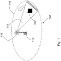
- FIG. 1 depicts a cellular communications network 100 in which embodiments herein may be implemented.
- the cellular communications network 100 is a cellular communication network such as an LTE, WCDMA, GSM network, any 3GPP cellular network, or any cellular network or system.
- the cellular communications network 100 comprises a base station 110.
- the base station 110 is a radio base station serving a cell 115.
- the base station 110 may e.g. be a radio base station such as an eNB, eNodeB, or a Home Node B, a Home eNode B, a GSM/EDGE radio base station or any other network unit capable to serve a user equipment or a machine type communication device in a cellular communications system.
- the base station 110 comprises a beam antenna 116.
- the beam antenna 116 is a dynamically directional antenna arrangement comprising one or more antennas or antenna elements, which may be dynamically controlled to radiate greater power in one or more directions, the so-called beam 117, allowing for increased performance on transmit and receive and reduced interference from unwanted sources.
- the antenna beam 117 is directed such that it provides coverage of different places in the cell 115 at different time periods. According to embodiments herein this may e.g. be performed by continuously sweeping a 360° lap regularly in time with or without a time interval between each lap, and/or by stepwise covering a 360° lap with a specific angle in every step. In some embodiments the beam 117 is not monotonically moved in the same angular rotation direction in the horizontal plane, but the location covered by the beam 117 may essentially hop between different locations according to a regular pattern or an irregular pattern, e.g. governed by a pseudo random sequence, as long as the beam's appearance in each location is predictable. In some embodiments a second beam 118 is used. How this is performed will be described more in detail below. (The second beam is shown in Figure 5 .)
- a communication device 120 is located within the cell 115.
- the communication device 120 is configured to communicate within the cellular communications network 100 via the base station 110 over a radio link 130 when the communication device 120 is present in the cell 115 served by the base station 110.
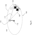
- a number of other communication devices may also be located within the cell 115, for example a second communication device 121 and a third communication device 122. These are described below and shown in respective Figures 5 and 6 .
- the communication device 120 may be a machine type communication device, i.e. a small autonomous device, such as e.g. a machine-to-machine communication device, a machine device which typically, more or less infrequently, e.g. once per week to once per minute, transmits and receives only small amounts of data.
- a machine type communication device i.e. a small autonomous device, such as e.g. a machine-to-machine communication device, a machine device which typically, more or less infrequently, e.g. once per week to once per minute, transmits and receives only small amounts of data.
- the communication device 120 may also be a user equipment such as e.g. a mobile terminal or a wireless terminal, a mobile phone, a computer such as e.g. a laptop, Personal Digital Assistant (PDA), or any other radio network unit capable to communicate over a radio link in a cellular communications system.
- a user equipment such as e.g. a mobile terminal or a wireless terminal
- a mobile phone e.g. a mobile phone
- a computer such as e.g. a laptop, Personal Digital Assistant (PDA), or any other radio network unit capable to communicate over a radio link in a cellular communications system.
- PDA Personal Digital Assistant
- the other communication devices for example the second communication device 121 and the third communication device 122 may be of any kind as described above.
- the communication device 120 is present in the cell 115 served by the base station 110 and is to start or later on perform some communication with the wireless communication network 100 via the base station 110.
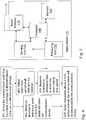
- Embodiments of a method in the communication device 120 for reducing power consumption in the communication device 120 will now be described with reference to the flowchart depicted in Figure 2 .
- the communication device 120 and the base station 110 are comprised in a cellular communications network 100.
- the communication device 120 may be represented by a MTC device or a user equipment.
- the method comprises the following actions, which actions may as well be carried out in another suitable order than described below.
- the communication device 120 obtains information about an antenna beam 117 of the base station 110.
- the beam 117 will be perceived by the communication device 120 in time periods.
- the information relates to when in time a time period starts and the duration of the time period.
- the obtaining of the information about the antenna beam 117 is performed by receiving information from the base station 110 about the communication device 120 being scheduled a Discontinuous Reception (DRX) cycle and/or a Discontinuous Transmission, (DTX) cycle, such that a passive part of the DRX or DTX cycle occurs when being out of the time period. I.e. in this way the information is obtained implicit.
- DRX means that the communication device 120 is configured with cyclically reoccurring alternating periods, where the communication device 120 may receive dedicated transmissions from the base station 110 during one period, the active part of the DRX cycle, but may not receive dedicated transmissions during the next period, the passive part of the DRX cycle.
- a DRX cycle thus comprises two periods respectively constituting an active part and a passive part, or vice versa.
- the communication device 120 has to monitor the appropriate radio channel(s) in order to be able to receive potential transmissions intended for the communication device 120.
- the communication device 120 do not have to monitor any radio channel(s) and may thus turn off its receiver circuitry and optionally enter a sleep mode in order to save energy.
- DTX is defined similarly, but instead of providing periods where the communication device 120 alternately may and may not receive dedicated transmissions, DTX configuration provisions periods where the communication device 120 alternate between being allowed to transmit and not being allowed to transmit.
- the obtaining of the information about the antenna beam 117 is performed by receiving information from the base station 110 about the communication device 120 being scheduled pre-allocated resources for uplink or downlink transmission such that the pre-allocated resources are scheduled to occur when being within the time period. I.e. also in this way the information is obtained implicit.
- the pre-allocated uplink resources shall be synchronized with the beam.
- the pre-allocation may e.g. be in the form of semi-persistent scheduling.
- a base station does not schedule every transmission/reception occasion, e.g. in the form of a time and frequency resource, but rather schedules a periodically reoccurring resource, or pattern of resources, for transmission or reception for the communication device.
- the information comprises that the beam 117 will be perceived by the communication device 120 in time periods.
- the information relating to when in time a time period starts and the duration of the time period is obtained by measuring conditions of the channel.
- the communication device 120 may measure the channel conditions, e.g. based on the quality of a received reference signal.
- the communication device 120 will detect a periodically reoccurring improvement of the channel conditions, coinciding with the beam 117 covering the location of the communication device120. In this way the communication device 120 may autonomously learn the periodicity of the beam pattern and/or the points in time when the communication device 120 may expect to be covered by the beam 117, as well as the duration of periods of coverage.
- the obtaining of information about the antenna beam 117 of the base station 110 may be performed by receiving from the base station 110, information about the periodicity of the time period.
- the information of when in time a time period starts and the duration of the time period may be obtained by measuring a time period when it occurs.
- a hybrid of timing of the predictable antenna beam 117and an autonomous detection of the beam may be provided, if the base station 110 informs the communication device 120 of the periodicity of the beam 117, i.e. the period with which the beam will reappear in the same direction, or cover the same location, while the communication device 120 itself is responsible for detecting at what time(s) during a period the antenna beam 117 is directed towards the communication device 120, i.e. the "phase" of the antenna beam movement.
- the communication device 120 may learn this from measuring the channel conditions, e.g. measuring a downlink reference signal sent from the base station 110. The measurements may be made less and less frequent, as the resulting conclusion on the beam timing becomes more reliable and accurate.
- the communication device 120 may learn both periodicity and phase autonomously and gradually rely more on the learnt timing. This feature may also comprise that the communication device 120 informs the base station 110 of its beam timing measurements, so that the base station may configure the communication device 120 with a matching DRX cycle. This feature of autonomous learning of the predictable antenna beam 117 relieves the base station 110 from having to measure the direction of the MTC devices.
- the obtaining of information about an antenna beam 117 of the base station 110 is performed by obtaining the information from the base station 110.
- a threshold on the channel quality required for uplink transmission may be set such that the time when the threshold value is exceeded, coincides with the start in time of the time period and the duration of the time period. Setting a threshold on the channel quality required for uplink transmission for the communication device 120 is one way of avoiding wasting power on unnecessarily high power transmissions. Combining this with an occasionally appearing antenna beam 117 will achieve a power efficient transmission, since the threshold may be set so that it essentially only is exceeded when the communication device 120 is covered by the antenna beam 117.
- the communication device 120 may estimate the channel conditions from a downlink beam-formed reference signal or feedback from the base station 110 on uplink reference signals. Also this feature of autonomous detection of the predictable antenna beam 117 relieves the base station from having to measure the direction of the communication device 120. With this mechanism the antenna beam 117 does not have to be predictable, as the channel quality threshold takes care of synchronizing the communication devices' 120 transmissions with the antenna beam 117. The feature may however still be combined with a predictably occurring beam, providing the advantage that the communication device 120 only has to check for transmission opportunities when it is covered by the beam.
- the communication device 120 When the communication device 120 is out of the time period, it refrains from attempting to receive or transmit data using the antenna beam 117. This action is performed deliberately. During the refraining no power is consumed for attempting to receive or transmit data using the antenna beam 117.
- the communication device 120 When the communication device 120 is within the time period, it receives or transmits data from or to the base station 110 over a channel using the antenna beam 117.
- the communication device 120 is covered by the antenna beam 117 not only at a predictable time but also for a predictable time period. Hence, the communication device 120 would preferably complete an entire communication event during this time period. Whether this is possible depends largely on the amount of data to transmit during a communication event and the number of message exchanges in uplink and downlink e.g. between the communication device 120 and an application server, but it may also be affected by buffer status reports from the communication device 120 to the base station 110 and scheduling decisions in the base station 110.
- the communication device 120 when the communication device 120 has not completed a communication event by receiving or transmitting data from or to the base station 110 when being within one time period.
- the communication device 120 may then perform any of the Actions 204 or 205.
- the communication device 120 may return to an idle state until a subsequent time period wherein the antenna beam 117 will be perceived by the communication device 120, and when the subsequent time period occurs, continue the communication event.
- the communication device 120 may remain in a connected state, and when the subsequent time period occurs, continue the communication event.
- the communication device 120 may further stay in connected state and continue communicating without beam coverage, and thus with worse radio conditions, until the communication event is complete.
- the base station 110 may facilitate completion of the communication event by using beam-forming towards the communication device 120 whenever it is scheduled, even after the "general beam” has seized to cover the communication device 120.
- the communication device 120 comprises the following arrangement depicted in Figure 3 .
- the communication device 120 and the base station 110 are comprised in the cellular communications network 100.
- the communication device 120 may e.g. be represented by a MTC device or a user equipment.
- the communication device 120 comprises an obtaining unit 310 configured to obtain information about the antenna beam 117 of the base station 110.
- the antenna beam 117 will be perceived by the communication device 120 in time periods.
- the information relates to when in time a time period starts and the duration of the time period.
- the obtaining unit 310 is further configured to obtain information about the antenna beam 117 by receiving information from the base station 110 about the communication device 120 being scheduled a Discontinuous Reception, DRX, cycle and/or a Discontinuous Transmission, DTX, cycle such that a passive part of the DRX or DTX cycle occurs when being out of the time period.
- DRX Discontinuous Reception
- DTX Discontinuous Transmission
- the obtaining unit 310 is further configured to obtain information about an antenna beam 117 by receiving information from the base station 110 about the communication device 120 being scheduled pre-allocated resources for uplink or downlink transmission such that the pre-allocated resources are scheduled to occur when being within the time period.
- the obtaining unit 310 may further be configured to obtain information about an antenna beam 117 of the base station 110 by obtaining information that the antenna beam 117 will be perceived by the communication device 120 in time periods.
- the information relating to when in time a time period starts and the duration of the time period is obtained by measuring conditions of a channel.
- the obtaining unit 310 may further be configured to obtain information about the antenna beam 117 of the base station 110 by receiving from the base station 110 information about the periodicity of the time period.
- the information of when in time a time period starts and the duration of the time period may be obtained by measuring a time period when it occurs.
- the obtaining unit 310 may further be configured to obtain information about an antenna beam 117 of the base station 110 by obtaining the information from the base station 110.
- a threshold of the channel quality required for uplink transmission is set such that the time when the threshold value is exceeded, it coincides with the start in time of the time period and the duration of the time period.
- the communication device 120 further comprises a processing unit 320 configured to refrain from attempting to receive or transmit data using the antenna beam 117 when being out of the time period, during which refraining no power is consumed for attempting to receive or transmit data using the antenna beam 117.
- the communication device 120 may further comprise a transceiver 330 configured to receive or transmit data from or to the base station 110 over the channel using the antenna beam 117, when being within the time period.
- a transceiver 330 configured to receive or transmit data from or to the base station 110 over the channel using the antenna beam 117, when being within the time period.
- the processing unit 320 when the transceiver 330 in the communication device 120 has not completed a communication event by receiving or transmitting data from or to the base station 110 when being within one time period, the processing unit 320 further is configured to return to an idle state until a subsequent time period wherein the antenna beam 117 will be perceived by the communication device 120, and when the subsequent time period occurs, continuing the communication event. Or as an alternative, the processing unit 320 may further be configured to remain in a connected state, and when the subsequent time period occurs, continue the communication event. Please note that this feature may be combined with any suitable embodiment above.
- the embodiments of the communication device 120 for reducing power consumption in the communication device 120 may be implemented through one or more processors, such as the processing unit 320 in communication device 120 depicted in Figure 3 , together with computer program code for performing the actions of the embodiments herein.
- the program code mentioned above may also be provided as a computer program product, for instance in the form of a data carrier carrying computer program code for performing the embodiments herein when being loaded into communication device 120.
- a data carrier may be in the form of a CD ROM disc. It is however feasible with other data carriers such as a memory stick.
- the computer program code may furthermore be provided as pure program code on a server and downloaded to the communication device 120, e.g. remotely.
- the communication device 120 may further comprise a memory 340 comprising one or more memory units.
- the memory 350 is arranged to be used to store data such as information about the antenna beam 117, the threshold of the channel quality required for uplink transmission, schedulings, and applications to perform the actions of the embodiments herein when being executed in the communication device 120.
- Embodiments of a method in the base station 110 for enabling reduction of power consumption in a communication device 120 will now be described with reference to the flowchart depicted in Figure 4 .
- the communication device 120 and the base station 110 are comprised in a cellular communications network 100.
- the base station 110 serves a cell 115 comprising the communication device 120.
- a second communication device is located in the cell 115 and a second antenna beam 118 is used.
- the method comprises the following actions, which actions may as well be carried out in another suitable order than described below.
- the base station 110 directs the antenna beam 117 such that it provides coverage of different places in the cell 115 in different time periods.
- This action 401 may be performed by continuously sweeping a 360° lap regularly in time with or without a time interval between each lap. For example this may be performed by continuously sweeping a 360° lap once every X seconds, with Y seconds between laps.
- X may e.g. be in the order of 10 seconds or 60 seconds.
- Y may e.g. be in the order of 10 seconds or 120 seconds.
- This action 401 may further be performed by stepwise covering a 360° lap with a specific angle in every step.
- this may be performed by stepwise coverage of a 360° lap with Z° in every step.
- Z may e.g. be in the order of 10°.
- the beam 117 is not monotonically moved in the same angular rotation direction in the horizontal plane, but the location covered by the beam 117 may essentially hop between different locations according to a regular pattern or an irregular pattern, e.g. governed by a pseudo random sequence, as long as the beam's appearance in each location is predictable.
- This action 401 may further be performed by moving the beam 117 to subsequently cover different locations according to a regular or irregular pattern, providing predictable appearance of the beam 117 in each covered location.
- This action 401 may also be performed by directing the antenna beam 117 according to a scheme such that the communication device 120 is out of the time period when a passive part of a DRX and/or DTX cycle of the communication device 120 occurs, by using spatial coordination of the antenna beam 117 and the direction of the communication device 120.
- the "lap-wise" coverage may be replaced by any scheme that matches time-wise distributed DRX and DTX cycles or explicitly signalled beam coverage periods with spatial coordination of antenna beam 117 and the communication device's 120 direction. This eliminates the need for specific communication device 120 functionality.
- a second communication device 121 is located in the cell 115 and a second antenna beam 118 is used within the base station 110.
- the second antenna beam 118 may be directed such that it in second time periods provides coverage of a place in the cell 115 where the second communication device 121 is located.
- the base station 110 may maintain multiple uplink receive beams 117, 118 simultaneously, thereby being able to cover communication devices 120 and 121 in several directions simultaneously.
- the base station 110 may utilize this ability to increase the fraction of time that each communication device, for which the uplink beam provides a significant benefit, is covered by the uplink beam, thereby giving the communication devices 120 and 121 more opportunities to transmit with enhanced conditions.
- the base station 110 may also employ a similar scheme to use two or more downlink transmit beams to simultaneously provide coverage in multiple locations, e.g. covering multiple communication devices, such as communication device 120 and 121.
- the base station 110 may be able to cover all the relevant communication devices with uplink beams and/or downlink beams simultaneously, thereby allowing them to transmit and/or receive with enhanced conditions at any time.
- the multiple uplink beams 117, 118 do not have to be synchronized with simultaneous multiple downlink beams, and/or downlink beams as the base station 110 knows when it has something to send in the downlink. However, whenever the base station 110 has something to send to one of the communication devices 120 and 121, such as the communication device 120 benefitting significantly from beam-forming, e.g. in response to a received UL transmission, the base station 110 may utilize downlink beam-forming towards the targeted communication device 120.
- this may mean that the base station 110 tries a large number of different combining weight configurations, for each configuration attempting to detect and decode the communication device signal.
- the combining weights are complex weight factors used when processing the signals received at different antennas or antenna elements, determining the weight to be given to each received signal when combining all the received signals.
- a combining weight configuration is a defined set of such combining weights, one for each receiving antenna or antenna element.
- the transmit timing is decoupled from the communication devices' locations.
- a possible way to deal with the potentially large consumption of processing power that this may cause may be that the base station 110 buffers the signal and processes it sequentially, at the cost of introducing some delay.
- the processing may include "all" possible weight configurations, or a subset based on likely locations of communication devices.
- a third communication device 122 is also located in the cell 115.
- the antenna beam 117 may be shaped such that it will be perceived by both the communication device 120 and the third communication device 122 in the same time periods. These embodiments are shown in Figure 6 . I.e. through advanced beam shape control the base station may tailor the beam shape to cover a number of communication devices 120, 121 with known locations at a time. The antenna beam 117 may be continuously reshaped to cover new sets of communication devices 120, 121 in a repetitive, or otherwise predictable, fashion.
- the base station 110 may utilize the horizontal dimension when directing the antenna beam 117. In addition to the horizontal direction, the base station 110 may utilize the vertical dimension when directing the antenna beam 117, thus providing even more accurately targeting of different locations.
- the beam may further be configured as a separate cell, e.g. "on top of" the regular cell 115.
- the communication device 120 may switch to an overlapping regular cell such as cell 115.
- the antenna beam 117 is predictable or not, whether provided in a separate cell 115 or not, the resulting occasional radio coverage, or occasionally improved radio conditions, is a way to make the system more energy efficient than with continuous coverage.
- embodiments herein may be achieved by leveraging current state of the art and future advanced or Reconfigurable Antenna Systems (RAS) that offer flexible possibilities in terms of tailoring dynamic antenna properties.
- RAS Reconfigurable Antenna Systems
- the base station may also utilize cell specific features, changing the properties of the entire cell 115, rather than features targeting specific communication devices or sets of communication devices. For instance, instead of letting the antenna beam 117 sweep or otherwise move around to temporarily provide improved conditions in different locations the base station 110 may utilize advanced and/or reconfigurable antenna features, e.g. electronically (i.e. non-mechanically) controlled instantaneous antenna tilt changes, to temporarily increase the range of the cell 115 and thus improve the radio conditions at the cell 115 edge. As previously described in conjunction with beam forming, this would occur at periodic or otherwise predictable time instants, optionally synchronized with DRX cycles of concerned communication devices, in order to allow efficient utilization of the improved conditions.
- advanced and/or reconfigurable antenna features e.g. electronically (i.e. non-mechanically) controlled instantaneous antenna tilt changes
- Another option would be to stepwise change the antenna tilt and combine this with vertical and/or horizontal angle beam-forming, in order to provide improved conditions in a circle sector shaped band, with limited radius interval, area at a certain distance from the base station 110, wherein the distance depends on the tilt and changes as the tilt changes.
- the information relating to when in time a time period starts and the duration of the time period is obtained by the base station 110.
- the base station may e.g. measure the direction to the communication device 120 to determine when in time the antenna beam 117 will cover the location of the communication device 120.
- the information relating to when in time a time period starts and the duration of the time period is also obtained by the base station 110.
- the base station 110 selects when in time the time period shall start and the duration the time period shall have.
- the base station 110 measures the direction to the communication device 120 to determine which direction to direct the antenna beam 117 to during the selected time period.
- the base station 110 may first select 403 a suitable point or suitable points in time when the communication device 120 should be covered by the beam 117 and then, after measuring 403 the direction to the communication device 120, determine to direct the beam in the measured direction at the selected point in time or points in time.
- the base station 110 may inform the communication device 120 of the timing of the antenna beam 117 at the communication device's location, so that the communication device 120 may synchronize its unscheduled UL transmissions, e.g. scheduling request and random access with the antenna beam 117.
- a scheduling request is a signaling message or indication that a communication devices sends to a base station to request allocation of transmission resources for uplink transmission.
- random access is a procedure used by a communication device to establish an initial contact with a base station and to synchronize the communication device's uplink transmissions. Before establishing this contact through a random access procedure the communication device cannot request allocation of uplink transmission resources.
- a communication device may also use a random access procedure, even when a contact with the base station is established, in order to resynchronize its uplink transmissions.
- the base station 110 sends information about the antenna beam 117 to the communication device 120.
- the antenna beam 117 will be perceived by the communication device 120 in time periods.
- the information relates to when in time a time period starts and the duration of the time period.
- the information received by the communication device 120 enables the communication device 120 when being out of a time period, to refrain from attempting to receive or transmit data using the antenna beam 117. During the refraining no power is consumed for attempting to receive or transmit data using the antenna beam 117.
- the sending the information about the antenna beam 117 is performed by sending information about scheduling of a DRX cycle and/or a DTX cycle, which is performed such that a passive part of the DRX and/or DTX cycle occurs when the communication device 120 is out of the time period.
- the sending of the information about the antenna beam 117 is performed by sending information to the communication device 120 about scheduling pre-allocated resources for the communication device 120 for uplink or downlink transmission such that the pre-allocated resources occurs when being within the time period.
- the base station 110 comprises the following arrangement depicted in Figure 7 .
- the communication device 120 and the base station 110 are comprised in the cellular communications network 100.
- the base station 110 serves a cell 115 comprising the communication device 120.
- the base station 110 comprises a beam antenna 710 configured to direct the antenna beam 117 such that it provides coverage of different places in the cell 115 in different time periods.
- the beam antenna is a dynamically directional antenna arrangement comprising one or more antennas or antenna elements.
- the beam antenna 710 is further configured to direct the antenna beam 117 such that it provides coverage of different places in the cell 115 in different time periods by any of:
- a second antenna beam 118 is used.
- the beam antenna 710 is further configured to direct the second antenna beam 118 such that it in second time periods provides coverage of a place in the cell 115 where the second communication device 121 is located. Please note that this feature may be combined with any suitable embodiment above.
- a third communication device 122 is located in the cell 115.
- the beam antenna 710 may further be configured to shape the antenna beam 117 such that it will be perceived by both the communication device 120 and the third communication device 122 in the same time periods. Please note that this feature may be combined with any suitable embodiment above, also the embodiments using a second antenna beam 118.
- the base station 110 further comprises a sending unit 720 configured to send information about the antenna beam 117 to the communication device 120.
- the antenna beam 117 will be perceived by the communication device 120 in time periods.
- the information relates to when in time a time period starts and the duration of the time period. This enables the communication device 120 when being out of a time period, to refrain from attempting to receive or transmit data using the antenna beam 117, during which refraining no power is consumed for attempting to receive or transmit data using the antenna beam 117.
- the sending unit 720 is further configured to send to the communication device 120 information about the antenna beam 117 by sending information about scheduling a Discontinuous Reception , DRX, cycle and/or a Discontinuous Transmission, DTX, cycle such that a passive part of the DRX and/or DTX cycle occurs when the communication device 120 is out of the time period.
- the sending unit 720 is further configured to send information about the antenna beam 117 by sending information to the communication device 120 about scheduling pre-allocated resources for the communication device 120 for uplink or downlink transmission such that the pre-allocated resources occur when being within the time period.
- the base station 110 further comprises a measuring unit 730 configured to measure a direction to the communication device 120 to determine when in time the antenna beam 117 will cover the location of the communication device 120. The measurement is performed to obtain the information relating to when in time a time period starts and the duration of the time period.
- the base station 110 further comprises a processor 740 configured to select when in time the time period shall start and the duration the time period shall have.
- the measuring unit 730 may be configured to measure a direction to the communication device 120 to determine which direction to direct the antenna beam 117 to during the selected time period.
- the embodiments of the base station 110 for enabling reduction of power consumption in a communication device 120 may be implemented through one or more processors, such as the processor 740 in the communication device 120 depicted in Figure 7 , together with computer program code for performing actions of the embodiments herein.
- the program code mentioned above may also be provided as a computer program product, for instance in the form of a data carrier carrying computer program code for performing the embodiments herein when being loaded into the base station 110.
- One such carrier may be in the form of a CD ROM disc. It is however feasible with other data carriers such as a memory stick.
- the computer program code may furthermore be provided as pure program code on a server and downloaded to the base station 110.
- the base station 110 may further comprise a memory 750 comprising one or more memory units.
- the memory 750 is arranged to be used to store data such as measurements such as measurements of the direction to the communication device 120 to determine when in time the antenna beam 117 will cover the location of the communication device 120, directions of antenna beams, information relating to when in time a time period starts and the duration of the time period, schedulings, program code and applications to perform the actions of the embodiments herein when being executed in the base station 110.
- the communication device 120 may efficiently utilize the improved conditions for uplink transmissions, especially when the communication device is represented by a MTC devices running time tolerant applications, depending on how frequently the beam appears.
- the base station 110 may coordinate its downlink transmissions with the antenna beam 117.
- the "lap-wise" coverage may be replaced by any scheme that matches time-wise distributed DRX and/or DTX cycles or explicitly signalled beam coverage periods with spatial coordination of the antenna beam 117 and communication device direction.
- more demanding communication devices such as MTC devices, in terms of traffic volume or delay sensitivity, may be targeted more frequently by the antenna beam 117 then less demanding communication devices.
- more demanding communication devices such as MTC devices, in terms of traffic volume or delay sensitivity, may be scheduled with DRX and/or DTX duty cycles having a larger fraction of active time than less demanding devices.
- directions where more communication devices such as MTC devices are located may be targeted more frequently or for longer time periods than other directions.
- the base station 110 may schedule DRX and/or DTX cycles for the communication device 120 or explicitly inform the communication device 120 of the 360° coverage periods, so that its active periods coincide with an entire 360° coverage sequence.
- the communication device 120 will not as easily be able to benefit from the antenna beam 117 for unsolicited uplink transmissions, as it only has a very coarse knowledge of when the antenna beam 117 will actually cover its location. This may be mitigated by synchronizing the downlink and uplink beam-forming so that the communication device 120 may indirectly detect the presence of the uplink beam from downlink signal, e.g. reference symbols, quality measurements.
- the beam-forming schemes described above may imply the following receiver side behavior at the base station 110:
- the base station 110 estimates the uplink channel from the communication device 120 based on a known reference signal which the communication device 120 transmits at a known time. The base station 110 then performs the beam-forming by selecting the combining weights based on the channel estimation.
- the base station 110 processes multiple simultaneous receive beams, targeting multiple communication devices in different directions simultaneously. This variation has previously been described.
- the communication devices such as communication device 120, the second communication device 121, and the third communication device 122 may efficiently utilize the improved conditions for uplink transmissions, in particular communication devices running time tolerant applications, depending on how frequently the beam appears.
- the base station may coordinate its downlink transmissions with the antenna beam.
- the communication devices such as communication device 120, the second communication device 121, and the third communication device 122, may be synchronized with the antenna beam through DRX cycles and/or DTX cycles, or autonomous self learning.
Landscapes
- Engineering & Computer Science (AREA)
- Computer Networks & Wireless Communication (AREA)
- Signal Processing (AREA)
- Mobile Radio Communication Systems (AREA)
Claims (15)
- Verfahren bei einem Kommunikationsgerät (120) zur Senkung des Energieverbrauchs beim Kommunikationsgerät (120), wobei das Kommunikationsgerät (120) und eine Basisstation (110) in einem zellularen Kommunikationsnetzwerk (100) umfasst sind, wobei das Verfahren Folgendes umfasst:Messen von mindestens einer Antennenstrahlzeitsteuerung auf Grundlage von Erkennen eines Kanalzustandes,Erhalten (201) von Informationen über einen Antennenstrahl (117) der Basisstation (110), wobei der Antennenstrahl (117) über eine dynamische Richtantennenanordnung dynamisch gesteuert wird, wobei das Kommunikationsgerät (120) die Basisstation (110) über die gemessene mindestens eine Antennenstrahlzeitsteuerung informiert, sodass der Antennenstrahl (117) durch die Basisstation (110) auf Grundlage der gemessenen mindestens einen Antennenstrahlzeitsteuerung konfiguriert wird, wobei der Antennenstrahl (117) durch das Kommunikationsgerät (120) in Zeiträumen erkannt wird, wobei sich die Informationen darauf beziehen, zu welchem Zeitpunkt ein Zeitraum der Zeiträume beginnt, sowie auf eine Dauer des Zeitraumes,wobei das Erhalten (201) von Informationen über den Antennenstrahl (117) der Basisstation (110) durch Erhalten von Informationen von der Basisstation (110) durchgeführt wird, und wobei ein Schwellenwert für eine Kanalqualität, die zur Aufwärtsübertragung nötig ist, so eingestellt ist, dass für eine Zeitdauer, in der der Schwellenwert übertroffen wird, das Kommunikationsgerät (120) durch den Antennenstrahl (117) abgedeckt wird,Unterlassen (202) eines Versuches, Daten unter Verwendung des Antennenstrahls (117) auf Grundlage der erhaltenen Informationen außerhalb der Zeiträume zu empfangen oder zu übermitteln, wobei während des Unterlassens kein Strom beim Versuch, Daten unter Verwendung des Antennenstrahls (117) zu empfangen oder zu übermitteln, verbraucht wird.
- Verfahren nach Anspruch 1, wenn Empfangen oder Übertragen (203) von Daten von oder an die Basisstation (110) über einen Kanal unter Verwendung des Antennenstrahls (117) innerhalb des Zeitraumes liegt.
- Verfahren nach einem der Ansprüche 1 - 2, wobei das Erhalten (201) von Informationen über einen Antennenstrahl (117) durchgeführt wird durch Empfangen von Informationen von der Basisstation (110) über das Einplanen für das Kommunikationsgerät eines diskontinuierlichen Empfangszyklus, DRX-Zyklus, und/oder eines diskontinuierlichen Übertragungszyklus, DTX-Zyklus, sodass ein passiver Teil des DRX- oder des DTX-Zyklus außerhalb der Zeiträume erfolgt, wobei das Kommunikationsgerät (120) während des passiven Teils des DRX- oder des DTX-Zyklus den Versuch unterlässt, Daten unter Verwendung des Antennenstrahls (117) zu empfangen oder zu übertragen.
- Verfahren nach einem der Ansprüche 1 - 2, wobei das Erhalten (201) von Informationen über einen Antennenstrahl (117) durchgeführt wird durch Empfangen von Informationen von der Basisstation (110) über das Einplanen für das Kommunikationsgerät (120) von vorab zugewiesenen Ressourcen für Aufwärts- oder Abwärtsübertragungen, sodass die vorab zugewiesenen Ressourcen so eingeplant sind, dass sie erfolgen, wenn sie innerhalb des Zeitraumes liegen.
- Verfahren nach einem der Ansprüche 2 - 4, wobei das Kommunikationsgerät (120), wenn es innerhalb eines Zeitraums liegt, ein Kommunikationsereignis nicht durch Empfangen oder Übertragen (203) von Daten von oder an die Basisstation (100) abgeschlossen hat, eines von Folgendem durchführt:Zurückkehren (204) in einen Ruhezustand bis zu einem darauffolgenden Zeitraum, in dem der Antennenstrahl (117) durch das Kommunikationsgerät (120) erkannt wird, und, wenn der darauffolgende Zeitraum erfolgt, Fortsetzen des Kommunikationsereignisses; oderVerbleiben (205) in einem verbundenen Zustand, und, wenn der darauffolgende Zeitraum erfolgt, Fortsetzen des Kommunikationsereignisses.
- Verfahren in einer Basisstation (110) zum Ermöglichen einer Senkung des Energieverbrauches bei einem Kommunikationsgerät (120), wobei das Kommunikationsgerät (120) und die Basisstation (110) in einem zellularen Kommunikationsnetzwerk (100) umfasst sind, und wobei die Basisstation (110) eine Zelle (115) versorgt, die das Kommunikationsgerät (120) umfasst, wobei das Verfahren Folgendes umfasst:Ausrichten (401) eines Antennenstrahls, sodass er Abdeckung von verschiedenen Orten in der Zelle (115) zu verschiedenen Zeiträumen bereitstellt, wobei der Antennenstrahl (117) über eine dynamische Richtantennenanordnung dynamisch gesteuert wird, wobei der Antennenstrahl (117) auf Grundlage von Messungen von mindestens einer Antennenstrahlzeitsteuerung auf Grundlage von Erkennen eines Kanalzustands konfiguriert wird, die vom Kommunikationsgerät (120) durchgeführt und an die Basisstation (110) kommuniziert werden,Senden (405) von Informationen über den Antennenstrahl (117) an das Kommunikationsgerät (120), wobei der Antennenstrahl (117) durch das Kommunikationsgerät (120) in Zeiträumen erkannt wird, wobei sich die Informationen darauf beziehen, zu welchem Zeitpunkt ein Zeitraum der Zeiträume beginnt, sowie auf die Dauer des Zeitraumes, wobei ein Schwellenwert für eine Kanalqualität, die für Aufwärtsübertragungen nötig ist, so eingestellt ist, dass für eine Zeitdauer, in der der Schwellenwert übertroffen wird, das Kommunikationsgerät (120) durch den Antennenstrahl (117) abgedeckt wird,Ermöglichen, dass das Kommunikationsgerät (120) den Versuch unterlässt, Daten unter Verwendung des Antennenstrahls (117) auf Grundlage der gesendeten Informationen außerhalb der Zeiträume zu empfangen oder zu übermitteln, wobei während des Unterlassens kein Strom beim Versuch, Daten unter Verwendung des Antennenstrahls (117) zu empfangen oder zu übermitteln, verbraucht wird.
- Verfahren nach Anspruch 6, wobei das Senden (405) von Informationen über den Antennenstrahl (117) durchgeführt wird durch Senden von Informationen über das Einplanen eines diskontinuierlichen Empfangszyklus, DRX-Zyklus, und/oder eines diskontinuierlichen Übertragungszyklus, DTX-Zyklus, sodass ein passiver Teil des DRX- oder des DTX-Zyklus erfolgt, wenn das Kommunikationsgerät (120) außerhalb der Zeiträume liegt, wobei das Kommunikationsgerät (120) während des passiven Teils des DRX- oder des DTX-Zyklus den Versuch unterlässt, Daten unter Verwendung des Antennenstrahls (117) zu empfangen oder zu übertragen.
- Verfahren nach Anspruch 6, wobei das Senden (405) von Informationen über den Antennenstrahl (117) durchgeführt wird durch Senden von Informationen an das Kommunikationsgerät (120) über das Einplanen für das Kommunikationsgerät (120) von vorab zugewiesenen Ressourcen für Aufwärts- oder Abwärtsübertragungen, sodass die vorab zugewiesenen Ressourcen erfolgen, wenn sie innerhalb des Zeitraumes liegen.
- Verfahren nach einem der Ansprüche 6 - 8, wobei die Informationen in Bezug auf den Zeitpunkt, zu dem ein Zeitraum beginnt, sowie auf eine Dauer des Zeitraumes erhalten werden durch
Messen (402) der Ausrichtung zum Kommunikationsgerät (120), um zu bestimmen, zu welchem Zeitpunkt der Antennenstrahl (117) einen Ort des Kommunikationsgerätes (120) abdeckt. - Verfahren nach einem der Ansprüche 6 - 8, wobei die Informationen in Bezug auf den Zeitpunkt, zu dem ein Zeitraum beginnt, sowie auf eine Dauer des Zeitraumes erhalten werden durch
Auswählen (403), zu welchem Zeitpunkt der Zeitraum beginnen soll, sowie der Dauer, die der Zeitraum haben soll, und
Messen (404) der Ausrichtung zum Kommunikationsgerät (120), um zu bestimmen, in welche Ausrichtung der Antennenstrahl (117) während des ausgewählten Zeitraumes auszurichten ist. - Verfahren nach einem der Ansprüche 6 - 10, wobei das Ausrichten (401) eines Antennenstrahls (117), sodass er in verschiedenen Zeiträumen Abdeckung von verschiedenen Orten in der Zelle (115) bereitstellt, durch eines von Folgendem durchgeführt wird:durchgehendes Abtasten einer 360°-Runde regelmäßig innerhalb der Zeit mit oder ohne ein Zeitintervall zwischen jeder Runde, und/oderschrittweises Abdecken einer 360°-Runde mit einem bestimmten Winkel in jedem Schritt, und/oderBewegen des Antennenstrahls (117), um nachfolgend verschiedene Orte gemäß einem regelmäßigen oder unregelmäßigen Muster abzudecken, wobei ein vorhersehbares Auftauchen des Antennenstrahls (117) an jedem abgedeckten Ort bereitgestellt wird, und/oderAusrichten des Antennenstrahls (117) gemäß einem Schema, sodass sich das Kommunikationsgerät (120) außerhalb der Zeiträume befindet, wenn ein passiver Teil eines DRX- und/oder eines DTX-Zyklus des Kommunikationsgerätes (120) erfolgt, unter Verwendung von räumlicher Koordination des Antennenstrahls (117) und der Ausrichtung des Kommunikationsgerätes (120), wobei das Kommunikationsgerät (120) während eines passiven Teiles des DRX- oder des DTX-Zyklus den Versuch unterlässt, Daten unter Verwendung des Antennenstrahls (117) zu empfangen oder zu übertragen.
- Verfahren nach einem der Ansprüche 6 - 11, wobei sich ein zweites Kommunikationsgerät (121) in der Zelle (115) befindet, wobei ein zweiter Antennenstrahl (118) verwendet wird, und wobei das Ausrichten (401) eines Antennenstrahls (117, 118) durchgeführt wird durch weiteres Ausrichten des zweiten Antennenstrahls (118), sodass er in zweiten Zeiträumen Abdeckung eines Ortes in der Zelle (115) bereitstellt, in der sich das zweite Kommunikationsgerät (121) befindet.
- Verfahren nach einem der Ansprüche 6 - 12, wobei sich ein drittes Kommunikationsgerät (122) in der Zelle (115) befindet, und wobei der Antennenstrahl (117) so geformt ist, dass er sowohl von dem Kommunikationsgerät (120) als auch dem dritten Kommunikationsgerät (122) in Zeiträumen erkannt wird.
- Kommunikationsgerät (120) zur Senkung des Energieverbrauches bei dem Kommunikationsgerät (120), wobei das Kommunikationsgerät (120) und eine Basisstation (110) in einem zellulären Kommunikationsnetzwerk (100) umfasst sind, wobei das Kommunikationsgerät (120) Folgendes umfasst:eine Erhaltungseinheit (310), die dazu konfiguriert ist, Informationen über einen Antennenstrahl (117) der Basisstation (110) zu erhalten, wobei der Antennenstrahl (117) über eine dynamische Richtantennenanordnung dynamisch gesteuert wird, wobei das Kommunikationsgerät (120) dazu konfiguriert ist, mindestens eine Antennenstrahlzeitsteuerung zu messen und die Basisstation (110) über die Messung zu informieren, sodass der Antennenstrahl (117) auf Grundlage der durch das Kommunikationsgerät (120) gemessenen mindestens einen Antennenstrahlzeitsteuerung konfiguriert (110) wird, wobei die Messung auf Erkennung eines Kanalzustandes basiert, wobei der Antennenstrahl (117) durch das Kommunikationsgerät (120) in Zeiträumen erkannt wird, wobei sich die Informationen darauf beziehen, zu welchem Zeitpunkt ein Zeitraum der Zeiträume beginnt, sowie auf die Dauer des Zeitraumes,wobei die Erhaltungseinheit ferner dazu konfiguriert ist, Informationen über den Antennenstrahl (117) durch Erhalten der Informationen von der Basisstation (110) zu erhalten, und wobei ein Schwellenwert für eine Kanalqualität, die zur Aufwärtsübertragung nötigt ist, so eingestellt ist, dass für eine Zeitdauer, in der der Schwellenwert übertroffen wird, das Kommunikationsgerät (120) durch den Antennenstrahl (117) abgedeckt wird,eine Prozessoreinheit (320), die dazu konfiguriert ist, den Versuch zu unterlassen, Daten unter Verwendung des Antennenstrahls (117), wenn außerhalb der Zeiträume liegend, auf Grundlage der erhaltenen Informationen zu empfangen oder zu übermitteln, wobei während des Unterlassens kein Strom beim Versuch, Daten unter Verwendung des Antennenstrahls (117) zu empfangen oder zu übertragen, verbraucht wird.
- Basisstation (110) zum Ermöglichen einer Senkung des Energieverbrauches bei einem Kommunikationsgerät (120), wobei das Kommunikationsgerät (120) und die Basisstation (110) in einem zellularen Kommunikationsnetzwerk (100) umfasst sind, und wobei die Basisstation (110) eine Zelle (115) versorgt, die das Kommunikationsgerät (120) umfasst, wobei die Basisstation (110) Folgendes umfasst:eine Strahlantenne (710), die dazu konfiguriert ist, den Antennenstrahl (117) so auszurichten, dass er Abdeckung für verschiedene Orte in der Zelle (115) zu verschiedenen Zeiträumen bereitstellt, wobei die Strahlantenne eine dynamische Richtantennenanordnung ist, die ein(e) oder mehrere Antennen oder Antennenelemente umfasst, wobei der Antennenstrahl (117) auf Grundlage von Messungen von mindestens einer Antennenstrahlzeitsteuerung auf Grundlage von Erkennen eines Kanalzustandes konfiguriert wird, die durch das Kommunikationsgerät (120) durchgeführt und an die Basisstation (110) kommuniziert werden,eine Sendeeinheit (720), die dazu konfiguriert ist, Informationen über den Antennenstrahl (117) an das Kommunikationsgerät (120) zu senden, wobei der Antennenstrahl (117) durch das Kommunikationsgerät (120) in Zeiträumen erkannt wird, wobei sich die Informationen darauf beziehen, zu welchem Zeitpunkt ein Zeitraum der Zeiträume beginnt, sowie auf die Dauer des Zeitraumes, wobei ein Schwellenwert für eine Kanalqualität, die zur Aufwärtsübertragung nötig ist, so eingestellt ist, dass für eine Zeitdauer, in der der Schwellenwert übertroffen wird, das Kommunikationsgerät (120) durch den Antennenstrahl (117) abgedeckt wird,Ermöglichen, dass das Kommunikationsgerät (120) den Versuch unterlässt, Daten unter Verwendung des Antennenstrahls (117), wenn außerhalb der Zeiträume liegend, auf Grundlage der gesendeten Informationen außerhalb der Zeiträume zu empfangen oder zu übermitteln, wobei während des Unterlassens kein Strom beim Versuch, Daten unter Verwendung des Antennenstrahls (117) zu empfangen oder zu übermitteln, verbraucht wird.
Applications Claiming Priority (1)
| Application Number | Priority Date | Filing Date | Title |
|---|---|---|---|
| PCT/SE2011/050218 WO2012115553A1 (en) | 2011-02-25 | 2011-02-25 | Method and arrangement for reducing power consumption in a communication device |
Publications (3)
| Publication Number | Publication Date |
|---|---|
| EP2679053A1 EP2679053A1 (de) | 2014-01-01 |
| EP2679053A4 EP2679053A4 (de) | 2016-08-10 |
| EP2679053B1 true EP2679053B1 (de) | 2017-11-01 |
Family
ID=46721106
Family Applications (1)
| Application Number | Title | Priority Date | Filing Date |
|---|---|---|---|
| EP11859111.4A Active EP2679053B1 (de) | 2011-02-25 | 2011-02-25 | Verfahren und vorrichtung zur senkung des energieverbrauches bei einem kommunikationsgerät |
Country Status (3)
| Country | Link |
|---|---|
| US (1) | US20130331081A1 (de) |
| EP (1) | EP2679053B1 (de) |
| WO (1) | WO2012115553A1 (de) |
Families Citing this family (25)
| Publication number | Priority date | Publication date | Assignee | Title |
|---|---|---|---|---|
| CN104335500B (zh) * | 2012-05-25 | 2018-11-06 | 三星电子株式会社 | 在使用波束形成的移动通信系统中发送和接收参考信号的方法和装置 |
| GB2507782B (en) * | 2012-11-09 | 2015-01-21 | Broadcom Corp | Methods and apparatus for wireless transmission |
| WO2014117855A1 (en) * | 2013-02-01 | 2014-08-07 | Telefonaktiebolaget L M Ericsson (Publ) | A method for alignment of multi-beam antennas in a non line-of-sight scenario |
| KR102026256B1 (ko) | 2013-05-21 | 2019-11-04 | 삼성전자주식회사 | 빔포밍 시스템에서의 rach 신호 송수신 기법 |
| WO2015018081A1 (zh) * | 2013-08-09 | 2015-02-12 | 华为技术有限公司 | 测量方法及装置,信息交互方法及装置,驻留方法及装置技术领域 |
| WO2015032437A1 (en) * | 2013-09-06 | 2015-03-12 | Huawei Technologies Co.,Ltd. | Method for scheduling and/or muting of radio resources in a wireless communication system |
| KR102071372B1 (ko) * | 2013-09-16 | 2020-01-30 | 삼성전자 주식회사 | 무선 통신 시스템에서 빔 포밍을 고려한 drx 제어 방법 및 장치 |
| EP3097722B1 (de) | 2014-01-22 | 2018-09-26 | Telefonaktiebolaget LM Ericsson (publ) | Netzwerkknoten, zugangsknoten und verfahren zur unterstützung von benutzergeräten zum empfang von signalen in einem drahtloskommunikationsnetzwerk |
| JP6564867B2 (ja) * | 2015-02-02 | 2019-08-21 | テレフオンアクチーボラゲット エルエム エリクソン(パブル) | アンテナビーム情報の利用 |
| EP3366059A4 (de) * | 2015-10-20 | 2019-08-28 | Telefonaktiebolaget LM Ericsson (publ) | Verfahren und vorrichtung zur durchführung von strahlenformung |
| US10020921B2 (en) * | 2015-11-18 | 2018-07-10 | National Taiwan University | Directional reference signal transmission |
| WO2017164220A1 (ja) * | 2016-03-25 | 2017-09-28 | 株式会社Nttドコモ | ユーザ端末、無線基地局及び無線通信方法 |
| MX393958B (es) * | 2016-05-13 | 2025-03-19 | Ericsson Telefon Ab L M | Metodos y dispositivos para habilitar la recepcion de transmisiones de barrido de haces. |
| KR101881166B1 (ko) * | 2016-05-17 | 2018-07-23 | 한국전자통신연구원 | 이동무선백홀 네트워크의 빔 포밍 통신 장치 및 방법 |
| JP6761108B2 (ja) * | 2016-08-03 | 2020-09-23 | エルジー エレクトロニクス インコーポレイティド | 無線通信システムで端末により遂行されるアップリンク通信遂行方法、及び前記方法を用いる端末 |
| CN107889235B (zh) * | 2016-09-29 | 2020-12-01 | 华为技术有限公司 | 波束指示方法、网络设备及终端 |
| EP3860278A1 (de) | 2016-12-22 | 2021-08-04 | Guangdong Oppo Mobile Telecommunications Corp., Ltd. | Datenübertragungsverfahren und -vorrichtung für diskontinuierlichen empfang |
| US10375642B2 (en) | 2017-04-06 | 2019-08-06 | Itron, Inc. | Device and battery management in a cellular network |
| CN109089269A (zh) * | 2017-06-14 | 2018-12-25 | 华为技术有限公司 | 通信方法、终端和网络设备 |
| US10849131B2 (en) * | 2018-02-16 | 2020-11-24 | Qualcomm Incorporated | Bursty interference mitigation techniques |
| WO2020062092A1 (en) * | 2018-09-28 | 2020-04-02 | Nokia Shanghai Bell Co., Ltd. | Method, device and computer readable medium for supporting satellite access |
| US10945204B2 (en) | 2018-10-05 | 2021-03-09 | Itron, Inc. | Battery power management for a cellular device |
| US10728847B2 (en) * | 2018-10-05 | 2020-07-28 | Itron, Inc. | Cellular modem for low power applications |
| US11089549B2 (en) * | 2018-10-12 | 2021-08-10 | Qualcomm Incorporated | Power-efficient DRX for multi-link communication |
| WO2020223924A1 (zh) | 2019-05-08 | 2020-11-12 | 华为技术有限公司 | 一种非连续接收的方法、装置和系统 |
Family Cites Families (14)
| Publication number | Priority date | Publication date | Assignee | Title |
|---|---|---|---|---|
| JPH0744512B2 (ja) * | 1990-03-23 | 1995-05-15 | 株式会社小電力高速通信研究所 | 空間分割型多重通信方式 |
| JP2790078B2 (ja) | 1995-06-05 | 1998-08-27 | 日本電気株式会社 | 移動通信システムのアンテナ指向性制御方法およびチャネル構成方法 |
| SE9601615L (sv) * | 1996-04-29 | 1997-10-30 | Radio Design Innovation Tj Ab | Förfarande för access med roterande lob |
| US6301238B1 (en) * | 1997-01-28 | 2001-10-09 | Telefonaktiebolaget Lm Ericsson (Publ) | Directional-beam generative apparatus and associated method |
| US6782277B1 (en) * | 1999-09-30 | 2004-08-24 | Qualcomm Incorporated | Wireless communication system with base station beam sweeping |
| US7260079B1 (en) * | 2003-04-07 | 2007-08-21 | Nortel Networks, Ltd. | Method and apparatus for directional transmission of high bandwidth traffic on a wireless network |
| US7274936B2 (en) * | 2004-02-06 | 2007-09-25 | Interdigital Technology Corporation | Method and apparatus for measuring channel quality using a smart antenna in a wireless transmit/receive unit |
| US7957360B2 (en) * | 2007-01-09 | 2011-06-07 | Motorola Mobility, Inc. | Method and system for the support of a long DRX in an LTE—active state in a wireless network |
| WO2008133564A1 (en) * | 2007-04-27 | 2008-11-06 | Telefonaktiebolaget Lm Ericsson (Publ) | A method and a device for saving power in a wireless user terminal |
| GB2452022B (en) | 2007-07-24 | 2012-03-28 | Nec Corp | DRX configuration |
| TWI510037B (zh) * | 2007-08-03 | 2015-11-21 | 內數位專利控股公司 | 處理資訊的裝置及方法 |
| BRPI0818518A8 (pt) * | 2007-10-04 | 2017-05-16 | Nortel Networks Ltd | Formação de feixes espaciais em um segmento de célula |
| KR101609492B1 (ko) * | 2008-05-09 | 2016-04-05 | 애플 인크. | 셀룰러 네트워크에서의 안테나 빔 형성을 지원하기 위한 시스템 및 방법 |
| US8682310B2 (en) * | 2010-05-28 | 2014-03-25 | Telefonaktiebolaget L M Ericsson (Publ) | Network-based area positioning for capacity and coverage improvement |
-
2011
- 2011-02-25 EP EP11859111.4A patent/EP2679053B1/de active Active
- 2011-02-25 US US14/000,807 patent/US20130331081A1/en not_active Abandoned
- 2011-02-25 WO PCT/SE2011/050218 patent/WO2012115553A1/en not_active Ceased
Non-Patent Citations (1)
| Title |
|---|
| None * |
Also Published As
| Publication number | Publication date |
|---|---|
| WO2012115553A1 (en) | 2012-08-30 |
| EP2679053A4 (de) | 2016-08-10 |
| EP2679053A1 (de) | 2014-01-01 |
| US20130331081A1 (en) | 2013-12-12 |
Similar Documents
| Publication | Publication Date | Title |
|---|---|---|
| EP2679053B1 (de) | Verfahren und vorrichtung zur senkung des energieverbrauches bei einem kommunikationsgerät | |
| US11115099B2 (en) | System and method for supporting antenna beamforming in a cellular network | |
| US12375152B2 (en) | Beam switching method and apparatus | |
| RU2711033C1 (ru) | Способы и устройства обеспечения покрытия лучом устройства связи, работающего в сети беспроводной связи | |
| US20230269609A1 (en) | Communication method, apparatus, and system | |
| CN108713294B (zh) | 用于无线通信系统中同步信号发送的方法和装置 | |
| CN113196684A (zh) | 无线通信中的与波束切换相关的信息反馈 | |
| CN109845120A (zh) | 通信系统 | |
| Li | Capacity of wireless ad hoc networks | |
| US11678204B2 (en) | User equipment initiated coverage enhancement requests | |
| CN115298972B (zh) | 用于用户设备的天线配置选择 | |
| JP6498323B2 (ja) | 制御ノードおよび無線ノードにおいて使用される方法ならびに関連付けられたデバイス | |
| Balapuwaduge et al. | Cellular networks: an evolution from 1g to 4g | |
| US12507284B2 (en) | Enhanced uplink power control for physical random access channel after initial access | |
| Ngo | Cell-free massive MIMO | |
| Jeon et al. | Cellular unlicensed spectrum technology | |
| Haselmayr et al. | Communications and networking in droplet-based microfluidic systems | |
| Na et al. | Cognitive radio-based non-orthogonal multiple access | |
| Bao | Collaborative beamforming in wireless sensor networks | |
| Shi | Cooperative Localization in Wireless Sensor Networks | |
| Han et al. | Channel Modeling of Microscale Terahertz Communication | |
| Su et al. | Conversational Chatbot for Disaster Information | |
| Deng et al. | Cyber-physical Security in Smart Grid Communications | |
| Li et al. | Cooperative Cognitive Radio Networks | |
| Ren | Cognitive Radio Sensor Networks |
Legal Events
| Date | Code | Title | Description |
|---|---|---|---|
| PUAI | Public reference made under article 153(3) epc to a published international application that has entered the european phase |
Free format text: ORIGINAL CODE: 0009012 |
|
| 17P | Request for examination filed |
Effective date: 20130912 |
|
| AK | Designated contracting states |
Kind code of ref document: A1 Designated state(s): AL AT BE BG CH CY CZ DE DK EE ES FI FR GB GR HR HU IE IS IT LI LT LU LV MC MK MT NL NO PL PT RO RS SE SI SK SM TR |
|
| DAX | Request for extension of the european patent (deleted) | ||
| RA4 | Supplementary search report drawn up and despatched (corrected) |
Effective date: 20160711 |
|
| RIC1 | Information provided on ipc code assigned before grant |
Ipc: H04W 16/28 20090101ALI20160705BHEP Ipc: H01Q 3/26 20060101ALI20160705BHEP Ipc: H04W 52/02 20090101AFI20160705BHEP Ipc: H04B 7/06 20060101ALI20160705BHEP Ipc: H04B 7/08 20060101ALI20160705BHEP |
|
| GRAP | Despatch of communication of intention to grant a patent |
Free format text: ORIGINAL CODE: EPIDOSNIGR1 |
|
| STAA | Information on the status of an ep patent application or granted ep patent |
Free format text: STATUS: GRANT OF PATENT IS INTENDED |
|
| GRAS | Grant fee paid |
Free format text: ORIGINAL CODE: EPIDOSNIGR3 |
|
| INTG | Intention to grant announced |
Effective date: 20170829 |
|
| GRAA | (expected) grant |
Free format text: ORIGINAL CODE: 0009210 |
|
| STAA | Information on the status of an ep patent application or granted ep patent |
Free format text: STATUS: THE PATENT HAS BEEN GRANTED |
|
| AK | Designated contracting states |
Kind code of ref document: B1 Designated state(s): AL AT BE BG CH CY CZ DE DK EE ES FI FR GB GR HR HU IE IS IT LI LT LU LV MC MK MT NL NO PL PT RO RS SE SI SK SM TR |
|
| REG | Reference to a national code |
Ref country code: GB Ref legal event code: FG4D |
|
| REG | Reference to a national code |
Ref country code: CH Ref legal event code: EP Ref country code: AT Ref legal event code: REF Ref document number: 943181 Country of ref document: AT Kind code of ref document: T Effective date: 20171115 |
|
| REG | Reference to a national code |
Ref country code: IE Ref legal event code: FG4D |
|
| REG | Reference to a national code |
Ref country code: DE Ref legal event code: R096 Ref document number: 602011043044 Country of ref document: DE |
|
| REG | Reference to a national code |
Ref country code: NL Ref legal event code: MP Effective date: 20171101 |
|
| REG | Reference to a national code |
Ref country code: LT Ref legal event code: MG4D |
|
| REG | Reference to a national code |
Ref country code: AT Ref legal event code: MK05 Ref document number: 943181 Country of ref document: AT Kind code of ref document: T Effective date: 20171101 |
|
| PG25 | Lapsed in a contracting state [announced via postgrant information from national office to epo] |
Ref country code: NO Free format text: LAPSE BECAUSE OF FAILURE TO SUBMIT A TRANSLATION OF THE DESCRIPTION OR TO PAY THE FEE WITHIN THE PRESCRIBED TIME-LIMIT Effective date: 20180201 Ref country code: NL Free format text: LAPSE BECAUSE OF FAILURE TO SUBMIT A TRANSLATION OF THE DESCRIPTION OR TO PAY THE FEE WITHIN THE PRESCRIBED TIME-LIMIT Effective date: 20171101 Ref country code: LT Free format text: LAPSE BECAUSE OF FAILURE TO SUBMIT A TRANSLATION OF THE DESCRIPTION OR TO PAY THE FEE WITHIN THE PRESCRIBED TIME-LIMIT Effective date: 20171101 Ref country code: ES Free format text: LAPSE BECAUSE OF FAILURE TO SUBMIT A TRANSLATION OF THE DESCRIPTION OR TO PAY THE FEE WITHIN THE PRESCRIBED TIME-LIMIT Effective date: 20171101 Ref country code: FI Free format text: LAPSE BECAUSE OF FAILURE TO SUBMIT A TRANSLATION OF THE DESCRIPTION OR TO PAY THE FEE WITHIN THE PRESCRIBED TIME-LIMIT Effective date: 20171101 Ref country code: SE Free format text: LAPSE BECAUSE OF FAILURE TO SUBMIT A TRANSLATION OF THE DESCRIPTION OR TO PAY THE FEE WITHIN THE PRESCRIBED TIME-LIMIT Effective date: 20171101 |
|
| PG25 | Lapsed in a contracting state [announced via postgrant information from national office to epo] |
Ref country code: GR Free format text: LAPSE BECAUSE OF FAILURE TO SUBMIT A TRANSLATION OF THE DESCRIPTION OR TO PAY THE FEE WITHIN THE PRESCRIBED TIME-LIMIT Effective date: 20180202 Ref country code: LV Free format text: LAPSE BECAUSE OF FAILURE TO SUBMIT A TRANSLATION OF THE DESCRIPTION OR TO PAY THE FEE WITHIN THE PRESCRIBED TIME-LIMIT Effective date: 20171101 Ref country code: RS Free format text: LAPSE BECAUSE OF FAILURE TO SUBMIT A TRANSLATION OF THE DESCRIPTION OR TO PAY THE FEE WITHIN THE PRESCRIBED TIME-LIMIT Effective date: 20171101 Ref country code: BG Free format text: LAPSE BECAUSE OF FAILURE TO SUBMIT A TRANSLATION OF THE DESCRIPTION OR TO PAY THE FEE WITHIN THE PRESCRIBED TIME-LIMIT Effective date: 20180201 Ref country code: AT Free format text: LAPSE BECAUSE OF FAILURE TO SUBMIT A TRANSLATION OF THE DESCRIPTION OR TO PAY THE FEE WITHIN THE PRESCRIBED TIME-LIMIT Effective date: 20171101 Ref country code: IS Free format text: LAPSE BECAUSE OF FAILURE TO SUBMIT A TRANSLATION OF THE DESCRIPTION OR TO PAY THE FEE WITHIN THE PRESCRIBED TIME-LIMIT Effective date: 20180301 Ref country code: HR Free format text: LAPSE BECAUSE OF FAILURE TO SUBMIT A TRANSLATION OF THE DESCRIPTION OR TO PAY THE FEE WITHIN THE PRESCRIBED TIME-LIMIT Effective date: 20171101 |
|
| PG25 | Lapsed in a contracting state [announced via postgrant information from national office to epo] |
Ref country code: EE Free format text: LAPSE BECAUSE OF FAILURE TO SUBMIT A TRANSLATION OF THE DESCRIPTION OR TO PAY THE FEE WITHIN THE PRESCRIBED TIME-LIMIT Effective date: 20171101 Ref country code: CY Free format text: LAPSE BECAUSE OF FAILURE TO SUBMIT A TRANSLATION OF THE DESCRIPTION OR TO PAY THE FEE WITHIN THE PRESCRIBED TIME-LIMIT Effective date: 20171101 Ref country code: SK Free format text: LAPSE BECAUSE OF FAILURE TO SUBMIT A TRANSLATION OF THE DESCRIPTION OR TO PAY THE FEE WITHIN THE PRESCRIBED TIME-LIMIT Effective date: 20171101 Ref country code: DK Free format text: LAPSE BECAUSE OF FAILURE TO SUBMIT A TRANSLATION OF THE DESCRIPTION OR TO PAY THE FEE WITHIN THE PRESCRIBED TIME-LIMIT Effective date: 20171101 Ref country code: CZ Free format text: LAPSE BECAUSE OF FAILURE TO SUBMIT A TRANSLATION OF THE DESCRIPTION OR TO PAY THE FEE WITHIN THE PRESCRIBED TIME-LIMIT Effective date: 20171101 |
|
| REG | Reference to a national code |
Ref country code: DE Ref legal event code: R097 Ref document number: 602011043044 Country of ref document: DE |
|
| PG25 | Lapsed in a contracting state [announced via postgrant information from national office to epo] |
Ref country code: PL Free format text: LAPSE BECAUSE OF FAILURE TO SUBMIT A TRANSLATION OF THE DESCRIPTION OR TO PAY THE FEE WITHIN THE PRESCRIBED TIME-LIMIT Effective date: 20171101 Ref country code: SM Free format text: LAPSE BECAUSE OF FAILURE TO SUBMIT A TRANSLATION OF THE DESCRIPTION OR TO PAY THE FEE WITHIN THE PRESCRIBED TIME-LIMIT Effective date: 20171101 Ref country code: IT Free format text: LAPSE BECAUSE OF FAILURE TO SUBMIT A TRANSLATION OF THE DESCRIPTION OR TO PAY THE FEE WITHIN THE PRESCRIBED TIME-LIMIT Effective date: 20171101 Ref country code: RO Free format text: LAPSE BECAUSE OF FAILURE TO SUBMIT A TRANSLATION OF THE DESCRIPTION OR TO PAY THE FEE WITHIN THE PRESCRIBED TIME-LIMIT Effective date: 20171101 |
|
| PLBE | No opposition filed within time limit |
Free format text: ORIGINAL CODE: 0009261 |
|
| STAA | Information on the status of an ep patent application or granted ep patent |
Free format text: STATUS: NO OPPOSITION FILED WITHIN TIME LIMIT |
|
| REG | Reference to a national code |
Ref country code: CH Ref legal event code: PL |
|
| PG25 | Lapsed in a contracting state [announced via postgrant information from national office to epo] |
Ref country code: MC Free format text: LAPSE BECAUSE OF FAILURE TO SUBMIT A TRANSLATION OF THE DESCRIPTION OR TO PAY THE FEE WITHIN THE PRESCRIBED TIME-LIMIT Effective date: 20171101 |
|
| 26N | No opposition filed |
Effective date: 20180802 |
|
| REG | Reference to a national code |
Ref country code: IE Ref legal event code: MM4A |
|
| REG | Reference to a national code |
Ref country code: BE Ref legal event code: MM Effective date: 20180228 |
|
| PG25 | Lapsed in a contracting state [announced via postgrant information from national office to epo] |
Ref country code: LU Free format text: LAPSE BECAUSE OF NON-PAYMENT OF DUE FEES Effective date: 20180225 Ref country code: SI Free format text: LAPSE BECAUSE OF FAILURE TO SUBMIT A TRANSLATION OF THE DESCRIPTION OR TO PAY THE FEE WITHIN THE PRESCRIBED TIME-LIMIT Effective date: 20171101 Ref country code: CH Free format text: LAPSE BECAUSE OF NON-PAYMENT OF DUE FEES Effective date: 20180228 Ref country code: LI Free format text: LAPSE BECAUSE OF NON-PAYMENT OF DUE FEES Effective date: 20180228 |
|
| REG | Reference to a national code |
Ref country code: FR Ref legal event code: ST Effective date: 20181031 |
|
| PG25 | Lapsed in a contracting state [announced via postgrant information from national office to epo] |
Ref country code: IE Free format text: LAPSE BECAUSE OF NON-PAYMENT OF DUE FEES Effective date: 20180225 |
|
| PG25 | Lapsed in a contracting state [announced via postgrant information from national office to epo] |
Ref country code: BE Free format text: LAPSE BECAUSE OF NON-PAYMENT OF DUE FEES Effective date: 20180228 Ref country code: FR Free format text: LAPSE BECAUSE OF NON-PAYMENT OF DUE FEES Effective date: 20180228 |
|
| PG25 | Lapsed in a contracting state [announced via postgrant information from national office to epo] |
Ref country code: MT Free format text: LAPSE BECAUSE OF NON-PAYMENT OF DUE FEES Effective date: 20180225 |
|
| PG25 | Lapsed in a contracting state [announced via postgrant information from national office to epo] |
Ref country code: TR Free format text: LAPSE BECAUSE OF FAILURE TO SUBMIT A TRANSLATION OF THE DESCRIPTION OR TO PAY THE FEE WITHIN THE PRESCRIBED TIME-LIMIT Effective date: 20171101 |
|
| PG25 | Lapsed in a contracting state [announced via postgrant information from national office to epo] |
Ref country code: HU Free format text: LAPSE BECAUSE OF FAILURE TO SUBMIT A TRANSLATION OF THE DESCRIPTION OR TO PAY THE FEE WITHIN THE PRESCRIBED TIME-LIMIT; INVALID AB INITIO Effective date: 20110225 Ref country code: PT Free format text: LAPSE BECAUSE OF FAILURE TO SUBMIT A TRANSLATION OF THE DESCRIPTION OR TO PAY THE FEE WITHIN THE PRESCRIBED TIME-LIMIT Effective date: 20171101 |
|
| PG25 | Lapsed in a contracting state [announced via postgrant information from national office to epo] |
Ref country code: MK Free format text: LAPSE BECAUSE OF NON-PAYMENT OF DUE FEES Effective date: 20171101 |
|
| PG25 | Lapsed in a contracting state [announced via postgrant information from national office to epo] |
Ref country code: AL Free format text: LAPSE BECAUSE OF FAILURE TO SUBMIT A TRANSLATION OF THE DESCRIPTION OR TO PAY THE FEE WITHIN THE PRESCRIBED TIME-LIMIT Effective date: 20171101 |
|
| PGFP | Annual fee paid to national office [announced via postgrant information from national office to epo] |
Ref country code: GB Payment date: 20260227 Year of fee payment: 16 |
|
| PGFP | Annual fee paid to national office [announced via postgrant information from national office to epo] |
Ref country code: DE Payment date: 20260227 Year of fee payment: 16 |