EP2679105A1 - Schneideinrichtung zum Trennen von Produkten der Tabak verarbeitenden Industrie von einem endlosen zugeführten Strang - Google Patents
Schneideinrichtung zum Trennen von Produkten der Tabak verarbeitenden Industrie von einem endlosen zugeführten Strang Download PDFInfo
- Publication number
- EP2679105A1 EP2679105A1 EP12174101.1A EP12174101A EP2679105A1 EP 2679105 A1 EP2679105 A1 EP 2679105A1 EP 12174101 A EP12174101 A EP 12174101A EP 2679105 A1 EP2679105 A1 EP 2679105A1
- Authority
- EP
- European Patent Office
- Prior art keywords
- switch
- pressure medium
- cutting device
- switching
- locking
- Prior art date
- Legal status (The legal status is an assumption and is not a legal conclusion. Google has not performed a legal analysis and makes no representation as to the accuracy of the status listed.)
- Granted
Links
- 241000208125 Nicotiana Species 0.000 title claims description 6
- 235000002637 Nicotiana tabacum Nutrition 0.000 title claims description 6
- 238000012545 processing Methods 0.000 title description 3
- 230000000903 blocking effect Effects 0.000 claims description 65
- 230000033001 locomotion Effects 0.000 description 21
- 238000000034 method Methods 0.000 description 9
- 230000008569 process Effects 0.000 description 8
- 230000008901 benefit Effects 0.000 description 7
- 230000001960 triggered effect Effects 0.000 description 6
- 230000007246 mechanism Effects 0.000 description 5
- 230000009471 action Effects 0.000 description 4
- 230000008859 change Effects 0.000 description 3
- 230000000712 assembly Effects 0.000 description 2
- 238000000429 assembly Methods 0.000 description 2
- 239000012530 fluid Substances 0.000 description 2
- 230000004913 activation Effects 0.000 description 1
- 230000005540 biological transmission Effects 0.000 description 1
- 238000012790 confirmation Methods 0.000 description 1
- 239000000470 constituent Substances 0.000 description 1
- 238000010276 construction Methods 0.000 description 1
- 230000009849 deactivation Effects 0.000 description 1
- 230000007547 defect Effects 0.000 description 1
- 230000001419 dependent effect Effects 0.000 description 1
- 238000013461 design Methods 0.000 description 1
- 238000006073 displacement reaction Methods 0.000 description 1
- 238000003780 insertion Methods 0.000 description 1
- 230000037431 insertion Effects 0.000 description 1
- 238000011089 mechanical engineering Methods 0.000 description 1
- 230000007935 neutral effect Effects 0.000 description 1
- 230000000737 periodic effect Effects 0.000 description 1
- 238000000926 separation method Methods 0.000 description 1
- 238000009987 spinning Methods 0.000 description 1
Images


Classifications
-
- A—HUMAN NECESSITIES
- A24—TOBACCO; CIGARS; CIGARETTES; SIMULATED SMOKING DEVICES; SMOKERS' REQUISITES
- A24C—MACHINES FOR MAKING CIGARS OR CIGARETTES
- A24C5/00—Making cigarettes; Making tipping materials for, or attaching filters or mouthpieces to, cigars or cigarettes
- A24C5/14—Machines of the continuous-rod type
- A24C5/28—Cutting-off the tobacco rod
Definitions
- Cutting device for separating tobacco processing industry products from an endless fed strand
- the invention relates to a cutting device for separating products of the tobacco processing industry from an endless feed strand having the features of the preamble of claim 1.
- Such a cutting device is for example from the GB 2 089 187 A known.
- the cutting device comprises inter alia a rotatably drivable knife carrier with at least one radially projecting knife, which is arranged at an angle of not equal to 90 degrees to the strand.
- the knives themselves are each arranged on a knife holder on the knife carrier, which is coupled via a gear and is driven during the rotational movement of the knife carrier to a periodic relative movement to the knife carrier.
- the blade Since the products are to have a cut surface preferably perpendicular to the longitudinal axis, and the strand makes longitudinal movement during the cutting movement of the knife passing through the strand, the blade must be moved longitudinally during the cutting movement with the strand in the longitudinal direction, which Here is achieved by the relative movement of the knife holder to the knife carrier and the oblique orientation of the knife carrier to the strand.
- the angle at which the knife carrier must be arranged to the strand is thus dependent on the strand speed, which in turn depends also on the format of the products, that is, among other things, on the length of the severed rods.
- the angle of the knife carrier to the strand in a format change to the changed strand speed must be adjusted so that the cut surface of the products is aligned perpendicular to the longitudinal axis.
- the angle of the blade carrier can be adjusted by a manually operated adjusting mechanism, which includes, inter alia, a clamping mechanism with manually loosening screws.
- a manually operated adjusting mechanism which includes, inter alia, a clamping mechanism with manually loosening screws.
- the screws must be loosened, the knife carrier adjusted and the screws tightened again.
- the accuracy of the newly adjusted angle relative to the setpoint angle to be set depends on the accuracy and skill of the person handling it. Since the angle for the alignment of the cutting surface to the longitudinal axis of the products is of particular importance and should be set as accurately as possible, the entire adjustment process is relatively complicated and time-consuming. Furthermore, solving and tightening the screws alone require a considerable amount of time.
- the purely mechanically designed clamping mechanism is unsatisfactory.
- hydraulically acting clamping elements are used to fix different assemblies to each other, as this larger forces can be applied and the clamping operation can be done self-controlled.
- the knife carrier In the present cutting device, the knife carrier must be set, which has a mass of up to 40 kg and is driven to a rotational movement of up to 3000 U / min. So there are very high clamping forces for fixing the knife carrier required, so that it does not move automatically during operation.
- a very high positioning accuracy of the knife carrier in the clamped position is required because the movement of the arranged on the knife carrier knife during the cutting movement must carry out the movement of the strand and thereby have to be guided through a slot of a tube-shaped abutment, which the strand during supported the cutting movement.
- the knife carrier with the radially projecting knives and the anvils represent collision-prone assemblies, so that they must be extremely precisely matched to each other and the preset position must not be changed under any circumstances. This is particularly important when knife carrier and counter bearing are driven by separate individual drives and are not mechanically coupled to each other via a gearbox.
- the hydraulic clamping mechanism operates permanently and can be ruled out that the hydraulic clamping mechanism is inadvertently actuated by a program error, an operator error and / or during continuous operation of the cutting device or loses its clamping force. This is particularly important because the requirements in terms of clamping force and accuracy are much higher than in machine tools.
- the object of the invention is to provide a cutting device with a rotatably driven blade carrier head, in which the risk of unintentional adjustment of the angle is excluded. Furthermore, the angle of the knife carrier to the strand in a format change (ie during standstill of the machine) should be adjustable in a shorter time.
- the invention proposes that a manually operable switching device for connecting the blocking device is provided with an external power source having a plurality of switching positions, wherein the blocking device in a first switching position of the switching device unlocked by a connection to the external power source, in a second Switching position can be locked by a connection to the external power source, wherein between the energy source and the blocking device additionally a manually operable, the energy flow triggering switch is provided.
- the proposed solution has the advantage that the Entund locking operation of the blocking device is supported by an external power source and thus already considerably simplified and can be carried out in a shorter period of time. Further, by using the proposed switching device, both motions can be effected using a single power source. In addition, the moving operation is enabled only by a manual operation of the switching device and the switch, so that a deliberate manual action in two successive steps, namely the operation of the switching device and the operation of the switch in a predetermined order is required, so that the unlocking operation and the locking operation the blocking device is triggered and completed. Thus, the probability of unwanted unlocking or locking the blocking device, eg be excluded by an accidental operation of the blocking device or by an error in a program flow.
- An external source of energy should be understood as any source of energy which, by the manual actuation of the switch, generates a force assisting the movement of the blocking device, irrespective of the arrangement and the type of energy source.
- the advantage of the invention is seen in the combination of the external energy source supporting the movement with the deliberately manually operated switching device and the switch to be actuated.
- the movement process can be carried out considerably more accurately, for example, by controlling the flow of energy.
- the required manual operation of the switching device and the switch are deliberately made manual actions, which are mandatory, so that an uncontrolled and unwanted unlocking and locking of the blocking device can be excluded.
- the blocking device is disconnected from the external energy source in a third switching position.
- the third switching position By providing the third switching position and thus causing separation of the blocking device from the external power source, it is possible to prevent the blocking device from being blocked, e.g. is inadvertently connected to the power source by a defect of manually provided to trigger the energy flow switch or by a program error and unintentionally locked or unlocked.
- the external energy source is formed by a pressure medium reservoir and a pressure medium pump.
- the pressure medium pump serves to promote a pressure medium from the pressure medium reservoir in a pressure medium circuit, which for unlocking and locking the blocking device can be used in a simple way.
- the blocking device comprises a piston which can be acted upon by the pressure medium on both sides and is guided in a cylinder, the pressure medium can also be used in a simple manner both for locking and unlocking.
- the switching device is formed by a multi-way valve arranged in the pressure medium circuit.
- the pressure medium can be selectively directed into one of the spinning chambers depending on the position of the multi-way valve, which is limited by each one of the sides of the piston, so that the piston movable in both directions using a single pressure medium reservoir and the blocking device as a result both can be unlocked as well as locked.
- the switch triggering the energy flow is an actuation switch of the pressure medium pump. Since the pressure medium pump is the actual energy flow, in this case the pressure medium flow, constituent component, the energy flow can be triggered directly by the actuation of the pressure medium pump and reset to zero in a subsequent deactivation of the pressure medium pump, so that the unlocking and locking process triggered immediately and can be stopped.
- the switch triggering the energy flow is formed by a manually operable valve arranged in the pressure medium circuit between the multiway valve and the blocking device.
- the valve is preferably designed so that when the valve is open, an inlet of the pressure medium in one of the pressure chambers possible is, while the pressure medium from the other pressure chamber can flow back into the pressure medium reservoir. After unlocking or locking the blocking device, the valve is closed again, so that the pressure medium no longer acts on the blocking device.
- the energy flow is triggered in this case by the already under pressure by the previous operation of the pressure medium pump pressure medium is released through an opening of the valve and is forwarded to one of the pressure chambers. Since this is a pressure medium circuit, it would also be conceivable to close or open only one of the pressure medium lines with the valve.
- the switch triggering the energy flow is a key switch.
- the advantage of this solution is the fact that the switch can be actuated only by using a key, on the one hand the group of people who can operate the switch is limited and on the other hand, the operation of the switch a further manual action, namely the insertion and turning of the key, so that the likelihood of unwanted or unauthorized operation of the switch can be further reduced.
- the likelihood of inadvertent or unauthorized operation can be further reduced by securing the energy flow triggering switch by an additional mechanical securing member which secures the switch in a locking position against inadvertent actuation, and manually from the securing position into one before actuation of the switch secured position must be moved.
- the securing part may for example be a cover of the switch or a blocking part, which before actuation of the switch must be removed or loosened.
- the securing part can also be a simple lock, which prevents access to the switch in the closed position and can only be opened by a key.
- a control unit for controlling the unlocking and Verrieglungsterrorism the blocking device is provided after the manual operation of the switching device and after the operation of the energy flow triggering switch.
- the unlocking operation and the Verrieglungsvorgang can thus be divided into two steps, namely in a first step, the manual triggering of the movement by the operation of the switching device and the switch and in a second step the subsequent controlled movement of the blocking device.
- the control unit may e.g. controlling the external power source, so that it is switched off automatically after reaching the locking or unlocking position of the blocking device.
- an input device may be provided, which has an actuating surface for actuating the switching device and an actuating surface for the energy flow triggering switch.
- the switching device and the switch can be operated manually on one and the same input device user-friendly.
- Such an actuating surface may be, for example, a touch-sensitive actuating surface on a corresponding screen, wherein the actuating surfaces for actuating the switching device and the operation of the switch appear successively on the screen and thereby simultaneously give the operator the order of operation.
- the operation of the switching device and the switch can also be part of a sequence of successive prompts of a program sequence, which is interrupted by the prompt respectively.
- the input device and the control unit can form a unit in a further preferred embodiment of the invention.
- the signals generated by the actuation of the switching device and the switch in the input device can be particularly easily fed to the control unit and further processed.
- the proposed solution is also particularly useful if the input device is a touch-sensitive screen, which can be used simultaneously to an actuation of the control unit or for displaying data of the control unit.
- the blocking device is self-locking.
- the blocking device thus remains after unlocking or locking in the respective unlocked or locked end position, without the need for a continuous loading of the blocking device by the external power source is required.
- the blocking device is then released by a subsequent lifting of the self-locking by re-actuation of the switching device in the other position for unlocking or locking the blocking device and actuation of the switch, so that an unwanted and especially automatic movement of the blocking device from the locked or unlocked position can be prevented.
- the blocking device comprises a clamping head which passes through the base and which connects the knife carrier or a rotatably connected to the knife carrier Part in the locking position by applying a clamping force against the base rotatably braced.
- the blade carrier is thereby frictionally clamped against the base, which has the advantage that the locking allows a pure clamping force and a continuous adjustment of the blade carrier in a simple manner.
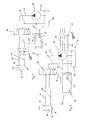
- Fig. 1 is a cutting device with a rotatably driven by a drive device 3 blade carrier 2 to recognize the endless strand 1, in this case a double strand, a product of the tobacco industry, such as a form-fixed by a wrapping strip tobacco rod or filter strand is supplied.
- the knife carrier 2 is formed by a drum and has two radially outwardly projecting blades 5 and 6, which cut during the rotation of the blade carrier 2 through the strand 1 and thereby separate the products of the strand 1 in a predetermined length.
- the knife carrier 2 is angularly adjustable for a format change via an adjusting device 4 about a perpendicular to the strand 1 extending axis I, wherein the knife carrier 2 with a base plate 7, the drive means 3 and a part of the adjusting device 4 relative to a base 8 is rotated.
- the adjusting device 4 is supported stationarily on the base 8 or another stationary part, and may be formed, for example, by a servomotor or a hydraulic adjusting cylinder.
- blocking device 9 which determines the base plate 7 and the blade carrier 2 in the locked position relative to the base and must be unlocked for an adjustment of the blade carrier 2.
- the blocking device 9 comprises a piston-cylinder unit with a guided in a cylinder 31 piston 10 which limits two pressure chambers 14 and 15 in the cylinder 31.
- the piston 10 is provided with a piston rod 11, which is led out of the cylinder 31 and at its end a locking pin 12 has.
- the blocking bolt 12 passes through a passage opening 35 in the base 8 and protrudes with its end in the locking position into a recess 13 of the base plate 7, so that the blocking bolt 12 connects the base plate 7 in the locking position positively in the direction of rotation with the base 8.
- the blocking bolt 12 and / or the recess 13 of the base plate 7 and / or the passage opening 35 of the base 8 on a self-locking blocking design, not shown, which prevents the locking bolt 12 automatically moves out of this position after locking or unlocking.
- the blocking device 9 remains after the locking or unlocking without further pressurization in the respective position, which is particularly important for the Verrieglungs ein, since the blocking device 9 in principle during operation of the cutting device, ie during the vast period of time, in the locked position located.
- a T-shaped clamping head 36 is provided on the piston rod 11.
- the blocking device 9 is unlocked, so that the knife carrier 2 with the base plate 7 relative to the base 8 can be rotated.
- the piston 10 is moved downward by a pressurization of the pressure chamber 15, whereby the clamping head 36 braces the base plate 7 by exerting a clamping force against the base 7.
- the blocking device 9 described fixes the base plate 7 in a force-fitting manner relative to the base 8. This clamping of the base plate 7 is referred to as locking, it is only important that the base plate 7 is then fixed against rotation relative to the base.
- an energy source 30 is provided, which is formed by a pressure medium reservoir 28 and a pressure medium pump 19.
- the pressure medium pump 19 is arranged in a pressure medium line 21 and promotes the pressure medium in an activation from the pressure medium reservoir 28 to a switching device 18, which is realized here by a switchable multi-way valve. Between the multi-way valve and the pressure medium reservoir 28, a second pressure medium line 20 is also provided, via which the pressure medium can flow back into the pressure medium reservoir 28.
- the multi-way valve has three different switching positions, wherein in the pressure medium line 21 supplied pressure medium is forwarded in a first switching position in a pressure medium line 16 for unlocking the blocking device 9 and in a second switching position in a pressure medium line 17 for locking the blocking device 9.
- the pressure medium is not forwarded, and the connection between the pressure medium lines 20 and 21 on one side of the switching device 18 and the pressure medium lines 16 and 17 on the other side of the switching device 18 is interrupted.
- the third switching position can also be referred to as a neutral position and is the switching position, in which the switching device is moved back after the execution of the locking or unlocking.
- the pressure medium is then introduced into one of the pressure medium lines 16 or 17 and into one of the pressure chambers 14 or 15 and the piston 10 is displaced in one direction until the locking pin 12, for example, no longer engages in the recess 13 for unlocking and the base plate 7 thereby pivoted relative to the base 8 can be.
- the reverse direction of movement of the locking pin 12 is retracted into the recess 13 until the base plate 7 is locked against rotation relative to the base 8.
- a control unit 23 is provided with an input device 32, which is connected via control lines 24 and 25 to the switching device 18 and to the pressure medium pump 19.
- a switch 22 formed by a key switch, required to connect the pressure medium pump 19 to the power supply.
- the switch 22 is connected via a signal line 26 to the control unit 23, which comprises an input device 32 in the form of a touch-sensitive screen in a structural unit.
- the control unit 23 which comprises an input device 32 in the form of a touch-sensitive screen in a structural unit.
- an actuating surface 33 is shown, which, for example, a prompt "unlocking device?" may include.
- the question is answered in the affirmative, whereby a corresponding control signal is forwarded to the switch 22.
- the switch 22 must be actuated by inserting and turning the key until the pressure medium pump 19 delivers the pressure medium as intended from the pressure medium reservoir 28.
- the actuation of the switch 22 triggers the energy flow, which is finally used to unlock or lock the blocking device 9.
- a new operation surface with a prompt "locking lock?".
- the switching device 18 is then moved to the second switching position.
- a second actuating surface appears 33 with a command prompt, such as "execute locking process?", Whereupon the switch 22 is actuated and the pressure medium pump 19 is activated.
- the program sequence is interrupted repeatedly, so that 9 repeated manual actions are required for the complete unlocking or locking of the blocking device, so that the movement process can not inadvertently be triggered and executed in any case.
- the switch 22 is not present and instead a switch 27, in this case also a key switch, provided with a pressure medium lines 16 and 17 occlusive valve is actuated.
- the valve is also connected via a signal line 34 to the control unit 23, and is operated in the same manner after a command prompt as the switch 22 in the embodiment of Fig. 3 in that a signal for opening the pressure medium lines 16 and 17 is passed to the valve and the opening process is triggered by the actuation of the switch 27.
- both pressure medium lines 16 and 17 are opened at the same time, so that the pressure medium for locking and unlocking of the blocking device 9 flows in one of the pressure medium lines 16 and 17 and flows out of the respective other pressure medium line 16 or 17. Since this is a pressure medium circuit, but it would also be conceivable to close only one of the pressure medium lines 16 or 17 with the valve and to open the same when actuated.
- the unlocking of the blocking device 9 is carried out as follows. First, after invoking a program menu, the operator is prompted to make an entry as to whether the blocking device 9 is to be unlocked, this input can implicitly already be included in the menu call. The switching device 18 is then moved to a first position in which the pressure medium line 21 is connected to the pressure medium line 16. As far as the sequence of the various embodiments of the Fig. 3 and the Fig. 4 identical.
- Fig. 3 would then display another prompt in the form of an on-screen touch-sensitive actuating surface 33 on the screen, via which the operator is requested to continue the locking or unlocking operation to actuate the actuating surface 33. If the operator confirms this prompt by touching the actuating surface 33, the pressure medium pump 19 is activated after the key switch 22 is actuated and the blocking device 9 is unlocked by pressurizing the pressure chamber 15 and displacing the piston 10 with the blocking bolt 12 out of the recess 13.
- the pressure medium pump 19 is activated simultaneously or following the operation of the switching device 18, in which case no manual input is required.
- the pressure medium flow or the pressure medium under pressure is already promoted at the time of displacement of the switching device 18 in the first switching position or shortly thereafter. Since the valve is still closed in the pressure medium line 16 at this time, the switch 22 must be operated manually via the key to unlock the blocking device 9, so that the pressure fluid under pressure through the open pressure medium line 16 further into the pressure chamber 15 of the cylinder 31 can flow.
- the actuation of the switch 22 triggers the energy flow, which is formed by the further flow of the pressurized pressure medium.
- the same procedure results for the locking of the blocking device 9 with the difference that the switching device 18 is in this case in a second switching position in which the pressure medium line 21 is connected to the pressure medium line 17.
- the advantage of the invention can be seen in the fact that the locking and unlocking process is supported by the external power source 30 and thereby can be performed much faster and more accurate. Furthermore, the beginning of the unlocking and locking operation requires the manual actuation of the switching device 18 and of the switch 22 or 27, so that the risk of an unwanted or erroneous triggering of the movement process can be excluded. Another advantage is that the operator is deliberately asked for explicit confirmation of locking or unlocking on the actuating surface 33, so that the handling is practically self-explanatory and can be performed by an untrained person without difficulty and without prior knowledge.
- the switch 22 or the switch 27 may still be secured by an additional securing part against unauthorized or unintentional actuation, which must be moved manually before actuation of the switch 22 or 27 from a securing position to an unlocked position.
- This may for example be a cover with an additional lock, which must be removed before the operation of the switch 22 or 27.
- Another advantage of the invention is the fact that the triggering of the locking and unlocking although done manually, so is subject to some human control, the locking and unlocking itself but controlled and supported by the power source 30 is supported so that they considerably can be done more accurately and faster.
Landscapes
- Fluid-Pressure Circuits (AREA)
- Manufacturing Of Cigar And Cigarette Tobacco (AREA)
Abstract
Description
- Schneideinrichtung zum Trennen von Produkten der Tabak verarbeitenden Industrie von einem endlosen zugeführten Strang
- Die Erfindung betrifft eine Schneideinrichtung zum Trennen von Produkten der Tabak verarbeitenden Industrie von einem endlosen zugeführten Strang mit den Merkmalen des Oberbegriffs von Anspruch 1.
- Eine solche Schneideinrichtung ist z.B. aus der
GB 2 089 187 A - Damit muss der Winkel des Messerträgers zu dem Strang bei einem Formatwechsel an die geänderte Stranggeschwindigkeit angepasst werden, damit die Schnittfläche der Produkte senkrecht zu deren Längsachse ausgerichtet ist.
- In der aus der
GB 2 089 187 A - Insgesamt ist der rein mechanisch ausgelegte Klemmmechanismus unbefriedigend. Im modernen Maschinenbau, insbesondere im Werkzeugmaschinenbau, werden hydraulisch wirkende Spannelemente zum Festsetzen verschiedener Baugruppen zueinander eingesetzt, da dadurch größere Kräfte aufgebracht werden können und der Klemmvorgang selbstgesteuert erfolgen kann. Bei der vorliegenden Schneideinrichtung muss der Messerträger festgelegt werden, welcher eine Masse von bis zu 40 kg aufweist und zu einer Drehbewegung von bis zu 3000 U/min angetrieben wird. Es sind also sehr hohe Klemmkräfte zur Festlegung des Messerträgers erforderlich, damit sich dieser während des Betriebes nicht selbsttätig wieder verstellt. Des Weiteren ist eine sehr hohe Positioniergenauigkeit des Messerträgers in der geklemmten Lage erforderlich, weil die Bewegung der an dem Messerträger angeordneten Messer während der Schnittbewegung die Bewegung des Stranges mit ausführen müssen und dabei durch einen Schlitz eines tubenförmigen Gegenlagers geführt werden müssen, welches den Strang während der Schnittbewegung unterstützt. Der Messerträger mit den radial abragenden Messern und die Gegenlager stellen dabei kollisionsgefährdete Baugruppen dar, so dass diese äußerst präzise aufeinander abgestimmt werden müssen und die voreingestellte Position auf keinen Fall verändert werden darf. Dies ist besonders wichtig, wenn Messerträger und Gegenlager über separate Einzelantriebe angetrieben werden und nicht über ein Getriebe mechanisch miteinander gekoppelt sind. Daher muss in jedem Fall sichergestellt sein, dass der hydraulische Klemmmechanismus dauerhaft funktioniert und ausgeschlossen werden kann, dass der hydraulische Klemmmechanismus durch einen Programmfehler, einen Bedienfehler und/oder während des Dauerbetriebes der Schneideinrichtung unbeabsichtigt betätigt wird oder seine Klemmkraft verliert. Dies ist insbesondere deshalb wichtig, da die Anforderungen hinsichtlich Klemmkraft und Genauigkeit wesentlich höher sind als bei Werkzeugmaschinen.
- Aufgabe der Erfindung ist es, eine Schneideinrichtung mit einem drehbar antreibbaren Messerträgerkopf zu schaffen, bei der die Gefahr einer unbeabsichtigten Verstellung des Winkels ausgeschlossen ist. Ferner soll der Winkel des Messerträgers zu dem Strang bei einem Formatwechsel (also während des Stillstandes der Maschine) in einer kürzeren Zeit verstellbar sein.
- Die Aufgabe wird erfindungsgemäß durch eine Schneideinrichtung mit den Merkmalen des Anspruchs 1 gelöst. Weitere bevorzugte Ausführungsformen der Erfindung sind den Unteransprüchen, den Figuren und der zugehörigen Beschreibung zu entnehmen.
- Zur Lösung der Aufgabe wird erfindungsgemäß vorgeschlagen, dass eine manuell betätigbare Schalteinrichtung zum Verbinden der Blockiereinrichtung mit einer externen Energiequelle vorgesehen ist, welche mehrere Schaltstellungen aufweist, wobei die Blockiereinrichtung in einer ersten Schaltstellung der Schalteinrichtung durch eine Verbindung mit der externen Energiequelle entriegelbar, in einer zweiten Schaltstellung durch eine Verbindung mit der externen Energiequelle verriegelbar ist, wobei zwischen der Energiequelle und der Blockiereinrichtung zusätzlich ein manuell betätigbarer, den Energiefluss auslösender Schalter vorgesehen ist.
- Die vorgeschlagene Lösung weist den Vorteil auf, dass der Entund Verriegelungsvorgang der Blockiereinrichtung durch eine externe Energiequelle unterstützt wird und dadurch bereits erheblich vereinfacht und in einer kürzeren Zeitspanne durchführbar ist. Ferner können durch die Verwendung der vorgeschlagenen Schalteinrichtung beide Bewegungsvorgänge unter Verwendung einer einzigen Energiequelle bewirkt werden. Außerdem wird der Bewegungsvorgang erst durch eine manuelle Betätigung der Schalteinrichtung und des Schalters ermöglicht, so dass eine bewusste manuelle Handlung in zwei aufeinanderfolgenden Schritten, nämlich der Betätigung der Schalteinrichtung und der Betätigung des Schalters in einer vorbestimmten Reihenfolge erforderlich ist, damit der Entriegelungsvorgang und der Verriegelungsvorgang der Blockiereinrichtung ausgelöst und vollzogen wird. Damit kann die Wahrscheinlichkeit einer ungewollten Ent- oder Verriegelung der Blockiereinrichtung, z.B. durch eine versehentliche Betätigung der Blockiereinrichtung oder durch einen Fehler in einem Programmablauf, ausgeschlossen werden. Als externe Energiequelle soll jede Energiequelle verstanden werden, welche durch die manuelle Betätigung des Schalters eine die Bewegung der Blockiereinrichtung unterstützende Kraft erzeugt, unabhängig von der Anordnung und der Art der Energiequelle. Der Vorteil der Erfindung ist in der Kombination der die Bewegung unterstützenden externen Energiequelle mit der bewusst manuell zu betätigenden Schalteinrichtung und dem zu betätigenden Schalter zu sehen. Außerdem kann der Bewegungsvorgang z.B. durch eine Steuerung des Energieflusses erheblich genauer vollzogen werden. Die erforderliche manuelle Betätigung der Schalteinrichtung und des Schalters stellen bewusst vorzunehmende manuelle Handlungen dar, welche zwingend erforderlich sind, so dass eine unkontrollierte und ungewollte Ent- und Verriegelung der Blockiereinrichtung ausgeschlossen werden kann.
- Weiter wird vorgeschlagen, dass die Blockiereinrichtung in einer dritten Schaltstellung von der externen Energiequelle getrennt ist. Durch das Vorsehen der dritten Schaltstellung und der dadurch bewirkten Trennung der Blockiereinrichtung von der externen Energiequelle kann verhindert werden, dass die Blockiereinrichtung z.B. durch einen Defekt des manuell zum Auslösen des Energieflusses vorgesehenen Schalters oder durch einen Programmfehler unbeabsichtigt mit der Energiequelle verbunden und ungewollt ent- oder verriegelt wird.
- Weiter wird vorgeschlagen, dass die externe Energiequelle durch ein Druckmittelreservoir und eine Druckmittelpumpe gebildet ist. Die Druckmittelpumpe dient dazu, ein Druckmittel aus dem Druckmittelreservoir in einen Druckmittelkreislauf zu fördern, welches zur Ent- und Verriegelung der Blockiereinrichtung auf einfache Art und Weise genutzt werden kann. Sofern die Blockiereinrichtung einen beidseitig mit dem Druckmittel beaufschlagbaren, in einem Zylinder geführten Kolben umfasst, kann das Druckmittel ferner auf einfache Art und Weise sowohl zur Ver- als auch zur Entriegelung genutzt werden.
- In diesem Fall wird weiter vorgeschlagen, dass die Schalteinrichtung durch ein in dem Druckmittelkreislauf angeordnetes Mehrwegeventil gebildet ist. Durch das Mehrwegeventil kann das Druckmittel in Abhängigkeit von der Stellung des Mehrwegeventils wahlweise in einen der Drückraume geleitet werden, der durch jeweils eine der Seiten des Kolbens begrenzt ist, so dass der Kolben unter Verwendung eines einzigen Druckmittelreservoirs in beide Richtungen bewegbar und die Blockiereinrichtung infolgedessen sowohl ent- als auch verriegelt werden kann.
- Weiter wird vorgeschlagen, dass der den Energiefluss auslösende Schalter ein Betätigungsschalter der Druckmittelpumpe ist. Da die Druckmittelpumpe das eigentliche den Energiefluss, in diesem Fall der Druckmittelstrom, aufbauende Bauteil ist, kann durch die Betätigung der Druckmittelpumpe der Energiefluss unmittelbar ausgelöst und bei einer anschließenden Deaktivierung der Druckmittelpumpe entsprechend auf Null zurückgesetzt werden, so dass der Ent- und Verriegelungsvorgang unmittelbar ausgelöst und beendet werden kann.
- Alternativ wird vorgeschlagen, dass der den Energiefluss auslösende Schalter durch ein in dem Druckmittelkreislauf zwischen dem Mehrwegeventil und der Blockiereinrichtung angeordnetes, manuell betätigbares Ventil gebildet ist. Das Ventil ist dabei bevorzugt so ausgebildet, dass bei geöffnetem Ventil ein Zulauf des Druckmittel in einen der Druckräume möglich ist, während das Druckmittel aus dem anderen Druckraum zurück in das Druckmittelreservoir strömen kann. Nach der Ent- oder Verriegelung der Blockiereinrichtung wird das Ventil wieder geschlossen, so dass das Druckmittel nicht mehr auf die Blockiereinrichtung wirkt. Der Energiefluss wird in diesem Fall dadurch ausgelöst, indem das durch die vorangegangene Betätigung der Druckmittelpumpe bereits unter Druck stehende Druckmittel durch eine Öffnung des Ventils freigegeben wird und in einen der Druckräume weitergeleitet wird. Da es sich hier um einen Druckmittelkreislauf handelt, wäre es auch denkbar, nur eine der Druckmittelleitungen mit dem Ventil zu verschließen oder zu öffnen.
- Weiter wird vorgeschlagen, dass der den Energiefluss auslösende Schalter ein Schlüsselschalter ist. Der Vorteil dieser Lösung ist darin zu sehen, dass der Schalter nur unter Verwendung eines Schlüssels betätigbar ist, durch den einerseits der Personenkreis, welcher den Schalter betätigen kann, beschränkt ist und andererseits die Betätigung des Schalters eine nochmalige manuelle Handlung, nämlich das Einführen und Umdrehen des Schlüssels erfordert, so dass die Wahrscheinlichkeit einer ungewollten oder unbefugten Betätigung des Schalters weiter verringert werden kann.
- Die Wahrscheinlichkeit einer unbeabsichtigten oder unbefugten Betätigung kann ferner weiter verringert werden, indem der den Energiefluss auslösende Schalter durch ein zusätzliches mechanisches Sicherungsteil gesichert ist, welches den Schalter in einer Sicherungsstellung gegen eine unbeabsichtigte Betätigung sichert und vor einer Betätigung des Schalters manuell aus der Sicherungsstellung in eine entsicherte Stellung bewegt werden muss. Das Sicherungsteil kann z.B. eine Abdeckung des Schalters oder auch ein Blockierteil sein, welches vor der Betätigung des Schalters entfernt oder gelöst werden muss. Ferner kann das Sicherungsteil auch ein einfaches Schloss sein, welches den Zugang zu dem Schalter in der geschlossenen Stellung verhindert und nur durch einen Schlüssel zu öffnen ist.
- In einer weiteren bevorzugten Ausführungsform der Erfindung wird vorgeschlagen, dass eine Steuereinheit zur Steuerung der Entriegelungs- und Verrieglungsbewegung der Blockiereinrichtung nach der manuellen Betätigung der Schalteinrichtung und nach der Betätigung des den Energiefluss auslösenden Schalters vorgesehen ist. Der Entriegelungsvorgang und der Verrieglungsvorgang kann damit jeweils in zwei Schritte unterteilt werden, nämlich in einem ersten Schritt dem manuellen Auslösen der Bewegung durch die Betätigung der Schalteinrichtung und des Schalters und in einem zweiten Schritt dem darauffolgenden gesteuerten Bewegungsablauf der Blockiereinrichtung. Insbesondere kann die Steuereinheit z.B. die externe Energiequelle steuern, so dass diese nach dem Erreichen der Ver- oder Entriegelungsstellung der Blockiereinrichtung selbsttätig abgeschaltet wird.
- Ferner kann eine Eingabeeinrichtung vorgesehen sein, welche eine Betätigungsfläche zur Betätigung der Schalteinrichtung und eine Betätigungsfläche für den den Energiefluss auslösenden Schalter aufweist. Damit können die Schalteinrichtung und der Schalter bedienerfreundlich an ein und derselben Eingabeeinrichtung manuell betätigt werden. Eine solche Betätigungsfläche kann z.B. eine berührungssensitive Betätigungsfläche auf einem entsprechenden Bildschirm sein, wobei die Betätigungsflächen zur Betätigung der Schalteinrichtung und zur Betätigung des Schalters nacheinander auf dem Bildschirm erscheinen und dem Operator dadurch gleichzeitig die Reihenfolge der Betätigung vorgeben. Die Betätigung der Schalteinrichtung und des Schalters kann dabei auch Teil eines Ablaufs von aufeinanderfolgenden Eingabeaufforderungen eines Programmablaufs sein, welcher durch die Eingabeaufforderung jeweils unterbrochen wird.
- Dabei können die Eingabeeinrichtung und die Steuereinheit in einer weiteren bevorzugten Ausführungsform der Erfindung eine Einheit bilden. Die durch die Betätigung der Schalteinrichtung und des Schalters in der Eingabeeinrichtung erzeugten Signale können dadurch besonders einfach der Steuereinheit zugeführt und weiterverarbeitet werden. Die vorgeschlagene Lösung ist ferner besonders sinnvoll, wenn die Eingabeeinrichtung ein berührungssensitiver Bildschirm ist, der gleichzeitig auch zu einer Betätigung der Steuereinheit bzw. zur Anzeige von Daten der Steuereinheit genutzt werden kann.
- Weiter wird vorgeschlagen, dass die Blockiereinrichtung selbsthemmend ausgebildet ist. Die Blockiereinrichtung bleibt dadurch nach der Ent- oder Verrieglung in der jeweiligen entriegelten oder verriegelten Endstellung stehen, ohne dass dazu eine andauernde Beaufschlagung der Blockiereinrichtung durch die externe Energiequelle erforderlich ist. Die Blockiereinrichtung wird dann erst durch eine darauffolgende Aufhebung der Selbsthemmung durch eine erneute Betätigung der Schalteinrichtung in die jeweils andere Stellung zur Ent- oder Verrieglung der Blockiereinrichtung und eine Betätigung des Schalters gelöst, so dass eine ungewollte und insbesondere selbsttätige Bewegung der Blockiereinrichtung aus der verriegelten oder entriegelten Stellung verhindert werden kann.
- Weiter wird vorgeschlagen, dass die Blockiereinrichtung einen die Basis durchgreifenden Klemmkopf umfasst, welcher den Messerträger oder ein drehfest mit dem Messerträger verbundenes Teil in der Verriegelungsstellung durch Ausübung einer Klemmkraft gegenüber der Basis drehfest verspannt. Der Messerträger wird dadurch kraftschlüssig gegenüber der Basis verspannt, was den Vorteil aufweist, dass die Verriegelung über eine reine Klemmkraft auch eine stufenlose Verstellung des Messerträgers auf einfache Art und Weise ermöglicht.
- Die Erfindung wird im Folgenden anhand bevorzugter Ausführungsformen unter Bezugnahme auf die beigefügten Figuren erläutert. Dabei zeigt:
-
Fig. 1 eine Schneideinrichtung mit einem zugeführten endlosen Doppelstrang, -
Fig. 2 eine formschlüssig wirkende Blockiereinrichtung in Einzeldarstellung, -
Fig. 3 einen Druckmittelkreislauf mit einer über einen Schlüsselschalter betätigbaren Druckmittelpumpe, -
Fig. 4 einen Druckmittelkreislauf mit einem zwischen der Blockiereinrichtung und der Schalteinrichtung angeordneten Ventil, und -
Fig. 5 eine kraftschlüssig wirkende Blockiereinrichtung in Einzeldarstellung. - In der
Fig. 1 ist eine Schneideinrichtung mit einem von einer Antriebseinrichtung 3 drehbar antreibbaren Messerträger 2 zu erkennen, der ein endloser Strang 1, in diesem Fall ein Doppelstrang, eines Produktes der Tabak verarbeitenden Industrie, wie z.B. ein durch einen Umhüllungsstreifen formfixierter Tabakstrang oder Filterstrang, zugeführt wird. Der Messerträger 2 ist durch eine Trommel gebildet und weist zwei radial nach außen vorstehende Messer 5 und 6 auf, welche während der Drehbewegung des Messerträgers 2 durch den Strang 1 schneiden und dadurch die Produkte in einer vorbestimmten Länge von dem Strang 1 trennen. Der Messerträger 2 ist für einen Formatwechsel über eine Verstelleinrichtung 4 um eine senkrecht zu dem Strang 1 verlaufende Achse I winklig verstellbar, wobei der Messerträger 2 mit einer Grundplatte 7, der Antriebseinrichtung 3 und einem Teil der Verstelleinrichtung 4 gegenüber einer Basis 8 verdreht wird. Die Verstelleinrichtung 4 stützt sich dazu ortsfest an der Basis 8 oder einem anderen feststehenden Teil ab, und kann z.B. durch einen Servomotor oder einen hydraulischen Verstellzylinder gebildet sein. - Zwischen der Grundplatte 7 und der Basis 8 ist eine in der
Fig. 2 zu erkennende Blockiereinrichtung 9 vorgesehen, welche die Grundplatte 7 und den Messerträger 2 in der verriegelten Stellung gegenüber der Basis festlegt und für eine Verstellung des Messerträgers 2 entriegelt werden muss. Die Blockiereinrichtung 9 umfasst eine Kolbenzylindereinheit mit einem in einem Zylinder 31 geführten Kolben 10, der zwei Druckräume 14 und 15 in dem Zylinder 31 begrenzt. Der Kolben 10 ist mit einer Kolbenstange 11 versehen, welche aus dem Zylinder 31 herausgeführt ist und an ihrem Ende einen Blockierbolzen 12 aufweist. Der Blockierbolzen 12 durchgreift eine Durchgangsöffnung 35 in der Basis 8 und ragt mit seinem Ende in der Verriegelungsstellung in eine Ausnehmung 13 der Grundplatte 7, so dass der Blockierbolzen 12 die Grundplatte 7 in der Verriegelungsstellung formschlüssig in Verdrehrichtung mit der Basis 8 verbindet. Des Weiteren weist der Blockierbolzen 12 und/oder die Ausnehmung 13 der Grundplatte 7 und/oder die Durchgangsöffnung 35 der Basis 8 eine nicht dargestellte selbsthemmende Blockiergestaltung auf, welche verhindert, dass sich der Blockierbolzen 12 nach der Ver- oder Entriegelung selbsttätig wieder aus dieser Stellung herausbewegt. Dadurch bleibt die Blockiereinrichtung 9 nach der Verriegelung oder Entriegelung auch ohne eine weitere Druckbeaufschlagung in der jeweiligen Stellung stehen, was insbesondere für die Verrieglungsstellung wichtig ist, da sich die Blockiereinrichtung 9 grundsätzlich während des Betriebes der Schneideinrichtung, also während der überwiegenden Zeitdauer, in der Verriegelungsstellung befindet. - In der
Fig. 5 ist eine alternative Ausführungsform der Blockiereinrichtung 9 zu erkennen, bei der an der Kolbenstange 11 statt des Blockierbolzens 12 ein T-förmiger Klemmkopf 36 vorgesehen ist. In der dargestellten Stellung ist die Blockiereinrichtung 9 entriegelt, so dass der Messerträger 2 mit der Grundplatte 7 gegenüber der Basis 8 verdreht werden kann. Zum Verriegeln der Blockiereinrichtung 9 wird der Kolben 10 durch eine Druckbeaufschlagung des Druckraumes 15 nach unten bewegt, wodurch der Klemmkopf 36 die Grundplatte 7 durch Ausübung einer Klemmkraft gegenüber der Basis 7 verspannt. Die beschriebene Blockiereinrichtung 9 legt die Grundplatte 7 damit kraftschlüssig gegenüber der Basis 8 fest. Dieses Festklemmen der Grundplatte 7 wird hier als Verriegeln bezeichnet, wichtig ist nur, dass die Grundplatte 7 anschließend drehfest gegenüber der Basis festgelegt ist. - In der
Fig. 3 und derFig. 4 ist der Druckmittelkreislauf von zwei alternativen Ausführungsformen der erfindungsgemäß vorgeschlagenen Ver- und Entriegelung der Blockiereinrichtung 9 dargestellt, wobei identische Bauteile mit identischen Bezugszeichen versehen sind. - Bei beiden Ausführungsformen ist eine Energiequelle 30 vorgesehen, welche durch ein Druckmittelreservoir 28 und eine Druckmittelpumpe 19 gebildet ist. Die Druckmittelpumpe 19 ist in einer Druckmittelleitung 21 angeordnet und fördert das Druckmittel bei einer Aktivierung aus dem Druckmittelreservoir 28 zu einer Schalteinrichtung 18, welche hier durch ein schaltbares Mehrwegeventil verwirklicht ist. Zwischen dem Mehrwegeventil und dem Druckmittelreservoir 28 ist ferner eine zweite Druckmittelleitung 20 vorgesehen, über die das Druckmittel in das Druckmittelreservoir 28 zurückströmen kann.
- Das Mehrwegeventil weist drei verschiedene Schaltstellungen auf, wobei das in der Druckmittelleitung 21 zugeführte Druckmittel in einer ersten Schaltstellung in eine Druckmittelleitung 16 zur Entriegelung der Blockiereinrichtung 9 und in einer zweiten Schaltstellung in eine Druckmittelleitung 17 zur Verrieglung der Blockiereinrichtung 9 weitergeleitet wird. In der dritten Schaltstellung der Schalteinrichtung 18 wird das Druckmittel nicht weitergeleitet, und die Verbindung zwischen den Druckmittelleitungen 20 und 21 auf einer Seite der Schalteinrichtung 18 und den Druckmittelleitungen 16 und 17 auf der anderen Seite der Schalteinrichtung 18 unterbrochen. Die dritte Schaltstellung kann auch als Neutralstellung bezeichnet werden und ist die Schaltstellung, in welche die Schalteinrichtung nach dem Ausführen der Verriegelung oder der Entriegelung wieder zurückbewegt wird.
- Je nach der Stellung der Schalteinrichtung 18 wird das Druckmittel dann in eine der Druckmittelleitungen 16 oder 17 und in einen der Druckräume 14 oder 15 eingeleitet und der Kolben 10 in eine Richtung verschoben, bis der Blockierbolzen 12 z.B. zur Entriegelung nicht mehr in die Ausnehmung 13 eingreift und die Grundplatte 7 dadurch gegenüber der Basis 8 verschwenkt werden kann. In der umgekehrten Bewegungsrichtung wird der Blockierbolzen 12 in die Ausnehmung 13 eingefahren, bis die Grundplatte 7 gegenüber der Basis 8 drehfest verriegelt ist.
- Ferner ist bei beiden Ausführungsformen eine Steuereinheit 23 mit einer Eingabeeinrichtung 32 vorgesehen, welche über Steuerleitungen 24 und 25 mit der Schalteinrichtung 18 und mit der Druckmittelpumpe 19 verbunden ist.
- In der Ausführungsform in der
Fig. 3 ist zur Betätigung der Druckmittelpumpe 19 die vorherige Betätigung eines Schalters 22, gebildet durch einen Schlüsselschalter, erforderlich, um die Druckmittelpumpe 19 an die Stromzufuhr anzuschließen. Der Schalter 22 ist über eine Signalleitung 26 mit der Steuereinheit 23 verbunden, welche eine Eingabeeinrichtung 32 in Form eines berührungssensitiven Bildschirms in baulicher Einheit umfasst. Auf dem Bildschirm ist beispielhaft eine Betätigungsfläche 33 dargestellt, welche z.B. eine Eingabeaufforderung "Blockiereinrichtung entriegeln?" beinhalten kann. Durch Berühren der Betätigungsfläche 33 wird die Frage mit Ja beantwortet, wodurch ein entsprechendes Ansteuersignal an den Schalter 22 weitergeleitet wird. Daraufhin muss der Schalter 22 durch Einstecken und Drehen des Schlüssels erst betätigt werden, bevor die Druckmittelpumpe 19 das Druckmittel bestimmungsgemäß aus dem Druckmittelreservoir 28 fördert. Damit löst die Betätigung des Schalters 22 den Energiefluss aus, der schließlich zur Ent- oder Verriegelung der Blockiereinrichtung 9 genutzt wird. Nachdem der Verstellvorgang des Messerträgers 2 beendet ist, erscheint auf dem Bildschirm eine neue Betätigungsfläche mit einer Eingabeaufforderung "Blockiereinrichtung verriegeln?". Bei einer Betätigung der Betätigungsfläche wird die Schalteinrichtung 18 daraufhin in die zweite Schaltstellung bewegt. Anschließend erscheint eine zweite Betätigungsfläche 33 mit einer Eingabeaufforderung, wie z.B. "Verriegelungsvorgang ausführen?", woraufhin der Schalter 22 betätigt wird und die Druckmittelpumpe 19 aktiviert wird. - Der Programmablauf wird demnach wiederholt unterbrochen, so dass zur vollständigen Ent- oder Verriegelung der Blockiereinrichtung 9 wiederholte manuelle Handlungen erforderlich sind, so dass der Bewegungsvorgang in jedem Fall nicht unbeabsichtigt ausgelöst und vollzogen werden kann.
- In dem Ausführungsbeispiel in der
Fig. 4 ist der Schalter 22 nicht vorhanden und stattdessen ein Schalter 27, in diesem Fall ebenfalls ein Schlüsselschalter, vorgesehen, mit dem ein die Druckmittelleitungen 16 und 17 verschließendes Ventil betätigbar ist. Das Ventil ist ebenfalls über eine Signalleitung 34 mit der Steuereinheit 23 verbunden, und wird in gleicher Weise nach einer Eingabeaufforderung betätigt wie der Schalter 22 in dem Ausführungsbeispiel derFig. 3 , indem ein Signal zur Öffnung der Druckmittelleitungen 16 und 17 an das Ventil geleitet und der Öffnungsvorgang durch die Betätigung des Schalters 27 ausgelöst wird. Bei der Betätigung des Schalters 27 werden grundsätzlich beide Druckmittelleitungen 16 und 17 gleichzeitig geöffnet, so dass das Druckmittel zur Ver- und Entriegelung der Blockiereinrichtung 9 in einer der Druckmittelleitungen 16 und 17 zuströmt und aus der jeweils anderen Druckmittelleitung 16 oder 17 abströmt. Da es sich hier um einen Druckmittelkreislauf handelt, wäre es aber auch denkbar, nur eine der Druckmittelleitungen 16 oder 17 mit dem Ventil zu verschließen und bei einer Betätigung desselben zu öffnen. - Die Entriegelung der Blockiereinrichtung 9 wird wie folgt vorgenommen. Zuerst wird der Operator nach dem Aufruf eines Programmmenüs aufgefordert eine Eingabe zu tätigen, ob die Blockiereinrichtung 9 entriegelt werden soll, wobei diese Eingabe implizit auch schon in dem Menüaufruf enthalten sein kann. Die Schalteinrichtung 18 wird daraufhin in eine erste Stellung bewegt, in der die Druckmittelleitung 21 mit der Druckmittelleitung 16 verbunden ist. Soweit ist der Ablauf der verschiedenen Ausführungsbeispiele der
Fig. 3 und derFig. 4 identisch. - In der
Fig. 3 würde dann eine weitere Eingabeaufforderung in Form einer auf dem Bildschirm erscheinenden berührungssensitiven Betätigungsfläche 33 auf den Bildschirm angezeigt, über die der Operator für eine Fortführung des Ver- oder Entriegelungsvorganges zu einer Betätigung der Betätigungsfläche 33 aufgefordert wird. Bestätigt der Operator diese Eingabeaufforderung durch Berühren der Betätigungsfläche 33, so wird die Druckmittelpumpe 19 nach dem Betätigen des Schlüsselschalters 22 aktiviert und die Blockiereinrichtung 9 durch eine Druckbeaufschlagung des Druckraumes 15 und eine Verschiebung des Kolbens 10 mit dem Blockierbolzen 12 aus der Ausnehmung 13 heraus entriegelt. - Im Unterschied dazu wird in dem in der
Fig. 4 gezeigten Ausführungsbeispiel die Druckmittelpumpe 19 gleichzeitig oder im Anschluss an die Betätigung der Schalteinrichtung 18 aktiviert, wobei hierzu keine manuelle Eingabe erforderlich ist. Der Druckmittelstrom bzw. das unter Druck stehende Druckmittel wird bereits zum Zeitpunkt der Verschiebung der Schalteinrichtung 18 in die erste Schaltstellung oder kurz darauf im Anschluss gefördert. Da das Ventil in der Druckmittelleitung 16 zu diesem Zeitpunkt noch verschlossen ist, muss zur Entriegelung der Blockiereinrichtung 9 noch der Schalter 22 manuell über den Schlüssel betätigt werden, so dass das unter Druck stehende Druckmittel durch die geöffnete Druckmittelleitung 16 weiter in den Druckraum 15 des Zylinders 31 einströmen kann. - In diesem Fall löst die Betätigung des Schalters 22 den Energiefluss aus, welcher durch das Weiterströmen des unter Druck stehenden Druckmittels gebildet ist. Derselbe Ablauf ergibt sich für die Verrieglung der Blockiereinrichtung 9 mit dem Unterschied, dass die Schalteinrichtung 18 in diesem Fall in einer zweiten Schaltstellung ist, in der die Druckmittelleitung 21 mit der Druckmittelleitung 17 verbunden ist.
- Insgesamt kann der Vorteil der Erfindung darin gesehen werden, dass der Ver- und Entriegelungsvorgang durch die externe Energiequelle 30 unterstützt wird und dadurch wesentlich schneller und genauer vollzogen werden kann. Ferner setzt der Beginn des Ent- und Verriegelungsvorganges die manuelle Betätigung der Schalteinrichtung 18 und des Schalters 22 oder 27 voraus, so dass die Gefahr einer ungewollten oder fehlerhaften Auslösung des Bewegungsvorganges ausgeschlossen werden kann. Ein weiterer Vorteil ist, dass der Operator bewusst zur ausdrücklichen Bestätigung der Ver- oder Entriegelung über die Betätigungsfläche 33 aufgefordert wird, so dass die Handhabung praktisch selbsterklärend ist und auch von einer ungeübten Person ohne Schwierigkeiten und ohne Vorkenntnisse durchgeführt werden kann.
- Ferner kann der Schalter 22 oder der Schalter 27 noch durch ein zusätzliches Sicherungsteil gegen eine unbefugte oder unbeabsichtigte Betätigung gesichert sein, welches vor der Betätigung des Schalters 22 oder 27 manuell aus einer Sicherungsstellung in eine entsicherte Stellung bewegt werden muss. Dies kann z.B. eine Abdeckung mit einem zusätzlichen Schloss sein, welche vor der Betätigung des Schalters 22 oder 27 entfernt werden muss.
- Außerdem ist durch die Verwendung von Schlüsselschaltern zusätzlich eine Art mechanische Sicherung vorgesehen, durch welche die Durchführung der Entriegelung und Verriegelung bzw. die Verstellung des Messerträger 2 auf einen begrenzten Personenkreis eingeschränkt ist, welche im Besitz des Schlüssels sind oder Zugang zu diesem haben.
- Ein weiterer Vorteil der Erfindung ist darin zu sehen, dass die Auslösung des Ver- und Entriegelungsvorganges zwar manuell erfolgt, also einer gewissen menschlichen Kontrolle unterliegt, die Ver- und Entriegelungsbewegung selbst aber gesteuert erfolgt und durch die Energiequelle 30 unterstützt wird, so dass sie erheblich genauer und schneller vollzogen werden kann.
- Als externe Energiequelle 30 wurde hier ein Druckmittelreservoir 28 und eine Druckmittelpumpe 19 beschrieben, es wäre jedoch ohne Nachteile auch denkbar, hier auch einen elektrischen Antrieb vorzusehen, wobei die Schalteinrichtung 18 dann ein schaltbares Getriebe wäre.
Claims (13)
- Schneideinrichtung zum Trennen von Produkten der Tabak verarbeitenden Industrie von einem endlosen zugeführten Strang (1) mit- einem von einer Antriebseinrichtung (3) drehbar antreibbaren Messerträger (2) mit mindestens einem radial abragenden Messer (5,6),- einer feststehenden Basis (8), gegenüber der der Messerträger (2) mittels einer Verstelleinrichtung (4) um eine erste Achse (I) winklig verstellbar ist, und- einer manuell betätigbaren Blockiereinrichtung (9) zur Verriegelung des Messerträgers (2) gegenüber der Basis (8), dadurch gekennzeichnet, dass- eine manuell betätigbare Schalteinrichtung (18) zum Verbinden der Blockiereinrichtung (9) mit einer externen Energiequelle (30) vorgesehen ist, welche mehrere Schaltstellungen aufweist, wobei die Blockiereinrichtung (9)- in einer ersten Schaltstellung der Schalteinrichtung (18) durch eine Verbindung mit der externen Energiequelle (30) entriegelbar und- in einer zweiten Schaltstellung der Schalteinrichtung (18) durch eine Verbindung mit der externen Energiequelle (30) verriegelbar ist, und- zwischen der Energiequelle (30) und der Blockiereinrichtung (9) ein manuell betätigbarer, den Energiefluss auslösender Schalter (22,27) vorgesehen ist.
- Schneideinrichtung nach Anspruch 1, dadurch gekennzeichnet, dass- die Blockiereinrichtung (9) in einer dritten Schaltstellung der Schalteinrichtung (18) von der externen Energiequelle (30) getrennt ist.
- Schneideinrichtung nach Anspruch 1 oder 2, dadurch gekennzeichnet, dass -die externe Energiequelle (30) durch ein Druckmittelreservoir (28) und eine Druckmittelpumpe (19) gebildet ist.
- Schneideinrichtung nach Anspruch 3, dadurch gekennzeichnet, dass -die Schalteinrichtung (18) durch ein in dem Druckmittelkreislauf angeordnetes Mehrwegeventil gebildet ist.
- Schneideinrichtung nach einem der Ansprüche 3 oder 4, dadurch gekennzeichnet, dass -der den Energiefluss auslösende Schalter (22) ein Betätigungsschalter der Druckmittelpumpe (19) ist.
- Schneideinrichtung nach einem der Ansprüche 3 oder 4, dadurch gekennzeichnet, dass -der den Energiefluss auslösende Schalter (27) durch ein in dem Druckmittelkreislauf zwischen dem Mehrwegeventil und der Blockiereinrichtung (9) angeordnetes, manuell betätigbares Ventil gebildet ist.
- Schneideinrichtung nach einem der vorangegangenen Ansprüche, dadurch gekennzeichnet, dass -der den Energiefluss auslösende Schalter (22,27) ein Schlüsselschalter ist.
- Schneideinrichtung nach einem der vorangegangenen Ansprüche, dadurch gekennzeichnet, dass -der den Energiefluss auslösende Schalter (22,27) durch ein zusätzliches mechanisches Sicherungsteil gesichert ist, welches den Schalter (22,27) in einer Sicherungsstellung gegen eine unbeabsichtigte Betätigung sichert und vor einer Betätigung des Schalters (22,27) manuell aus der Sicherungsstellung in eine entsicherte Stellung bewegt werden muss.
- Schneideinrichtung nach einem der vorangegangenen Ansprüche, dadurch gekennzeichnet, dass -eine Steuereinheit (23) zur Steuerung der Entriegelungsund Verrieglungsbewegung der Blockiereinrichtung (9) nach der manuellen Betätigung der Schalteinrichtung (18) und der Betätigung des den Energiefluss auslösenden Schalters (22,27) vorgesehen ist.
- Schneideinrichtung nach einem der vorangegangenen Ansprüche, dadurch gekennzeichnet, dass -eine Eingabeeinrichtung (32) vorgesehen ist, welche eine Betätigungsfläche (33) zur Betätigung der Schalteinrichtung (18) und eine Betätigungsfläche (33) für den den Energiefluss auslösenden Schalter (22,27) aufweist.
- Schneideinrichtung nach Anspruch 9 und 10, dadurch gekennzeichnet, dass -die Eingabeeinrichtung (32) und die Steuereinheit (23) eine Einheit bilden.
- Schneideinrichtung nach einem der vorangegangenen Ansprüche, dadurch gekennzeichnet, dass- die Blockiereinrichtung (9) selbsthemmend ausgebildet ist, und- die Selbsthemmung durch eine durch die in der ersten oder der zweiten Schaltstellung befindliche Schalteinrichtung (18) geschaffene Verbindung zu der externen Energiequelle (30) aufhebbar ist.
- Schneideinrichtung nach einem der vorangegangenen Ansprüche, dadurch gekennzeichnet, dass -die Blockiereinrichtung (9) einen die Basis (8) durchgreifenden Klemmkopf (36) umfasst, welcher den Messerträger (2) oder ein drehfest mit dem Messerträger (2) verbundenes Teil in der Verriegelungsstellung durch Ausübung einer Klemmkraft gegenüber der Basis (8) drehfest verspannt.
Priority Applications (4)
| Application Number | Priority Date | Filing Date | Title |
|---|---|---|---|
| EP12174101.1A EP2679105B1 (de) | 2012-06-28 | 2012-06-28 | Schneideinrichtung zum Trennen von Produkten der Tabak verarbeitenden Industrie von einem endlosen zugeführten Strang |
| ES12174101T ES2531380T3 (es) | 2012-06-28 | 2012-06-28 | Dispositivo de corte para separar productos de la industria tabacalera de una varilla continua alimentada |
| PL12174101T PL2679105T3 (pl) | 2012-06-28 | 2012-06-28 | Urządzenie tnące do odcinania produktów przemysłu tytoniowego od doprowadzonego wałka bez końca |
| CN201310262613.8A CN103504469B (zh) | 2012-06-28 | 2013-06-27 | 从连续的所输送的条上分割烟草加工业的产品的切割装置 |
Applications Claiming Priority (1)
| Application Number | Priority Date | Filing Date | Title |
|---|---|---|---|
| EP12174101.1A EP2679105B1 (de) | 2012-06-28 | 2012-06-28 | Schneideinrichtung zum Trennen von Produkten der Tabak verarbeitenden Industrie von einem endlosen zugeführten Strang |
Publications (3)
| Publication Number | Publication Date |
|---|---|
| EP2679105A1 true EP2679105A1 (de) | 2014-01-01 |
| EP2679105A9 EP2679105A9 (de) | 2014-02-19 |
| EP2679105B1 EP2679105B1 (de) | 2014-12-31 |
Family
ID=46465090
Family Applications (1)
| Application Number | Title | Priority Date | Filing Date |
|---|---|---|---|
| EP12174101.1A Not-in-force EP2679105B1 (de) | 2012-06-28 | 2012-06-28 | Schneideinrichtung zum Trennen von Produkten der Tabak verarbeitenden Industrie von einem endlosen zugeführten Strang |
Country Status (4)
| Country | Link |
|---|---|
| EP (1) | EP2679105B1 (de) |
| CN (1) | CN103504469B (de) |
| ES (1) | ES2531380T3 (de) |
| PL (1) | PL2679105T3 (de) |
Citations (3)
| Publication number | Priority date | Publication date | Assignee | Title |
|---|---|---|---|---|
| GB2089187A (en) | 1980-12-12 | 1982-06-23 | Gd Spa | A device for simultaneously cutting two continuous rods of cigarette |
| US20070272262A1 (en) * | 2003-11-19 | 2007-11-29 | Fiorenzo Draghetti | Cutting Unit for Cutting Continuous Cigarette Rods |
| EP2258220A1 (de) * | 2009-06-06 | 2010-12-08 | Hauni Maschinenbau AG | Schneidvorrichtung der Tabak verarbeitenden Industrie zum Schneiden wenigstens eines geförderten Strangs in eine Vielzahl stabförmiger Artikel sowie Verfahren zum Einrichten und Prüfen der Bebtriebsbereitschaft der Schneidvorrichtung |
Family Cites Families (2)
| Publication number | Priority date | Publication date | Assignee | Title |
|---|---|---|---|---|
| DE10227218A1 (de) * | 2002-06-18 | 2004-01-08 | Focke & Co (Gmbh & Co) | Vorrichtung zum Durchtrennen eines Tabakstrangs |
| ITBO20060056A1 (it) * | 2006-02-02 | 2006-05-04 | Gd Spa | Dispositivo di taglio per articoli da fumo. |
-
2012
- 2012-06-28 ES ES12174101T patent/ES2531380T3/es active Active
- 2012-06-28 PL PL12174101T patent/PL2679105T3/pl unknown
- 2012-06-28 EP EP12174101.1A patent/EP2679105B1/de not_active Not-in-force
-
2013
- 2013-06-27 CN CN201310262613.8A patent/CN103504469B/zh not_active Expired - Fee Related
Patent Citations (3)
| Publication number | Priority date | Publication date | Assignee | Title |
|---|---|---|---|---|
| GB2089187A (en) | 1980-12-12 | 1982-06-23 | Gd Spa | A device for simultaneously cutting two continuous rods of cigarette |
| US20070272262A1 (en) * | 2003-11-19 | 2007-11-29 | Fiorenzo Draghetti | Cutting Unit for Cutting Continuous Cigarette Rods |
| EP2258220A1 (de) * | 2009-06-06 | 2010-12-08 | Hauni Maschinenbau AG | Schneidvorrichtung der Tabak verarbeitenden Industrie zum Schneiden wenigstens eines geförderten Strangs in eine Vielzahl stabförmiger Artikel sowie Verfahren zum Einrichten und Prüfen der Bebtriebsbereitschaft der Schneidvorrichtung |
Also Published As
| Publication number | Publication date |
|---|---|
| CN103504469A (zh) | 2014-01-15 |
| CN103504469B (zh) | 2016-10-12 |
| PL2679105T3 (pl) | 2015-05-29 |
| EP2679105B1 (de) | 2014-12-31 |
| EP2679105A9 (de) | 2014-02-19 |
| ES2531380T3 (es) | 2015-03-13 |
Similar Documents
| Publication | Publication Date | Title |
|---|---|---|
| DE3421452C2 (de) | Vorrichtung zum automatischen Erfassen bzw. Lösen eines Werkzeugträgers bei einem Manipulator | |
| EP0093318B1 (de) | Entschwartungsmaschine | |
| EP2258495B1 (de) | Hydraulischer Feinschneidkopf für eine Presse und Verfahren zu dessen Zustellung | |
| DE2822476A1 (de) | Einrichtung zum schneiden laenglichen profilmaterials, insbesondere von rohrmaterial | |
| EP2694231B1 (de) | TRANSFEREINRICHTUNG FÜR EINE PRESSE ODER PRESSENSTRAßE MIT ACHSANTRIEB UND AUSWECHSELBAREM GRUNDTRÄGER | |
| DE2902684A1 (de) | Vorrichtung zur verwendung bei einem speiser zum abscheren von posten von einer saeule plastischen materials | |
| EP0558872A1 (de) | Verfahren und Vorrichtung zum Aufwickeln von wickelfähigen Substraten | |
| DE3889286T2 (de) | Überwachungseinheit zum Positionieren der Messer in einer Längsschneidvorrichtung. | |
| WO2012145781A1 (de) | Werkzeughalterung für abkantpresse | |
| DE1479547B2 (de) | Vorrichtung zum gleichzeitigen Entfernen überflüssiger· Abfallabschnitte von mehreren fertig geformten Kunststoffteilen, insbesondere von nach dem Blasverfahren hergestellten Hohlkörpern | |
| DE69304614T2 (de) | Stangzufuhrvorrichtung für Stangenschubvorrichtungen an Werkzeugmaschinen | |
| DE202020104847U1 (de) | Kreismesservorrichtung | |
| EP0909230A1 (de) | Werkzeugmaschine zur bearbeitung von werkstückhohlräumen | |
| EP0143257B1 (de) | Werkzeugaufnahme einer Schneidpresse, insbesondere einer Revolverschneidpresse, für den Werkzeugwechsel | |
| DE2628788C2 (de) | Verfahren und Maschine zum lagerichtigen Einspannen eines mit Seitenscheiben versehenen Wickeltragbaumes | |
| EP2679105B1 (de) | Schneideinrichtung zum Trennen von Produkten der Tabak verarbeitenden Industrie von einem endlosen zugeführten Strang | |
| DE2113075C3 (de) | Vorrichtung zur Steuerung eines oder mehrerer Arbeitsvorgänge | |
| EP2676558B1 (de) | Vorrichtung zum Trennen eines endlosen zugeführten Stranges eines Produktes der Tabak verarbeitenden Industrie in einzelne Stäbe | |
| EP3735331B1 (de) | Vorrichtung zum schneiden von blech | |
| EP3511460B1 (de) | Kettenwirkmaschine und verfahren zur bedienerunterstützung bei einer kettenwirkmaschine | |
| EP0699786A2 (de) | Fachbildungsvorrichtung | |
| DE19520718C2 (de) | Blechschere | |
| DE2525896A1 (de) | Verstellbarer anschlag zum aufstellen eines zu bearbeitenden werkstuecks auf einer werkzeugmaschine | |
| DE102007037108B4 (de) | Antriebsanordnung für eine Lebensmittelteilvorrichtung | |
| DE2560465C2 (de) |
Legal Events
| Date | Code | Title | Description |
|---|---|---|---|
| PUAI | Public reference made under article 153(3) epc to a published international application that has entered the european phase |
Free format text: ORIGINAL CODE: 0009012 |
|
| AK | Designated contracting states |
Kind code of ref document: A1 Designated state(s): AL AT BE BG CH CY CZ DE DK EE ES FI FR GB GR HR HU IE IS IT LI LT LU LV MC MK MT NL NO PL PT RO RS SE SI SK SM TR |
|
| AX | Request for extension of the european patent |
Extension state: BA ME |
|
| 17P | Request for examination filed |
Effective date: 20140326 |
|
| RBV | Designated contracting states (corrected) |
Designated state(s): AL AT BE BG CH CY CZ DE DK EE ES FI FR GB GR HR HU IE IS IT LI LT LU LV MC MK MT NL NO PL PT RO RS SE SI SK SM TR |
|
| GRAP | Despatch of communication of intention to grant a patent |
Free format text: ORIGINAL CODE: EPIDOSNIGR1 |
|
| RIC1 | Information provided on ipc code assigned before grant |
Ipc: A24C 5/28 20060101AFI20140725BHEP |
|
| INTG | Intention to grant announced |
Effective date: 20140811 |
|
| GRAS | Grant fee paid |
Free format text: ORIGINAL CODE: EPIDOSNIGR3 |
|
| GRAA | (expected) grant |
Free format text: ORIGINAL CODE: 0009210 |
|
| AK | Designated contracting states |
Kind code of ref document: B1 Designated state(s): AL AT BE BG CH CY CZ DE DK EE ES FI FR GB GR HR HU IE IS IT LI LT LU LV MC MK MT NL NO PL PT RO RS SE SI SK SM TR |
|
| REG | Reference to a national code |
Ref country code: CH Ref legal event code: EP Ref country code: GB Ref legal event code: FG4D Free format text: NOT ENGLISH |
|
| REG | Reference to a national code |
Ref country code: IE Ref legal event code: FG4D Free format text: LANGUAGE OF EP DOCUMENT: GERMAN |
|
| REG | Reference to a national code |
Ref country code: AT Ref legal event code: REF Ref document number: 703818 Country of ref document: AT Kind code of ref document: T Effective date: 20150215 |
|
| REG | Reference to a national code |
Ref country code: DE Ref legal event code: R096 Ref document number: 502012001949 Country of ref document: DE Effective date: 20150219 |
|
| REG | Reference to a national code |
Ref country code: ES Ref legal event code: FG2A Ref document number: 2531380 Country of ref document: ES Kind code of ref document: T3 Effective date: 20150313 |
|
| REG | Reference to a national code |
Ref country code: NL Ref legal event code: T3 |
|
| PG25 | Lapsed in a contracting state [announced via postgrant information from national office to epo] |
Ref country code: FI Free format text: LAPSE BECAUSE OF FAILURE TO SUBMIT A TRANSLATION OF THE DESCRIPTION OR TO PAY THE FEE WITHIN THE PRESCRIBED TIME-LIMIT Effective date: 20141231 Ref country code: LT Free format text: LAPSE BECAUSE OF FAILURE TO SUBMIT A TRANSLATION OF THE DESCRIPTION OR TO PAY THE FEE WITHIN THE PRESCRIBED TIME-LIMIT Effective date: 20141231 Ref country code: NO Free format text: LAPSE BECAUSE OF FAILURE TO SUBMIT A TRANSLATION OF THE DESCRIPTION OR TO PAY THE FEE WITHIN THE PRESCRIBED TIME-LIMIT Effective date: 20150331 |
|
| REG | Reference to a national code |
Ref country code: LT Ref legal event code: MG4D |
|
| PG25 | Lapsed in a contracting state [announced via postgrant information from national office to epo] |
Ref country code: GR Free format text: LAPSE BECAUSE OF FAILURE TO SUBMIT A TRANSLATION OF THE DESCRIPTION OR TO PAY THE FEE WITHIN THE PRESCRIBED TIME-LIMIT Effective date: 20150401 Ref country code: SE Free format text: LAPSE BECAUSE OF FAILURE TO SUBMIT A TRANSLATION OF THE DESCRIPTION OR TO PAY THE FEE WITHIN THE PRESCRIBED TIME-LIMIT Effective date: 20141231 Ref country code: RS Free format text: LAPSE BECAUSE OF FAILURE TO SUBMIT A TRANSLATION OF THE DESCRIPTION OR TO PAY THE FEE WITHIN THE PRESCRIBED TIME-LIMIT Effective date: 20141231 Ref country code: LV Free format text: LAPSE BECAUSE OF FAILURE TO SUBMIT A TRANSLATION OF THE DESCRIPTION OR TO PAY THE FEE WITHIN THE PRESCRIBED TIME-LIMIT Effective date: 20141231 Ref country code: HR Free format text: LAPSE BECAUSE OF FAILURE TO SUBMIT A TRANSLATION OF THE DESCRIPTION OR TO PAY THE FEE WITHIN THE PRESCRIBED TIME-LIMIT Effective date: 20141231 |
|
| REG | Reference to a national code |
Ref country code: PL Ref legal event code: T3 |
|
| PG25 | Lapsed in a contracting state [announced via postgrant information from national office to epo] |
Ref country code: SK Free format text: LAPSE BECAUSE OF FAILURE TO SUBMIT A TRANSLATION OF THE DESCRIPTION OR TO PAY THE FEE WITHIN THE PRESCRIBED TIME-LIMIT Effective date: 20141231 Ref country code: RO Free format text: LAPSE BECAUSE OF FAILURE TO SUBMIT A TRANSLATION OF THE DESCRIPTION OR TO PAY THE FEE WITHIN THE PRESCRIBED TIME-LIMIT Effective date: 20141231 Ref country code: CZ Free format text: LAPSE BECAUSE OF FAILURE TO SUBMIT A TRANSLATION OF THE DESCRIPTION OR TO PAY THE FEE WITHIN THE PRESCRIBED TIME-LIMIT Effective date: 20141231 |
|
| PG25 | Lapsed in a contracting state [announced via postgrant information from national office to epo] |
Ref country code: IS Free format text: LAPSE BECAUSE OF FAILURE TO SUBMIT A TRANSLATION OF THE DESCRIPTION OR TO PAY THE FEE WITHIN THE PRESCRIBED TIME-LIMIT Effective date: 20150430 |
|
| REG | Reference to a national code |
Ref country code: DE Ref legal event code: R097 Ref document number: 502012001949 Country of ref document: DE |
|
| PG25 | Lapsed in a contracting state [announced via postgrant information from national office to epo] |
Ref country code: EE Free format text: LAPSE BECAUSE OF FAILURE TO SUBMIT A TRANSLATION OF THE DESCRIPTION OR TO PAY THE FEE WITHIN THE PRESCRIBED TIME-LIMIT Effective date: 20141231 Ref country code: DK Free format text: LAPSE BECAUSE OF FAILURE TO SUBMIT A TRANSLATION OF THE DESCRIPTION OR TO PAY THE FEE WITHIN THE PRESCRIBED TIME-LIMIT Effective date: 20141231 |
|
| PLBE | No opposition filed within time limit |
Free format text: ORIGINAL CODE: 0009261 |
|
| STAA | Information on the status of an ep patent application or granted ep patent |
Free format text: STATUS: NO OPPOSITION FILED WITHIN TIME LIMIT |
|
| 26N | No opposition filed |
Effective date: 20151001 |
|
| PG25 | Lapsed in a contracting state [announced via postgrant information from national office to epo] |
Ref country code: MC Free format text: LAPSE BECAUSE OF FAILURE TO SUBMIT A TRANSLATION OF THE DESCRIPTION OR TO PAY THE FEE WITHIN THE PRESCRIBED TIME-LIMIT Effective date: 20141231 |
|
| REG | Reference to a national code |
Ref country code: CH Ref legal event code: PL |
|
| PG25 | Lapsed in a contracting state [announced via postgrant information from national office to epo] |
Ref country code: SI Free format text: LAPSE BECAUSE OF FAILURE TO SUBMIT A TRANSLATION OF THE DESCRIPTION OR TO PAY THE FEE WITHIN THE PRESCRIBED TIME-LIMIT Effective date: 20141231 Ref country code: LU Free format text: LAPSE BECAUSE OF FAILURE TO SUBMIT A TRANSLATION OF THE DESCRIPTION OR TO PAY THE FEE WITHIN THE PRESCRIBED TIME-LIMIT Effective date: 20150628 |
|
| REG | Reference to a national code |
Ref country code: IE Ref legal event code: MM4A |
|
| REG | Reference to a national code |
Ref country code: FR Ref legal event code: ST Effective date: 20160229 |
|
| PG25 | Lapsed in a contracting state [announced via postgrant information from national office to epo] |
Ref country code: LI Free format text: LAPSE BECAUSE OF NON-PAYMENT OF DUE FEES Effective date: 20150630 Ref country code: CH Free format text: LAPSE BECAUSE OF NON-PAYMENT OF DUE FEES Effective date: 20150630 Ref country code: IE Free format text: LAPSE BECAUSE OF NON-PAYMENT OF DUE FEES Effective date: 20150628 |
|
| PG25 | Lapsed in a contracting state [announced via postgrant information from national office to epo] |
Ref country code: FR Free format text: LAPSE BECAUSE OF NON-PAYMENT OF DUE FEES Effective date: 20150630 |
|
| REG | Reference to a national code |
Ref country code: DE Ref legal event code: R081 Ref document number: 502012001949 Country of ref document: DE Owner name: HAUNI MASCHINENBAU GMBH, DE Free format text: FORMER OWNER: HAUNI MASCHINENBAU AG, 21033 HAMBURG, DE |
|
| PGFP | Annual fee paid to national office [announced via postgrant information from national office to epo] |
Ref country code: ES Payment date: 20160621 Year of fee payment: 5 |
|
| REG | Reference to a national code |
Ref country code: ES Ref legal event code: PC2A Owner name: HAUNI MASCHINENBAU GMBH Effective date: 20160824 |
|
| PGFP | Annual fee paid to national office [announced via postgrant information from national office to epo] |
Ref country code: NL Payment date: 20160628 Year of fee payment: 5 Ref country code: PL Payment date: 20160511 Year of fee payment: 5 |
|
| REG | Reference to a national code |
Ref country code: NL Ref legal event code: PD Owner name: HAUNI MASCHINENBAU GMBH; DE Free format text: DETAILS ASSIGNMENT: VERANDERING VAN EIGENAAR(S), VERANDERING VAN DE JURIDISCHE ENTITEIT; FORMER OWNER NAME: HAUNI MASCHINENBAU AG Effective date: 20160704 |
|
| PGFP | Annual fee paid to national office [announced via postgrant information from national office to epo] |
Ref country code: IT Payment date: 20160630 Year of fee payment: 5 Ref country code: DE Payment date: 20160704 Year of fee payment: 5 |
|
| PG25 | Lapsed in a contracting state [announced via postgrant information from national office to epo] |
Ref country code: MT Free format text: LAPSE BECAUSE OF FAILURE TO SUBMIT A TRANSLATION OF THE DESCRIPTION OR TO PAY THE FEE WITHIN THE PRESCRIBED TIME-LIMIT Effective date: 20141231 |
|
| GBPC | Gb: european patent ceased through non-payment of renewal fee |
Effective date: 20160628 |
|
| PG25 | Lapsed in a contracting state [announced via postgrant information from national office to epo] |
Ref country code: BG Free format text: LAPSE BECAUSE OF FAILURE TO SUBMIT A TRANSLATION OF THE DESCRIPTION OR TO PAY THE FEE WITHIN THE PRESCRIBED TIME-LIMIT Effective date: 20141231 Ref country code: SM Free format text: LAPSE BECAUSE OF FAILURE TO SUBMIT A TRANSLATION OF THE DESCRIPTION OR TO PAY THE FEE WITHIN THE PRESCRIBED TIME-LIMIT Effective date: 20141231 Ref country code: HU Free format text: LAPSE BECAUSE OF FAILURE TO SUBMIT A TRANSLATION OF THE DESCRIPTION OR TO PAY THE FEE WITHIN THE PRESCRIBED TIME-LIMIT; INVALID AB INITIO Effective date: 20120628 Ref country code: GB Free format text: LAPSE BECAUSE OF NON-PAYMENT OF DUE FEES Effective date: 20160628 |
|
| PG25 | Lapsed in a contracting state [announced via postgrant information from national office to epo] |
Ref country code: CY Free format text: LAPSE BECAUSE OF FAILURE TO SUBMIT A TRANSLATION OF THE DESCRIPTION OR TO PAY THE FEE WITHIN THE PRESCRIBED TIME-LIMIT Effective date: 20141231 |
|
| PG25 | Lapsed in a contracting state [announced via postgrant information from national office to epo] |
Ref country code: BE Free format text: LAPSE BECAUSE OF NON-PAYMENT OF DUE FEES Effective date: 20150630 |
|
| PG25 | Lapsed in a contracting state [announced via postgrant information from national office to epo] |
Ref country code: TR Free format text: LAPSE BECAUSE OF FAILURE TO SUBMIT A TRANSLATION OF THE DESCRIPTION OR TO PAY THE FEE WITHIN THE PRESCRIBED TIME-LIMIT Effective date: 20141231 |
|
| REG | Reference to a national code |
Ref country code: DE Ref legal event code: R119 Ref document number: 502012001949 Country of ref document: DE |
|
| REG | Reference to a national code |
Ref country code: NL Ref legal event code: MM Effective date: 20170701 |
|
| PG25 | Lapsed in a contracting state [announced via postgrant information from national office to epo] |
Ref country code: NL Free format text: LAPSE BECAUSE OF NON-PAYMENT OF DUE FEES Effective date: 20170701 |
|
| PG25 | Lapsed in a contracting state [announced via postgrant information from national office to epo] |
Ref country code: DE Free format text: LAPSE BECAUSE OF NON-PAYMENT OF DUE FEES Effective date: 20180103 |
|
| PG25 | Lapsed in a contracting state [announced via postgrant information from national office to epo] |
Ref country code: IT Free format text: LAPSE BECAUSE OF NON-PAYMENT OF DUE FEES Effective date: 20170628 |
|
| PG25 | Lapsed in a contracting state [announced via postgrant information from national office to epo] |
Ref country code: MK Free format text: LAPSE BECAUSE OF FAILURE TO SUBMIT A TRANSLATION OF THE DESCRIPTION OR TO PAY THE FEE WITHIN THE PRESCRIBED TIME-LIMIT Effective date: 20141231 |
|
| PG25 | Lapsed in a contracting state [announced via postgrant information from national office to epo] |
Ref country code: PT Free format text: LAPSE BECAUSE OF FAILURE TO SUBMIT A TRANSLATION OF THE DESCRIPTION OR TO PAY THE FEE WITHIN THE PRESCRIBED TIME-LIMIT Effective date: 20141231 |
|
| REG | Reference to a national code |
Ref country code: AT Ref legal event code: MM01 Ref document number: 703818 Country of ref document: AT Kind code of ref document: T Effective date: 20170628 |
|
| REG | Reference to a national code |
Ref country code: ES Ref legal event code: FD2A Effective date: 20181026 |
|
| PG25 | Lapsed in a contracting state [announced via postgrant information from national office to epo] |
Ref country code: AL Free format text: LAPSE BECAUSE OF FAILURE TO SUBMIT A TRANSLATION OF THE DESCRIPTION OR TO PAY THE FEE WITHIN THE PRESCRIBED TIME-LIMIT Effective date: 20141231 |
|
| PG25 | Lapsed in a contracting state [announced via postgrant information from national office to epo] |
Ref country code: AT Free format text: LAPSE BECAUSE OF NON-PAYMENT OF DUE FEES Effective date: 20170628 |
|
| PG25 | Lapsed in a contracting state [announced via postgrant information from national office to epo] |
Ref country code: PL Free format text: LAPSE BECAUSE OF NON-PAYMENT OF DUE FEES Effective date: 20170628 |
|
| PG25 | Lapsed in a contracting state [announced via postgrant information from national office to epo] |
Ref country code: ES Free format text: LAPSE BECAUSE OF NON-PAYMENT OF DUE FEES Effective date: 20170629 |