EP2679128A2 - Aspirateur de sol avec galets de roulement - Google Patents
Aspirateur de sol avec galets de roulement Download PDFInfo
- Publication number
- EP2679128A2 EP2679128A2 EP13401060.2A EP13401060A EP2679128A2 EP 2679128 A2 EP2679128 A2 EP 2679128A2 EP 13401060 A EP13401060 A EP 13401060A EP 2679128 A2 EP2679128 A2 EP 2679128A2
- Authority
- EP
- European Patent Office
- Prior art keywords
- roller
- vacuum cleaner
- skid
- axis
- housing
- Prior art date
- Legal status (The legal status is an assumption and is not a legal conclusion. Google has not performed a legal analysis and makes no representation as to the accuracy of the status listed.)
- Withdrawn
Links
- 230000005484 gravity Effects 0.000 description 4
- 239000000758 substrate Substances 0.000 description 3
- 238000011161 development Methods 0.000 description 2
- 230000018109 developmental process Effects 0.000 description 2
- 235000004443 Ricinus communis Nutrition 0.000 description 1
- 230000001419 dependent effect Effects 0.000 description 1
- 239000000428 dust Substances 0.000 description 1
Images


Classifications
-
- A—HUMAN NECESSITIES
- A47—FURNITURE; DOMESTIC ARTICLES OR APPLIANCES; COFFEE MILLS; SPICE MILLS; SUCTION CLEANERS IN GENERAL
- A47L—DOMESTIC WASHING OR CLEANING; SUCTION CLEANERS IN GENERAL
- A47L5/00—Structural features of suction cleaners
- A47L5/12—Structural features of suction cleaners with power-driven air-pumps or air-compressors, e.g. driven by motor vehicle engine vacuum
- A47L5/22—Structural features of suction cleaners with power-driven air-pumps or air-compressors, e.g. driven by motor vehicle engine vacuum with rotary fans
- A47L5/36—Suction cleaners with hose between nozzle and casing; Suction cleaners for fixing on staircases; Suction cleaners for carrying on the back
- A47L5/362—Suction cleaners with hose between nozzle and casing; Suction cleaners for fixing on staircases; Suction cleaners for carrying on the back of the horizontal type, e.g. canister or sledge type
-
- A—HUMAN NECESSITIES
- A47—FURNITURE; DOMESTIC ARTICLES OR APPLIANCES; COFFEE MILLS; SPICE MILLS; SUCTION CLEANERS IN GENERAL
- A47L—DOMESTIC WASHING OR CLEANING; SUCTION CLEANERS IN GENERAL
- A47L9/00—Details or accessories of suction cleaners, e.g. mechanical means for controlling the suction or for effecting pulsating action; Storing devices specially adapted to suction cleaners or parts thereof; Carrying-vehicles specially adapted for suction cleaners
- A47L9/009—Carrying-vehicles; Arrangements of trollies or wheels; Means for avoiding mechanical obstacles
Definitions
- the invention relates to a vacuum cleaner in an embodiment as a vacuum cleaner according to the preamble of claim 1.
- a canister vacuum cleaner with at least one steering roller on the underside known wherein the steering roller is rotatably mounted about a horizontal axis on a castor housing which is pivotally mounted about a vertical axis or rotatably mounted on the vacuum cleaner
- a wheeled vacuum cleaner is known, at least one of which is formed as a steering roller and includes a roller which is rotatably supported on a skid, wherein the skid is rotatably supported by a cylindrical receptacle on an attached to the underside of the vacuum cleaner axis.
- the invention thus raises the problem of providing a vacuum cleaner in which the risk of tilting of the device housing of the vacuum cleaner is reduced.
- a vacuum cleaner in an embodiment as a vacuum cleaner with the features of claim 1.
- a vacuum cleaner with a housing and at least one rotatably mounted on the underside of the housing or skid with a roller provided that at least one skid next to the roller (first roller) has a further roller (second roller), which first roller on the skid in the circumferential direction opposite.
- first roller On the skid in the circumferential direction
- second roller On the roller
- the steering axis of the skid opposite to another roller (second roller).
- nothing means that the steering axis of the skid is on a connecting line between the one roller (first roller) and the other roller (second roller).
- the advantage of this design is that the second, further roller acts as a support wheel and reduces the risk of tilting of the device housing of the vacuum cleaner.
- the second roller can fulfill its function as a support wheel, without being a hindrance to a forward movement of the device housing of the vacuum cleaner.
- the second, further roller is arranged offset in height on the skate in comparison to the first roller. This ensures that in a normal movement of the device housing always the first roller with the respective substrate in contact and thus allows for a change of direction during movement of the device housing easy maneuvering by the first roller usually in the direction of movement behind a rotary or Pivoting axis of the skid is and causes according to the change in the direction of movement rotation or pivoting of the skid.
- each skid next to the first roller a second further, in particular compared to the first roller height offset arranged roller comprises or that in a plurality of skids each skid is rotatable or pivotable and in addition to the first roller a second, further, in particular in height compared to the first roller arranged arranged roller comprises. Then the function of the second, further roller results as a support wheel on each skid.
- FIG. 1 schematically simplified by a vacuum cleaner 10 in one embodiment as a vacuum cleaner whose device housing 12, in a conventional manner-not shown - at least one dust chamber and a blower motor driven by a suction fan, from the bottom.
- a vacuum cleaner 10 in one embodiment as a vacuum cleaner whose device housing 12, in a conventional manner-not shown - at least one dust chamber and a blower motor driven by a suction fan, from the bottom.
- the vacuum cleaner 10 At the bottom of the housing 12 are in the illustrated embodiment of the vacuum cleaner 10, three skids 14, a front skid 14 and two rear skids 14th
- the terms device housing and housing and the same reference numeral 12 are used for both terms, wherein the term device housing 12, the entirety of the housing shell and the aggregates and functional units recorded and the term housing 12 refers only to the housing shell.
- housing 12 is used when, for example, reference is made to the location of the attachment of the skids 14.
- device housing 12 is used when reference is made to the central functional unit of the vacuum cleaner 10, to which a suction hose 16, usually a suction pipe (not shown) and at the end of the suction pipe a floor nozzle (also not shown).
- suction hose 16 With dashed lines of the attacking at the top of the housing 12 suction hose 16 is shown. With the suction hose 16, the device housing 12 of the vacuum cleaner 10 can be moved by a pulling force is exerted on the device housing 12 via the suction hose 16. At the in FIG. 1 shown situation, in which the pulling force exerted by the suction hose 16 acts transversely or substantially transversely to a longitudinal axis of the device housing 12, it sometimes happens that the device housing 12 tilts under the tensile load in the direction of the respectively exerted tensile force.
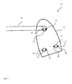
- FIG. 2 shows an enlarged view of a skid 14 with a first roller 18 and a second, further roller 20.
- the upper block arrow indicates that the skid 14 on the housing 12 of the vacuum cleaner is mounted rotatable or pivotable.
- an axle 22, more precisely a steering axle 22, is provided, which engages in a not shown, but known manner in a corresponding recess in the housing 12.
- the first and second rollers 18, 20 are arranged offset in height on the skid 14, wherein the first roller 18 is positioned lower than the second roller 20 and thus is normally in contact with the respective substrate.
- the second roller 20 is positioned higher in comparison to the first roller 18, wherein the distance between the two below the two rollers 18, 20 attaching horizontal auxiliary lines, for example, in the order of one millimeter to five millimeters.
- FIG. 3 shows in the upper area essentially the representation FIG. 1 and in the lower part of a schematically simplified illustration of the same vacuum cleaner 10 in a side view.
- a first vertical line 24 is a line through the center of gravity of the device housing 12 (centroid line 24).
- a second vertical line 26 is a line through the first rollers 18 facing the direction of gravity 24 of the draw direction. When the housing 12 has only the first rollers 18 on its skids 14, this second vertical line 26 defines a tilting axis.
- the vacuum cleaner 10 on at least one skid 14, namely usually the front skid 14, or all skids 14 next to the first roller 18 has a second roller 20 defines a line through which compared to the centroid 24 of the pulling direction facing second rollers 20, the tilting axis in FIG. 3 with a third vertical line 28 is located.
- the second and third lines 26, 28 are referred to as first and second tilting axis 26, 28. It can be seen the greater distance between the effective due to the second rollers 20 second tilting axis 28 to the center of gravity line 24.
- a vacuum cleaner 10 with rollers 18, 20 is indicated, to improve the tilting stability of the appliance housing 12 of the vacuum cleaner 10 in addition to a first runner 18 conventionally present on at least one runner 14 a further roller 20 is provided, which faces the roller 18 on the skid 14 in the circumferential direction and acts with respect to the Kippfestmaschine a device housing 12 as a support wheel.
Landscapes
- Engineering & Computer Science (AREA)
- Mechanical Engineering (AREA)
- Electric Suction Cleaners (AREA)
- Motorcycle And Bicycle Frame (AREA)
Applications Claiming Priority (1)
| Application Number | Priority Date | Filing Date | Title |
|---|---|---|---|
| DE102012105596.3A DE102012105596A1 (de) | 2012-06-27 | 2012-06-27 | Bodenstaubsauger mit Laufrollen |
Publications (2)
| Publication Number | Publication Date |
|---|---|
| EP2679128A2 true EP2679128A2 (fr) | 2014-01-01 |
| EP2679128A3 EP2679128A3 (fr) | 2018-01-24 |
Family
ID=48874239
Family Applications (1)
| Application Number | Title | Priority Date | Filing Date |
|---|---|---|---|
| EP13401060.2A Withdrawn EP2679128A3 (fr) | 2012-06-27 | 2013-06-18 | Aspirateur de sol avec galets de roulement |
Country Status (2)
| Country | Link |
|---|---|
| EP (1) | EP2679128A3 (fr) |
| DE (1) | DE102012105596A1 (fr) |
Citations (2)
| Publication number | Priority date | Publication date | Assignee | Title |
|---|---|---|---|---|
| DE10320080A1 (de) | 2003-05-05 | 2004-12-02 | BSH Bosch und Siemens Hausgeräte GmbH | Fahrbarer Staubsauger |
| DE102008017736A1 (de) | 2008-04-07 | 2009-10-08 | Miele & Cie. Kg | Bodenstaubsauger mit Rädern |
Family Cites Families (5)
| Publication number | Priority date | Publication date | Assignee | Title |
|---|---|---|---|---|
| GB461533A (en) * | 1935-07-09 | 1937-02-18 | Electrolux Ltd | Improvements in or relating to vacuum cleaners |
| DE7906217U1 (de) * | 1979-03-07 | 1979-05-31 | Rudolf Wanzl Kg,8874 Leipheim | Tragrolle mit bremsvorrichtung |
| US20120084939A1 (en) * | 2009-11-25 | 2012-04-12 | Kim Eung Dal | Canister type vacuum cleaner |
| US8214970B2 (en) * | 2009-12-15 | 2012-07-10 | General Electric Company | Wheel system with lifter apparatus |
| EP2676590A1 (fr) * | 2012-06-19 | 2013-12-25 | Robert Thomas Metall- und Elektrowerke GmbH & Co. KG | Aspirateur de sol doté d'au moins une unité à roulettes rotative intégrée |
-
2012
- 2012-06-27 DE DE102012105596.3A patent/DE102012105596A1/de not_active Withdrawn
-
2013
- 2013-06-18 EP EP13401060.2A patent/EP2679128A3/fr not_active Withdrawn
Patent Citations (2)
| Publication number | Priority date | Publication date | Assignee | Title |
|---|---|---|---|---|
| DE10320080A1 (de) | 2003-05-05 | 2004-12-02 | BSH Bosch und Siemens Hausgeräte GmbH | Fahrbarer Staubsauger |
| DE102008017736A1 (de) | 2008-04-07 | 2009-10-08 | Miele & Cie. Kg | Bodenstaubsauger mit Rädern |
Also Published As
| Publication number | Publication date |
|---|---|
| DE102012105596A1 (de) | 2014-01-02 |
| EP2679128A3 (fr) | 2018-01-24 |
Similar Documents
| Publication | Publication Date | Title |
|---|---|---|
| DE60211493T2 (de) | Rollbare gehhilfe mit einer vorrichtung zur erleichterung des fahrens | |
| EP0287857A2 (fr) | Dispositif pour monter les escaliers, particulièrement pour les fauteuils de malades | |
| EP2954817B1 (fr) | Machine de nettoyage du sol | |
| DE4100333A1 (de) | Mechanismus zur hoeheneinstellung von bodenreinigungsgeraeten | |
| EP3150449A1 (fr) | Vehicule, en particulier compacteur ou finisseur de route | |
| EP2845530A1 (fr) | Appareil d'aspiration portable pour liquides ou mélanges liquide/air | |
| WO2016058675A1 (fr) | Véhicule présentant un châssis suspendu et logé de manière tournante | |
| DE102018113691A1 (de) | Bodenreinigungsmaschine mit Seitenschürzeneinrichtung und Verfahren zum Betreiben einer Bodenreinigungsmaschine | |
| DE102011052663A1 (de) | Laufrolle | |
| DE2724106A1 (de) | Bodenzugvorrichtung | |
| EP2679128A2 (fr) | Aspirateur de sol avec galets de roulement | |
| EP3529138A1 (fr) | Scooter comprenant un ensemble repose-pied | |
| EP0792613B1 (fr) | Embout pour aspirateur | |
| EP3548302A2 (fr) | Rouleau muni d'un dispositif de freinage | |
| DE102008011542B4 (de) | Bodenstaubsauger mit Rädern | |
| DE102008054338A1 (de) | Abstellvorrichtung für eine Dreipunktanbaumaschine | |
| EP2778287B1 (fr) | Machine de nettoyage du sol dotée d'un dispositif d'alimentation en liquide pour l'unité de nettoyage | |
| DE102018003099A1 (de) | Landwirtschaftliche Heuwerbungsmaschine | |
| DE102010031165A1 (de) | Auszugsvorrichtung für einen ausziehbaren Geschirrkorb einer Geschirrspülmaschine | |
| DE102008017736B4 (de) | Bodenstaubsauger mit Rädern | |
| DE69816351T2 (de) | Bremse für Rollstuhl | |
| EP3106566B1 (fr) | Systeme d'aspiration pour une machine de nettoyage de sol | |
| DE112014003477T5 (de) | Schneidvorrichtung und Bodenschneidanordnung | |
| EP4649877A2 (fr) | Machine de nettoyage de sol avec pied d'aspiration pivotant | |
| DE4005500A1 (de) | Haushaltgeraet mit einem schrankfoermigen gehaeuse |
Legal Events
| Date | Code | Title | Description |
|---|---|---|---|
| PUAI | Public reference made under article 153(3) epc to a published international application that has entered the european phase |
Free format text: ORIGINAL CODE: 0009012 |
|
| AK | Designated contracting states |
Kind code of ref document: A2 Designated state(s): AL AT BE BG CH CY CZ DE DK EE ES FI FR GB GR HR HU IE IS IT LI LT LU LV MC MK MT NL NO PL PT RO RS SE SI SK SM TR |
|
| AX | Request for extension of the european patent |
Extension state: BA ME |
|
| PUAL | Search report despatched |
Free format text: ORIGINAL CODE: 0009013 |
|
| 17P | Request for examination filed |
Effective date: 20171219 |
|
| AK | Designated contracting states |
Kind code of ref document: A3 Designated state(s): AL AT BE BG CH CY CZ DE DK EE ES FI FR GB GR HR HU IE IS IT LI LT LU LV MC MK MT NL NO PL PT RO RS SE SI SK SM TR |
|
| AX | Request for extension of the european patent |
Extension state: BA ME |
|
| RBV | Designated contracting states (corrected) |
Designated state(s): AL AT BE BG CH CY CZ DE DK EE ES FI FR GB GR HR HU IE IS IT LI LT LU LV MC MK MT NL NO PL PT RO RS SE SI SK SM TR |
|
| RIC1 | Information provided on ipc code assigned before grant |
Ipc: A47L 5/36 20060101AFI20171215BHEP Ipc: A47L 9/00 20060101ALI20171215BHEP |
|
| STAA | Information on the status of an ep patent application or granted ep patent |
Free format text: STATUS: THE APPLICATION HAS BEEN WITHDRAWN |
|
| 18W | Application withdrawn |
Effective date: 20190102 |