EP2679307B1 - Micro-enregistreur, notamment pour l'intégration dans une cellule d'écoulement microfluidique - Google Patents
Micro-enregistreur, notamment pour l'intégration dans une cellule d'écoulement microfluidique Download PDFInfo
- Publication number
- EP2679307B1 EP2679307B1 EP12173976.7A EP12173976A EP2679307B1 EP 2679307 B1 EP2679307 B1 EP 2679307B1 EP 12173976 A EP12173976 A EP 12173976A EP 2679307 B1 EP2679307 B1 EP 2679307B1
- Authority
- EP
- European Patent Office
- Prior art keywords
- microstorage
- actuator element
- barrier
- outlet channel
- film
- Prior art date
- Legal status (The legal status is an assumption and is not a legal conclusion. Google has not performed a legal analysis and makes no representation as to the accuracy of the status listed.)
- Active
Links
Images


Classifications
-
- B—PERFORMING OPERATIONS; TRANSPORTING
- B01—PHYSICAL OR CHEMICAL PROCESSES OR APPARATUS IN GENERAL
- B01L—CHEMICAL OR PHYSICAL LABORATORY APPARATUS FOR GENERAL USE
- B01L3/00—Containers or dishes for laboratory use, e.g. laboratory glassware; Droppers
- B01L3/50—Containers for the purpose of retaining a material to be analysed, e.g. test tubes
-
- B—PERFORMING OPERATIONS; TRANSPORTING
- B01—PHYSICAL OR CHEMICAL PROCESSES OR APPARATUS IN GENERAL
- B01L—CHEMICAL OR PHYSICAL LABORATORY APPARATUS FOR GENERAL USE
- B01L3/00—Containers or dishes for laboratory use, e.g. laboratory glassware; Droppers
- B01L3/50—Containers for the purpose of retaining a material to be analysed, e.g. test tubes
- B01L3/502—Containers for the purpose of retaining a material to be analysed, e.g. test tubes with fluid transport, e.g. in multi-compartment structures
- B01L3/5027—Containers for the purpose of retaining a material to be analysed, e.g. test tubes with fluid transport, e.g. in multi-compartment structures by integrated microfluidic structures, i.e. dimensions of channels and chambers are such that surface tension forces are important, e.g. lab-on-a-chip
-
- B—PERFORMING OPERATIONS; TRANSPORTING
- B01—PHYSICAL OR CHEMICAL PROCESSES OR APPARATUS IN GENERAL
- B01L—CHEMICAL OR PHYSICAL LABORATORY APPARATUS FOR GENERAL USE
- B01L3/00—Containers or dishes for laboratory use, e.g. laboratory glassware; Droppers
- B01L3/50—Containers for the purpose of retaining a material to be analysed, e.g. test tubes
- B01L3/502—Containers for the purpose of retaining a material to be analysed, e.g. test tubes with fluid transport, e.g. in multi-compartment structures
- B01L3/5027—Containers for the purpose of retaining a material to be analysed, e.g. test tubes with fluid transport, e.g. in multi-compartment structures by integrated microfluidic structures, i.e. dimensions of channels and chambers are such that surface tension forces are important, e.g. lab-on-a-chip
- B01L3/50273—Containers for the purpose of retaining a material to be analysed, e.g. test tubes with fluid transport, e.g. in multi-compartment structures by integrated microfluidic structures, i.e. dimensions of channels and chambers are such that surface tension forces are important, e.g. lab-on-a-chip characterised by the means or forces applied to move the fluids
-
- B—PERFORMING OPERATIONS; TRANSPORTING
- B01—PHYSICAL OR CHEMICAL PROCESSES OR APPARATUS IN GENERAL
- B01L—CHEMICAL OR PHYSICAL LABORATORY APPARATUS FOR GENERAL USE
- B01L2300/00—Additional constructional details
- B01L2300/08—Geometry, shape and general structure
- B01L2300/0809—Geometry, shape and general structure rectangular shaped
-
- B—PERFORMING OPERATIONS; TRANSPORTING
- B01—PHYSICAL OR CHEMICAL PROCESSES OR APPARATUS IN GENERAL
- B01L—CHEMICAL OR PHYSICAL LABORATORY APPARATUS FOR GENERAL USE
- B01L2300/00—Additional constructional details
- B01L2300/12—Specific details about materials
- B01L2300/123—Flexible; Elastomeric
-
- Y—GENERAL TAGGING OF NEW TECHNOLOGICAL DEVELOPMENTS; GENERAL TAGGING OF CROSS-SECTIONAL TECHNOLOGIES SPANNING OVER SEVERAL SECTIONS OF THE IPC; TECHNICAL SUBJECTS COVERED BY FORMER USPC CROSS-REFERENCE ART COLLECTIONS [XRACs] AND DIGESTS
- Y10—TECHNICAL SUBJECTS COVERED BY FORMER USPC
- Y10T—TECHNICAL SUBJECTS COVERED BY FORMER US CLASSIFICATION
- Y10T137/00—Fluid handling
- Y10T137/8593—Systems
Definitions
- the invention relates to a micro-accumulator, in particular for integration into a microfluidic flow cell, with a fluid-containing storage space, which communicates with a discharge channel for the fluid, in which a repealing barrier for the fluid is formed, and with means for lifting the barrier without pressurization of the barrier by the fluid comprising an actuator element for mechanically destroying the barrier.
- Micro memory are eg from the WO 2009/071078 A1 known.
- a storage space and an outlet channel of this known micro memory form two arranged on a plate-shaped substrate films which are welded together under the limitation of the storage space and the outlet channel and / or glued.
- the film facing away from the substrate has a dome-like shape.
- a line-shaped transversely to the outlet channel extending welding or / and bonding of the films serves as the storage space hermetically sealing barrier.
- the storage space forms a deep-drawn expansion of the film facing away from the substrate. In order to open the storage space, it is compressed with deformation of the film until such a pressure builds up at the intended as a predetermined breaking point lock that ruptures the predetermined breaking point.
- the one-piece substrate forms part of a fluid processing device (flow cell) which, in addition to one or more micro-accumulators, may comprise further fluid-conveying elements.
- a fluid processing device flow cell
- micro-accumulators may comprise further fluid-conveying elements.
- these include elements for the supply of liquid or gaseous samples, mixing elements, pumps, valves, filters for separating components of a fluid, temperature control chambers, detection chambers, Lateral flow test strips, transport channels and waste chambers used singly or in combination for the analysis and / or synthesis of fluids for medical and pharmaceutical purposes or for analytical processes such as immunoassays or genetic assays.
- the fluid pressure required to remove the barrier causes the fluid to shoot out of the storage space at the first moment after the exit channel has been opened at a high flow rate.
- a subset of the stored fluid leaves in this way uncontrolled and undosed the memory space. If the flow cell is intended for reactions which require defined flow rates of supplied reagents, this subset is lost and thus the contents of the micro memory are not fully usable.
- a micro memory of the type mentioned above goes from the WO 2009/152952 A1 out.
- the barrier in the outlet channel of this known micro-memory is formed by a barrier film passing through the outlet channel. To break up the barrier, the barrier film is stretched by an actuator until it ruptures releasing the outlet channel.
- the invention has for its object to provide a new micro store of the type mentioned above, which allows a controlled from the beginning and metered removal of the stored fluid.
- the micro-accumulator according to the invention that achieves this object is characterized in that the barrier is formed by welding or / and bonding opposing boundary walls of the outlet channel and the actuator causes the separation of the welding or / and bonding between the boundary walls.
- the lock can be canceled while leaving the entire amount of memory in the memory space. From the beginning, after the barrier has been opened, a controlled and metered removal of fluid from the reservoir can take place.
- the means for lifting the barrier according to the invention comprise an actuator, which eliminates the welding or / and bonding of the opposing boundary walls of the exit channel.
- At least one of these two boundary walls may consist of a flexible film.
- the actuator element can be provided for the arrangement outside the outlet channel or within the outlet channel on the side facing away from the storage space of the barrier.
- the at least one flexible film is arranged on a substrate and the actuator element can be pressed against the film through a passage opening in the substrate, thereby producing a break-off force which releases the barrier.
- the outlet channel may be formed between two flexible films adjacent to each other and the film facing the substrate may be connected to the substrate, wherein the actuator element lifts the films apart by generating the demolition force across the channel width by expanding them with different radii.
- the actuator element which is preferably in the form of a pin, expediently acts on the film on the side of the barrier which faces away from the storage space. In particular, this is done in an adjoining the outlet channel area in which the film is connected neither to the substrate nor another possibly existing film.
- the actuator element can be part of a device for operating the micro-storage unit or flow cell.
- the actuator element arranged within the outlet channel has an impact element that can be extended against the barrier by deformation of the actuator element, which opens the barrier away from the side facing away from the storage space.
- this actuator element is arc-shaped and the impact element can be extended by stretching the sheet.
- the actuator element can be held in a form-fitting manner in an expansion of the film forming the boundary wall of the outlet channel at an end facing away from the butt end, so that essentially only the butt member of the element provided for opening the barrier is moved during the stretching of the arch.
- the actuator element comprises a lever connected to the outside of the flexible film for producing a break-off force which releases the barrier.
- the actuator element may comprise a rod element forming two such levers, crossing the outlet channel, the end of which is rotatable by bending the rod element around a pivot point formed by the substrate to form the tear-off force.
- the ends of the rod could protrude beyond edges of the substrate, in a preferred embodiment two openings are provided in the substrate into which the ends are pressable under flexure of the rod member.
- the actuator element provided within the outlet channel and / or the region of the outlet channel in the flow direction behind the barrier can be associated with a dry reagent which is resuspended when the fluid flows out.
- the transport of the fluids out of the storage space can be carried out alternatively by deformation of a film forming the storage by application of pneumatic or / and hydraulic pressure.
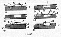
- Fig. 12 Reference is made, where in subfigures (a) to (f) conventional micro memory integrated into a microfluidic flow cell with a substrate 1 are shown.
- the substrate is made of a plastic and is made by injection molding.
- a storage space 2 for a fluid between the substrate 1 and a flexible film 3 welded or bonded to the substrate is formed by a depression in the film (FIG. Fig. 12a ) or in the substrate ( Fig. 12b to d) formed.
- a barrier 6 for the fluid is formed in the storage space 2, through which the storage space 2 is hermetically sealed.
- Fig. 12d are two outlet channels, each with a barrier 6 or 6 'is formed, which delimits the storage space 2 against a feed channel 27 and a discharge channel 28.
- Fig. 12e and f is the storage space 2 between the film 3 and another connected to the substrate 1 film 7.
- the film 3 is with the film 7, in the same manner as the film 3 to the substrate 1 in Examples 12a-d, welded, or / and glued.
- An outlet channel 4 with a barrier 6 is as in formed in the preceding examples by omitting the welding or gluing in the region of the channel.
- the storage space 2 is formed between a depression of the film 3 and a depression of the film 7, the depression of the film 7 projecting into a depression formed in the substrate 1.
- a channel-shaped storage space 2 is additionally provided with a filling channel 29 and a venting channel 30.
- the fluid to be stored is entered by dispensing or by pumping into the filling channel 29 and the storage space completely filled. Air in the storage space can escape via the vent passage 30.
- the filling channel 29 and the venting channel 30 are hermetically sealed by means of a bottom foil 31 glued or welded to the substrate 1. The bottom foil 31 simultaneously serves as a fluid-tight cover of the transport channel 5.
- the foils 3, 7 are preferably made of a plastic, of aluminum or of a plastic-aluminum composite.
- a plastic-aluminum composite foil e.g. PP, PE, COC, COP, PC, PMMA and PEEK come into consideration.
- the storage space 2 is emptied by displacing the liquid or gaseous fluid contained therein by deformation of the film 3.
- the fluid When the fluid is displaced, it penetrates into the unconnected channel area between the film 3 and the substrate 1 or between the film 3 and the other film 7 and is under pressure to the barrier 6 at. If the fluid pressure is sufficiently high, the barrier 6 breaks and the fluid continues to penetrate, with the opening of a channel cross-section, until the fluid flow reaches the channel 5.
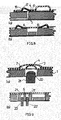
- FIG. 1 An in Fig. 1 shown, the example of Fig. 12a corresponding micro memory with a substrate 1 and a storage space 2, which is formed by a welded to the substrate 1 and / or bonded film 3 between the film 3 and the substrate 1, then points to an outlet channel 4, which penetrates the substrate 1 Channel 5 ends, a further region 8, in which the film 3 is not welded as in the outlet channel 4 with the substrate 1 and / or glued.
- This region 8 is aligned with a passage opening 9 in the substrate 1.
- an elastic, welded to the substrate 1 and / or bonded membrane 11 is inserted.
- a film 12 covers the substrate on the opposite side of the storage space 2 under closure of a portion of the channel 5 from.
- Operating equipment to be used comprises, in addition to an actuator 13 for deforming the film 3 in the region of the storage space 2, a pin-shaped actuator element 14 which is inserted into the opening 9 in the substrate 1 and against the elastic membrane 11 under deformation of the membrane 11 can be pressed. With the deformation of the membrane 11, the film 3 is raised in the adjoining the channel 4 unconnected region 8, wherein this increase continues into the channel 4 into it. This creates a tearing force which breaks the barrier 6.
- the storage space 2 can now be emptied dosed by means of the actuator 13.
- the film 3, which bears against the substrate 1 before the emptying of the storage space 2 is raised by the penetration of the fluid to form a channel cross-section. From the beginning, a metered delivery of fluid from the storage space 2 is possible using the entire storage contents.
- a further actuator element 15 which can be attached to the film 3 by the side of the micro-memory that is opposite the actuator element 14, presses after opening the barrier 6, the film 3 against the substrate 1, so that fluid from the channel 4 can not penetrate into the unconnected region 8.
- the pin-shaped, arranged outside the outlet channel 4 actuator element 14 goes out of the Fig. 4 to 7 a memory of Fig. 12e corresponding embodiment with a disposed within an outlet channel 4 actuator element 16 forth.
- This in Fig. 5 separately shown actuator element 16 is accommodated in a molding 17 of the film 3, wherein the molding 17 is made together with the provided for forming the storage space 2 molding by deep drawing.
- the actuator element 16 is arcuately formed with an expiring to a bow end towards impact wedge 18.
- the actuator element 16 has a groove on its upper or lower side, in the present case on its upper side, the channel 26.
- the channel forms a channel region in the pressed-on and stretched state, through the actuator element 16 and the pressed-on film 3 or film 7 is limited and through which the fluid from the storage space 2 can get into the channel 5.
- the actuator element 16 is preferably made of plastic, in particular of the same plastic as the substrate, and is produced by injection molding.
- the actuator element 16 may be made of a shape memory alloy or a bimetal, wherein in these cases, the stretching of the actuator element takes place by supplying heat.
- an operator device comprises an actuator 13 for deforming the film 3 in the region of the storage space 2, a further actuator 19, through which the arcuate actuator element 16 compresses and stretch, so that the impact wedge 18 pierces the barrier 6, while the other end the arcuate actuator element is held positively in the formation 17.
- fluid can be transferred from the storage space 2 into the channel 5 with the aid of the actuator 13.
- the actuator 19 can be rigidly connected to a clamping device which is part of a device for operating the flow cell.
- a clamping device which is part of a device for operating the flow cell.
- the actuator element 16 receiving formation 17, which is located in the channel 4 can be used to receive next to the actuator element 16, a reagent, in particular dry reagent is at a in Fig. 8a
- the molding 17 is laid essentially in a region which adjoins the end of the channel 4, in which the films 3 and 4 are not welded or glued together.
- Fig. 8b two outlet channels with a lock 6 and 6 'are provided, which can be destroyed by an actuator element 16 or 16'. After destruction of both locks, the memory can be emptied by pneumatic or hydraulic pressure without deformation of the storage space limiting film.
- a through hole 20 may be formed in the substrate 1, in which a film 7 in the region of the channel 4 expanding actuator element 21 is inserted, wherein the expanded film 7, the film 3 near the barrier (in Fig. 9a not shown) and generates a tearing force.
- one of the passage opening 20 corresponding opening 20 'for an actuator element 21' in the flow direction may also be provided in front of the barrier 6.
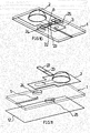
- One in the 10 and 11 Micro memory shown has a rod-shaped actuator element 22, which crosses the region of the outlet channel 4, in which the film 3 is not connected to the substrate 1, and bonded to the outside of the film 3 at 23 and / or welded.
- Through holes 24 and 25 in the substrate 1 allow a bending of the actuator element by pressing its ends in the Through holes 24,25, wherein the lock 6 canceling tear-off force is generated.
Landscapes
- Chemical & Material Sciences (AREA)
- Health & Medical Sciences (AREA)
- Analytical Chemistry (AREA)
- General Health & Medical Sciences (AREA)
- Hematology (AREA)
- Clinical Laboratory Science (AREA)
- Chemical Kinetics & Catalysis (AREA)
- Dispersion Chemistry (AREA)
- Micromachines (AREA)
- Automatic Analysis And Handling Materials Therefor (AREA)
- Apparatus Associated With Microorganisms And Enzymes (AREA)
Claims (13)
- Microréservoir, en particulier pour l'intégration dans une cellule d'écoulement microfluidique, présentant une chambre de réservoir (2) recevant un fluide, qui est reliée à un canal de sortie (4) pour le fluide, dans lequel est formé un dispositif de blocage (6) pouvant être supprimé pour le fluide et présentant des moyens pour supprimer le dispositif de blocage (6) sans solliciter le dispositif de blocage (6) par la pression du fluide, qui comprennent un élément d'actionnement (14 ; 16 ; 21 ; 22) pour la destruction mécanique du dispositif de blocage (6) caractérisé en ce que le dispositif de blocage (6) est formé par soudure et/ou collage de parois de délimitation opposées l'une à l'autre du canal de sortie (4) et l'élément d'actionnement (14 ; 16 ; 21 ; 22) provoque la séparation de la soudure et/ou du collage entre les parois de délimitation.
- Microréservoir selon la revendication 1, caractérisé en ce qu'au moins une des deux parois de délimitation est formée par une feuille souple (3, 7).
- Microréservoir selon la revendication 1 ou 2, caractérisé en ce que l'élément d'actionnement (14 ; 16 ; 21 ; 22) est destiné à être disposé en dehors du canal de sortie (4) ou à l'intérieur du canal de sortie (4), à l'intérieur de préférence sur le côté du dispositif de blocage (6) opposé à la chambre de réservoir (2).
- Microréservoir selon la revendication 2 ou 3, caractérisé en ce que ladite au moins une feuille souple (3, 7) est disposée sur un substrat (1) et l'élément d'actionnement (14 ; 21) peut être pressé contre la feuille (3, 7) au travers d'une ouverture de passage (9, 20) dans le substrat (1) avec génération d'une force de déchirement supprimant le dispositif de blocage (6).
- Microréservoir selon la revendication 4, caractérisé en ce que le canal de sortie (4) est formé entre deux feuilles souples (3, 7) placées l'une contre l'autre et la feuille (7) orientée vers le substrat (1) est reliée au substrat, l'élément d'actionnement (21) soulevant les feuilles (3, 7) l'une de l'autre sur la largeur du canal avec génération de la feuille de déchirement.
- Microréservoir selon la revendication 5, caractérisé en ce que l'élément d'actionnement (14 ; 21) peut être pressé contre la feuille (3, 7) sur le côté du dispositif de blocage (6) opposé à la chambre de réservoir (2), en particulier dans une zone (8) rattachée au canal de sortie (4).
- Microréservoir selon l'une quelconque des revendications 3 à 6, caractérisé en ce que l'élément d'actionnement (14 ; 21) est un constituant d'un appareil pour le fonctionnement du microréservoir ou de la cellule d'écoulement.
- Microréservoir selon l'une quelconque des revendications 3 à 7, caractérisé en ce que l'élément d'actionnement (16) disposé à l'intérieur du canal de sortie (4) présente un élément d'impact (17) pouvant être déployé par déformation de l'élément d'actionnement (16) contre le dispositif de blocage (6), l'élément d'actionnement (16) étant de préférence conçu en forme d'arc et l'élément d'impact (17) pouvant être déployé par étirement de l'arc.
- Microréservoir selon la revendication 8, caractérisé en ce que l'élément d'actionnement (16) est maintenu dans un élargissement (17) de la feuille (3) formant la paroi de délimitation du canal de sortie (4) par fermeture géométrique en une extrémité opposée à l'élément d'impact (17).
- Microréservoir selon l'une quelconque des revendications 2 à 9, caractérisé en ce que l'élément d'actionnement (22) comprend un levier relié à la face externe de la feuille souple (3) pour générer une force de déchirement supprimant le dispositif de blocage (6).
- Microréservoir selon la revendication 10, caractérisé en ce que l'élément d'actionnement comprend un élément de tige (22) formant deux de ces leviers, croisant le canal de sortie (4), dont les extrémités peuvent être tournées, avec génération de la force de déchirement par flexion de l'élément de tige (22), autour d'un point de rotation formé par le substrat (1), les deux extrémités pouvant de préférence respectivement être pressées dans une ouverture (24, 25) dans le substrat (1).
- Microréservoir selon l'une quelconque des revendications 3 à 11, caractérisé en ce que l'élément d'actionnement (16) disposé à l'intérieur du canal de sortie (4) ou la zone du canal de sortie (4) dans le sens d'écoulement en aval du dispositif de blocage (6) est associé(e) à un réactif sec.
- Microréservoir selon l'une quelconque des revendications 1 à 12, caractérisé en ce que le fluide peut être transporté hors de la chambre de réservoir (2) par une pression pneumatique et/ou hydraulique.
Priority Applications (2)
| Application Number | Priority Date | Filing Date | Title |
|---|---|---|---|
| EP12173976.7A EP2679307B1 (fr) | 2012-06-28 | 2012-06-28 | Micro-enregistreur, notamment pour l'intégration dans une cellule d'écoulement microfluidique |
| US13/917,284 US9108192B2 (en) | 2012-06-28 | 2013-06-13 | Micro reservoir, particularly for integration in a microfluidic flow cell |
Applications Claiming Priority (1)
| Application Number | Priority Date | Filing Date | Title |
|---|---|---|---|
| EP12173976.7A EP2679307B1 (fr) | 2012-06-28 | 2012-06-28 | Micro-enregistreur, notamment pour l'intégration dans une cellule d'écoulement microfluidique |
Publications (2)
| Publication Number | Publication Date |
|---|---|
| EP2679307A1 EP2679307A1 (fr) | 2014-01-01 |
| EP2679307B1 true EP2679307B1 (fr) | 2015-08-12 |
Family
ID=46458213
Family Applications (1)
| Application Number | Title | Priority Date | Filing Date |
|---|---|---|---|
| EP12173976.7A Active EP2679307B1 (fr) | 2012-06-28 | 2012-06-28 | Micro-enregistreur, notamment pour l'intégration dans une cellule d'écoulement microfluidique |
Country Status (2)
| Country | Link |
|---|---|
| US (1) | US9108192B2 (fr) |
| EP (1) | EP2679307B1 (fr) |
Cited By (5)
| Publication number | Priority date | Publication date | Assignee | Title |
|---|---|---|---|---|
| US9662650B2 (en) | 2013-07-29 | 2017-05-30 | Atlas Genetics Limited | Fluidic cartridge and method for processing a liquid sample |
| US9816135B2 (en) | 2013-07-29 | 2017-11-14 | Atlas Genetics Limited | Fluidic cartridge for nucleic acid amplification and detection |
| US9908114B2 (en) | 2013-07-29 | 2018-03-06 | Atlas Genetics Limited | Cartridge, cartridge reader and method for preventing reuse of the cartridge |
| US9993818B2 (en) | 2013-07-29 | 2018-06-12 | Atlas Genetics Limited | Valve which depressurises, and a valve system |
| US9999883B2 (en) | 2013-07-29 | 2018-06-19 | Atlas Genetics Limited | System and method for processing fluid in a fluidic cartridge |
Families Citing this family (19)
| Publication number | Priority date | Publication date | Assignee | Title |
|---|---|---|---|---|
| AU2013334189B2 (en) | 2012-10-24 | 2018-08-02 | Genmark Diagnostics, Inc. | Integrated multiplex target analysis |
| US20140322706A1 (en) | 2012-10-24 | 2014-10-30 | Jon Faiz Kayyem | Integrated multipelx target analysis |
| JP6351702B2 (ja) | 2013-03-15 | 2018-07-04 | ジェンマーク ダイアグノスティクス, インコーポレイテッド | 変形可能流体容器を操作するためのシステム、方法、および装置 |
| USD881409S1 (en) | 2013-10-24 | 2020-04-14 | Genmark Diagnostics, Inc. | Biochip cartridge |
| US9498778B2 (en) | 2014-11-11 | 2016-11-22 | Genmark Diagnostics, Inc. | Instrument for processing cartridge for performing assays in a closed sample preparation and reaction system |
| US9610579B2 (en) | 2014-01-07 | 2017-04-04 | Daktari Diagnostics, Inc. | Fluid delivery devices, systems, and methods |
| EP2962758B1 (fr) | 2014-07-01 | 2017-07-19 | ThinXXS Microtechnology AG | Cellule d'écoulement dotée d'une zone de stockage et d'un canal de transport pouvant s'ouvrir à un point de rupture |
| US9598722B2 (en) | 2014-11-11 | 2017-03-21 | Genmark Diagnostics, Inc. | Cartridge for performing assays in a closed sample preparation and reaction system |
| US10005080B2 (en) | 2014-11-11 | 2018-06-26 | Genmark Diagnostics, Inc. | Instrument and cartridge for performing assays in a closed sample preparation and reaction system employing electrowetting fluid manipulation |
| WO2017095845A1 (fr) * | 2015-12-01 | 2017-06-08 | Illumina, Inc. | Mécanismes et procédés de stockage et de distribution de liquides |
| GB201615452D0 (en) * | 2016-09-12 | 2016-10-26 | Fluidic Analytics Ltd | Improvements in or relating to valves for microfluidics devices |
| US10046322B1 (en) | 2018-03-22 | 2018-08-14 | Talis Biomedical Corporation | Reaction well for assay device |
| US11008627B2 (en) | 2019-08-15 | 2021-05-18 | Talis Biomedical Corporation | Diagnostic system |
| EP3912721A1 (fr) | 2020-05-22 | 2021-11-24 | Thinxxs Microtechnology Ag | Cellule d'écoulement comprenant un dispositif de blocage à rupture |
| US20240351040A1 (en) * | 2021-11-01 | 2024-10-24 | Novel Microdevices, Inc. | Apparatus for containing and dispensing reagent into a microfluidic cartridge for use in point-of-care devices |
| US20230312209A1 (en) * | 2022-04-05 | 2023-10-05 | 10X Genomics, Inc. | Blister packs and uses thereof |
| DE102022211170A1 (de) * | 2022-10-21 | 2024-05-02 | Robert Bosch Gesellschaft mit beschränkter Haftung | Kompartiment mit Versiegelung |
| DE102022211171A1 (de) * | 2022-10-21 | 2024-05-02 | Robert Bosch Gesellschaft mit beschränkter Haftung | Versiegelung für eine mikrofluidische Kammer |
| LU504851B1 (de) * | 2023-08-02 | 2025-02-03 | Thinxxs Microtechnology Gmbh | Mikrofluidische Flusszelle und Verfahren zur Herstellung einer mikrofluidischen Flusszelle |
Family Cites Families (11)
| Publication number | Priority date | Publication date | Assignee | Title |
|---|---|---|---|---|
| US3635376A (en) * | 1970-06-05 | 1972-01-18 | Hellstrom Harold R | Quick-open flexible package |
| US4592493A (en) * | 1984-10-15 | 1986-06-03 | Unette Corporation | Reclosable dispenser |
| FR2782935B3 (fr) * | 1998-09-08 | 2000-10-20 | Biomerieux Sa | Dispositif permettant des reactions, systeme de transfert entre dispositifs et procede de mise en oeuvre d'un tel systeme |
| US7198759B2 (en) * | 2002-07-26 | 2007-04-03 | Applera Corporation | Microfluidic devices, methods, and systems |
| US7135147B2 (en) * | 2002-07-26 | 2006-11-14 | Applera Corporation | Closing blade for deformable valve in a microfluidic device and method |
| FR2856046B1 (fr) * | 2003-06-16 | 2005-07-29 | Biomerieux Sa | Microvanne fluidique a ouverture par commande electrique |
| DE10336850B4 (de) * | 2003-08-11 | 2006-10-26 | Thinxxs Gmbh | Mikrospeicher |
| DE102007059533A1 (de) | 2007-12-06 | 2009-06-10 | Thinxxs Microtechnology Ag | Mikrofluidische Speichervorrichtung |
| EP2300164B1 (fr) * | 2008-06-19 | 2018-03-14 | Boehringer Ingelheim Microparts GmbH | Contenant à indicateur de débit |
| DE102011015184B4 (de) * | 2010-06-02 | 2013-11-21 | Thinxxs Microtechnology Ag | Vorrichtung für den Transport kleiner Volumina eines Fluids, insbesondere Mikropumpe oder Mikroventil |
| DE102011003856B4 (de) * | 2011-02-09 | 2020-06-18 | Robert Bosch Gmbh | Mikrosystem für fluidische Anwendungen sowie Herstellungsverfahren und Benutzungsverfahren für ein Mikrosystem für fluidische Anwendungen |
-
2012
- 2012-06-28 EP EP12173976.7A patent/EP2679307B1/fr active Active
-
2013
- 2013-06-13 US US13/917,284 patent/US9108192B2/en active Active
Cited By (5)
| Publication number | Priority date | Publication date | Assignee | Title |
|---|---|---|---|---|
| US9662650B2 (en) | 2013-07-29 | 2017-05-30 | Atlas Genetics Limited | Fluidic cartridge and method for processing a liquid sample |
| US9816135B2 (en) | 2013-07-29 | 2017-11-14 | Atlas Genetics Limited | Fluidic cartridge for nucleic acid amplification and detection |
| US9908114B2 (en) | 2013-07-29 | 2018-03-06 | Atlas Genetics Limited | Cartridge, cartridge reader and method for preventing reuse of the cartridge |
| US9993818B2 (en) | 2013-07-29 | 2018-06-12 | Atlas Genetics Limited | Valve which depressurises, and a valve system |
| US9999883B2 (en) | 2013-07-29 | 2018-06-19 | Atlas Genetics Limited | System and method for processing fluid in a fluidic cartridge |
Also Published As
| Publication number | Publication date |
|---|---|
| US9108192B2 (en) | 2015-08-18 |
| EP2679307A1 (fr) | 2014-01-01 |
| US20140000735A1 (en) | 2014-01-02 |
Similar Documents
| Publication | Publication Date | Title |
|---|---|---|
| EP2679307B1 (fr) | Micro-enregistreur, notamment pour l'intégration dans une cellule d'écoulement microfluidique | |
| EP2962758B1 (fr) | Cellule d'écoulement dotée d'une zone de stockage et d'un canal de transport pouvant s'ouvrir à un point de rupture | |
| EP2398589B1 (fr) | Cellule d'écoulement avec réservoir intégré de fluides | |
| EP2225037A1 (fr) | Dispositif de stockage microfluidique | |
| EP2454170B1 (fr) | Reservoir de fluide | |
| EP2611594B1 (fr) | Procedé de fabrication d'un dispositif microfluidique et appareil de laminage qui y sont associés | |
| DE102007055315B4 (de) | Luftkammer-Verpackungsfolie mit Luftstoppventil vom Schnittlochtyp, und Luftstoppventil vom Schnittlochtyp | |
| EP3393661B1 (fr) | Dispositif microfluidique et procédé de fonctionnement d'un dispositif microfluidique | |
| EP2637933B1 (fr) | Procede de remplissage d'un emballage a blister avec un liquide | |
| EP2905079A1 (fr) | Dispositif de stockage préalable d'un fluide dans un système micro-fluidique, procédé de fonctionnement et procédé de fabrication d'un tel dispositif | |
| EP2099567A1 (fr) | Dispositif de réception ou de manipulation d'un liquide | |
| DE102011003856A1 (de) | Mikrosystem für fluidische Anwendungen sowie Herstellungsverfahren und Benutzungsverfahren für ein Mikrosystem für fluidische Anwendungen | |
| EP3406340B1 (fr) | Cellule d'écoulement comprenant un élément de boîtier | |
| DE102015205906B4 (de) | Bevorratungseinheit, Verfahren zum Herstellen einer Bevorratungseinheit und Verfahren zum Freisetzen eines in einer Bevorratungseinheit gelagerten Fluids | |
| DE102014202342A1 (de) | Vorrichtung zum Vorlagern eines Fluids in einem mikrofluidischen System, Verfahren zum Betreiben und Verfahren zum Herstellen einer solchen Vorrichtung | |
| EP2754495A2 (fr) | Système de canaux microfluidique doté d'un dispositif de collecte de bulles et procédé d'élimination de bulles de gaz | |
| EP2729251B1 (fr) | Structure microfluidique avec des cavités | |
| DE202014104510U1 (de) | Vorrichtung zum Vorlagern eines Fluids in einem mikrofluidischen System | |
| DE202018105661U1 (de) | Kartusche für ein Misch- und Austragssystem | |
| DE102018117161A1 (de) | Behälterverschluss mit einer Standardkapsel | |
| DE202021103913U1 (de) | Folienkartusche, Stützhülse und Kartuschensystem | |
| EP2624955A1 (fr) | Plateforme microfluidique | |
| LU504851B1 (de) | Mikrofluidische Flusszelle und Verfahren zur Herstellung einer mikrofluidischen Flusszelle | |
| DE102015225837A1 (de) | Folienbeutel für ein mikrofluidisches Analysesystem, mikrofluidisches Analysesystem, Verfahren zum Herstellen und Verfahren zum Betreiben eines mikrofluidischen Analysesystems | |
| DE102013209645A1 (de) | Ventilvorrichtung für eine Fluidbereitstellungseinheit und Verfahren zum Betreiben einer Ventilvorrichtung für eine Fluidbereitstellungseinheit |
Legal Events
| Date | Code | Title | Description |
|---|---|---|---|
| PUAI | Public reference made under article 153(3) epc to a published international application that has entered the european phase |
Free format text: ORIGINAL CODE: 0009012 |
|
| AK | Designated contracting states |
Kind code of ref document: A1 Designated state(s): AL AT BE BG CH CY CZ DE DK EE ES FI FR GB GR HR HU IE IS IT LI LT LU LV MC MK MT NL NO PL PT RO RS SE SI SK SM TR |
|
| AX | Request for extension of the european patent |
Extension state: BA ME |
|
| 17P | Request for examination filed |
Effective date: 20140701 |
|
| RBV | Designated contracting states (corrected) |
Designated state(s): AL AT BE BG CH CY CZ DE DK EE ES FI FR GB GR HR HU IE IS IT LI LT LU LV MC MK MT NL NO PL PT RO RS SE SI SK SM TR |
|
| GRAP | Despatch of communication of intention to grant a patent |
Free format text: ORIGINAL CODE: EPIDOSNIGR1 |
|
| INTG | Intention to grant announced |
Effective date: 20150306 |
|
| GRAS | Grant fee paid |
Free format text: ORIGINAL CODE: EPIDOSNIGR3 |
|
| GRAA | (expected) grant |
Free format text: ORIGINAL CODE: 0009210 |
|
| AK | Designated contracting states |
Kind code of ref document: B1 Designated state(s): AL AT BE BG CH CY CZ DE DK EE ES FI FR GB GR HR HU IE IS IT LI LT LU LV MC MK MT NL NO PL PT RO RS SE SI SK SM TR |
|
| REG | Reference to a national code |
Ref country code: GB Ref legal event code: FG4D Free format text: NOT ENGLISH |
|
| REG | Reference to a national code |
Ref country code: CH Ref legal event code: EP |
|
| REG | Reference to a national code |
Ref country code: AT Ref legal event code: REF Ref document number: 741625 Country of ref document: AT Kind code of ref document: T Effective date: 20150815 |
|
| REG | Reference to a national code |
Ref country code: IE Ref legal event code: FG4D Free format text: LANGUAGE OF EP DOCUMENT: GERMAN |
|
| REG | Reference to a national code |
Ref country code: DE Ref legal event code: R096 Ref document number: 502012004077 Country of ref document: DE |
|
| REG | Reference to a national code |
Ref country code: CH Ref legal event code: NV Representative=s name: ALDO ROEMPLER PATENTANWALT, CH |
|
| REG | Reference to a national code |
Ref country code: LT Ref legal event code: MG4D |
|
| REG | Reference to a national code |
Ref country code: NL Ref legal event code: MP Effective date: 20150812 |
|
| PG25 | Lapsed in a contracting state [announced via postgrant information from national office to epo] |
Ref country code: LV Free format text: LAPSE BECAUSE OF FAILURE TO SUBMIT A TRANSLATION OF THE DESCRIPTION OR TO PAY THE FEE WITHIN THE PRESCRIBED TIME-LIMIT Effective date: 20150812 Ref country code: LT Free format text: LAPSE BECAUSE OF FAILURE TO SUBMIT A TRANSLATION OF THE DESCRIPTION OR TO PAY THE FEE WITHIN THE PRESCRIBED TIME-LIMIT Effective date: 20150812 Ref country code: FI Free format text: LAPSE BECAUSE OF FAILURE TO SUBMIT A TRANSLATION OF THE DESCRIPTION OR TO PAY THE FEE WITHIN THE PRESCRIBED TIME-LIMIT Effective date: 20150812 Ref country code: GR Free format text: LAPSE BECAUSE OF FAILURE TO SUBMIT A TRANSLATION OF THE DESCRIPTION OR TO PAY THE FEE WITHIN THE PRESCRIBED TIME-LIMIT Effective date: 20151113 Ref country code: NO Free format text: LAPSE BECAUSE OF FAILURE TO SUBMIT A TRANSLATION OF THE DESCRIPTION OR TO PAY THE FEE WITHIN THE PRESCRIBED TIME-LIMIT Effective date: 20151112 |
|
| PG25 | Lapsed in a contracting state [announced via postgrant information from national office to epo] |
Ref country code: RS Free format text: LAPSE BECAUSE OF FAILURE TO SUBMIT A TRANSLATION OF THE DESCRIPTION OR TO PAY THE FEE WITHIN THE PRESCRIBED TIME-LIMIT Effective date: 20150812 Ref country code: HR Free format text: LAPSE BECAUSE OF FAILURE TO SUBMIT A TRANSLATION OF THE DESCRIPTION OR TO PAY THE FEE WITHIN THE PRESCRIBED TIME-LIMIT Effective date: 20150812 Ref country code: IS Free format text: LAPSE BECAUSE OF FAILURE TO SUBMIT A TRANSLATION OF THE DESCRIPTION OR TO PAY THE FEE WITHIN THE PRESCRIBED TIME-LIMIT Effective date: 20151212 Ref country code: ES Free format text: LAPSE BECAUSE OF FAILURE TO SUBMIT A TRANSLATION OF THE DESCRIPTION OR TO PAY THE FEE WITHIN THE PRESCRIBED TIME-LIMIT Effective date: 20150812 Ref country code: SE Free format text: LAPSE BECAUSE OF FAILURE TO SUBMIT A TRANSLATION OF THE DESCRIPTION OR TO PAY THE FEE WITHIN THE PRESCRIBED TIME-LIMIT Effective date: 20150812 Ref country code: PT Free format text: LAPSE BECAUSE OF FAILURE TO SUBMIT A TRANSLATION OF THE DESCRIPTION OR TO PAY THE FEE WITHIN THE PRESCRIBED TIME-LIMIT Effective date: 20151214 Ref country code: PL Free format text: LAPSE BECAUSE OF FAILURE TO SUBMIT A TRANSLATION OF THE DESCRIPTION OR TO PAY THE FEE WITHIN THE PRESCRIBED TIME-LIMIT Effective date: 20150812 |
|
| PG25 | Lapsed in a contracting state [announced via postgrant information from national office to epo] |
Ref country code: NL Free format text: LAPSE BECAUSE OF FAILURE TO SUBMIT A TRANSLATION OF THE DESCRIPTION OR TO PAY THE FEE WITHIN THE PRESCRIBED TIME-LIMIT Effective date: 20150812 |
|
| REG | Reference to a national code |
Ref country code: FR Ref legal event code: PLFP Year of fee payment: 5 |
|
| PG25 | Lapsed in a contracting state [announced via postgrant information from national office to epo] |
Ref country code: IT Free format text: LAPSE BECAUSE OF FAILURE TO SUBMIT A TRANSLATION OF THE DESCRIPTION OR TO PAY THE FEE WITHIN THE PRESCRIBED TIME-LIMIT Effective date: 20150812 Ref country code: SK Free format text: LAPSE BECAUSE OF FAILURE TO SUBMIT A TRANSLATION OF THE DESCRIPTION OR TO PAY THE FEE WITHIN THE PRESCRIBED TIME-LIMIT Effective date: 20150812 Ref country code: EE Free format text: LAPSE BECAUSE OF FAILURE TO SUBMIT A TRANSLATION OF THE DESCRIPTION OR TO PAY THE FEE WITHIN THE PRESCRIBED TIME-LIMIT Effective date: 20150812 Ref country code: DK Free format text: LAPSE BECAUSE OF FAILURE TO SUBMIT A TRANSLATION OF THE DESCRIPTION OR TO PAY THE FEE WITHIN THE PRESCRIBED TIME-LIMIT Effective date: 20150812 Ref country code: CZ Free format text: LAPSE BECAUSE OF FAILURE TO SUBMIT A TRANSLATION OF THE DESCRIPTION OR TO PAY THE FEE WITHIN THE PRESCRIBED TIME-LIMIT Effective date: 20150812 |
|
| REG | Reference to a national code |
Ref country code: DE Ref legal event code: R097 Ref document number: 502012004077 Country of ref document: DE |
|
| PG25 | Lapsed in a contracting state [announced via postgrant information from national office to epo] |
Ref country code: RO Free format text: LAPSE BECAUSE OF FAILURE TO SUBMIT A TRANSLATION OF THE DESCRIPTION OR TO PAY THE FEE WITHIN THE PRESCRIBED TIME-LIMIT Effective date: 20150812 |
|
| PLBE | No opposition filed within time limit |
Free format text: ORIGINAL CODE: 0009261 |
|
| STAA | Information on the status of an ep patent application or granted ep patent |
Free format text: STATUS: NO OPPOSITION FILED WITHIN TIME LIMIT |
|
| 26N | No opposition filed |
Effective date: 20160513 |
|
| PG25 | Lapsed in a contracting state [announced via postgrant information from national office to epo] |
Ref country code: SI Free format text: LAPSE BECAUSE OF FAILURE TO SUBMIT A TRANSLATION OF THE DESCRIPTION OR TO PAY THE FEE WITHIN THE PRESCRIBED TIME-LIMIT Effective date: 20150812 |
|
| PG25 | Lapsed in a contracting state [announced via postgrant information from national office to epo] |
Ref country code: MC Free format text: LAPSE BECAUSE OF FAILURE TO SUBMIT A TRANSLATION OF THE DESCRIPTION OR TO PAY THE FEE WITHIN THE PRESCRIBED TIME-LIMIT Effective date: 20150812 |
|
| REG | Reference to a national code |
Ref country code: FR Ref legal event code: PLFP Year of fee payment: 6 |
|
| PG25 | Lapsed in a contracting state [announced via postgrant information from national office to epo] |
Ref country code: HU Free format text: LAPSE BECAUSE OF FAILURE TO SUBMIT A TRANSLATION OF THE DESCRIPTION OR TO PAY THE FEE WITHIN THE PRESCRIBED TIME-LIMIT; INVALID AB INITIO Effective date: 20120628 Ref country code: SM Free format text: LAPSE BECAUSE OF FAILURE TO SUBMIT A TRANSLATION OF THE DESCRIPTION OR TO PAY THE FEE WITHIN THE PRESCRIBED TIME-LIMIT Effective date: 20150812 Ref country code: CY Free format text: LAPSE BECAUSE OF FAILURE TO SUBMIT A TRANSLATION OF THE DESCRIPTION OR TO PAY THE FEE WITHIN THE PRESCRIBED TIME-LIMIT Effective date: 20150812 |
|
| REG | Reference to a national code |
Ref country code: FR Ref legal event code: PLFP Year of fee payment: 7 |
|
| PG25 | Lapsed in a contracting state [announced via postgrant information from national office to epo] |
Ref country code: TR Free format text: LAPSE BECAUSE OF FAILURE TO SUBMIT A TRANSLATION OF THE DESCRIPTION OR TO PAY THE FEE WITHIN THE PRESCRIBED TIME-LIMIT Effective date: 20150812 Ref country code: MK Free format text: LAPSE BECAUSE OF FAILURE TO SUBMIT A TRANSLATION OF THE DESCRIPTION OR TO PAY THE FEE WITHIN THE PRESCRIBED TIME-LIMIT Effective date: 20150812 Ref country code: LU Free format text: LAPSE BECAUSE OF NON-PAYMENT OF DUE FEES Effective date: 20160628 Ref country code: MT Free format text: LAPSE BECAUSE OF FAILURE TO SUBMIT A TRANSLATION OF THE DESCRIPTION OR TO PAY THE FEE WITHIN THE PRESCRIBED TIME-LIMIT Effective date: 20150812 |
|
| PG25 | Lapsed in a contracting state [announced via postgrant information from national office to epo] |
Ref country code: BG Free format text: LAPSE BECAUSE OF FAILURE TO SUBMIT A TRANSLATION OF THE DESCRIPTION OR TO PAY THE FEE WITHIN THE PRESCRIBED TIME-LIMIT Effective date: 20150812 |
|
| PG25 | Lapsed in a contracting state [announced via postgrant information from national office to epo] |
Ref country code: AL Free format text: LAPSE BECAUSE OF FAILURE TO SUBMIT A TRANSLATION OF THE DESCRIPTION OR TO PAY THE FEE WITHIN THE PRESCRIBED TIME-LIMIT Effective date: 20150812 |
|
| REG | Reference to a national code |
Ref country code: DE Ref legal event code: R081 Ref document number: 502012004077 Country of ref document: DE Owner name: THINXXS MICROTECHNOLOGY GMBH, DE Free format text: FORMER OWNER: THINXXS MICROTECHNOLOGY AG, 66482 ZWEIBRUECKEN, DE |
|
| REG | Reference to a national code |
Ref country code: BE Ref legal event code: PD Owner name: THINXXS MICROTECHNOLOGY GMBH; DE Free format text: DETAILS ASSIGNMENT: CHANGE OF OWNER(S), CHANGE OF LEGAL ENTITY; FORMER OWNER NAME: THINXXS MICROTECHNOLOGY AG Effective date: 20220425 |
|
| REG | Reference to a national code |
Ref country code: AT Ref legal event code: HC Ref document number: 741625 Country of ref document: AT Kind code of ref document: T Owner name: THINXXS MICROTECHNOLOGY GMBH, DE Effective date: 20220628 |
|
| PGFP | Annual fee paid to national office [announced via postgrant information from national office to epo] |
Ref country code: DE Payment date: 20250618 Year of fee payment: 14 |
|
| PGFP | Annual fee paid to national office [announced via postgrant information from national office to epo] |
Ref country code: GB Payment date: 20250618 Year of fee payment: 14 |
|
| PGFP | Annual fee paid to national office [announced via postgrant information from national office to epo] |
Ref country code: BE Payment date: 20250618 Year of fee payment: 14 |
|
| PGFP | Annual fee paid to national office [announced via postgrant information from national office to epo] |
Ref country code: FR Payment date: 20250624 Year of fee payment: 14 |
|
| PGFP | Annual fee paid to national office [announced via postgrant information from national office to epo] |
Ref country code: AT Payment date: 20250620 Year of fee payment: 14 |
|
| PGFP | Annual fee paid to national office [announced via postgrant information from national office to epo] |
Ref country code: IE Payment date: 20250618 Year of fee payment: 14 |
|
| PGFP | Annual fee paid to national office [announced via postgrant information from national office to epo] |
Ref country code: CH Payment date: 20250701 Year of fee payment: 14 |