EP2679340A2 - Installation de traitement de surfaces de roulement ou de bords d'appareils de sports d'hiver - Google Patents
Installation de traitement de surfaces de roulement ou de bords d'appareils de sports d'hiver Download PDFInfo
- Publication number
- EP2679340A2 EP2679340A2 EP13405076.4A EP13405076A EP2679340A2 EP 2679340 A2 EP2679340 A2 EP 2679340A2 EP 13405076 A EP13405076 A EP 13405076A EP 2679340 A2 EP2679340 A2 EP 2679340A2
- Authority
- EP
- European Patent Office
- Prior art keywords
- processing
- sports equipment
- snow sports
- feed
- tool unit
- Prior art date
- Legal status (The legal status is an assumption and is not a legal conclusion. Google has not performed a legal analysis and makes no representation as to the accuracy of the status listed.)
- Withdrawn
Links
Images







Classifications
-
- B—PERFORMING OPERATIONS; TRANSPORTING
- B24—GRINDING; POLISHING
- B24B—MACHINES, DEVICES, OR PROCESSES FOR GRINDING OR POLISHING; DRESSING OR CONDITIONING OF ABRADING SURFACES; FEEDING OF GRINDING, POLISHING, OR LAPPING AGENTS
- B24B3/00—Sharpening cutting edges, e.g. of tools; Accessories therefor, e.g. for holding the tools
- B24B3/006—Sharpening cutting edges, e.g. of tools; Accessories therefor, e.g. for holding the tools for edges of skis, snowboards or the like
-
- A—HUMAN NECESSITIES
- A63—SPORTS; GAMES; AMUSEMENTS
- A63C—SKATES; SKIS; ROLLER SKATES; DESIGN OR LAYOUT OF COURTS, RINKS OR THE LIKE
- A63C11/00—Accessories for skiing or snowboarding
- A63C11/04—Accessories for skiing or snowboarding for treating skis or snowboards
- A63C11/06—Edge-sharpeners
-
- B—PERFORMING OPERATIONS; TRANSPORTING
- B24—GRINDING; POLISHING
- B24B—MACHINES, DEVICES, OR PROCESSES FOR GRINDING OR POLISHING; DRESSING OR CONDITIONING OF ABRADING SURFACES; FEEDING OF GRINDING, POLISHING, OR LAPPING AGENTS
- B24B27/00—Other grinding machines or devices
- B24B27/0015—Hanging grinding machines
-
- B—PERFORMING OPERATIONS; TRANSPORTING
- B24—GRINDING; POLISHING
- B24B—MACHINES, DEVICES, OR PROCESSES FOR GRINDING OR POLISHING; DRESSING OR CONDITIONING OF ABRADING SURFACES; FEEDING OF GRINDING, POLISHING, OR LAPPING AGENTS
- B24B27/00—Other grinding machines or devices
- B24B27/0023—Other grinding machines or devices grinding machines with a plurality of working posts
-
- B—PERFORMING OPERATIONS; TRANSPORTING
- B24—GRINDING; POLISHING
- B24B—MACHINES, DEVICES, OR PROCESSES FOR GRINDING OR POLISHING; DRESSING OR CONDITIONING OF ABRADING SURFACES; FEEDING OF GRINDING, POLISHING, OR LAPPING AGENTS
- B24B27/00—Other grinding machines or devices
- B24B27/0061—Other grinding machines or devices having several tools on a revolving tools box
-
- B—PERFORMING OPERATIONS; TRANSPORTING
- B24—GRINDING; POLISHING
- B24B—MACHINES, DEVICES, OR PROCESSES FOR GRINDING OR POLISHING; DRESSING OR CONDITIONING OF ABRADING SURFACES; FEEDING OF GRINDING, POLISHING, OR LAPPING AGENTS
- B24B27/00—Other grinding machines or devices
- B24B27/0069—Other grinding machines or devices with means for feeding the work-pieces to the grinding tool, e.g. turntables, transfer means
-
- B—PERFORMING OPERATIONS; TRANSPORTING
- B24—GRINDING; POLISHING
- B24B—MACHINES, DEVICES, OR PROCESSES FOR GRINDING OR POLISHING; DRESSING OR CONDITIONING OF ABRADING SURFACES; FEEDING OF GRINDING, POLISHING, OR LAPPING AGENTS
- B24B27/00—Other grinding machines or devices
- B24B27/0076—Other grinding machines or devices grinding machines comprising two or more grinding tools
-
- B—PERFORMING OPERATIONS; TRANSPORTING
- B24—GRINDING; POLISHING
- B24B—MACHINES, DEVICES, OR PROCESSES FOR GRINDING OR POLISHING; DRESSING OR CONDITIONING OF ABRADING SURFACES; FEEDING OF GRINDING, POLISHING, OR LAPPING AGENTS
- B24B41/00—Component parts such as frames, beds, carriages, headstocks
- B24B41/06—Work supports, e.g. adjustable steadies
-
- B—PERFORMING OPERATIONS; TRANSPORTING
- B24—GRINDING; POLISHING
- B24B—MACHINES, DEVICES, OR PROCESSES FOR GRINDING OR POLISHING; DRESSING OR CONDITIONING OF ABRADING SURFACES; FEEDING OF GRINDING, POLISHING, OR LAPPING AGENTS
- B24B7/00—Machines or devices designed for grinding plane surfaces on work, including polishing plane glass surfaces; Accessories therefor
- B24B7/10—Single-purpose machines or devices
Definitions
- the invention relates to the field of snow sports equipment, such as skis and snowboards. It relates to a system with a processing device for processing treads and / or edges of snow sports equipment, such as skis and snowboards.
- the processing device includes a holding device for holding the snow sports equipment, at least one tool unit for processing the running surfaces and / or edges of the snow sports equipment, and a guide device for guiding the at least one tool unit along the running surfaces and / or edges of the snow sports equipment.
- Snow sports equipment with treads and edges require regular service maintenance.
- the term snow sports devices are devices for sliding movement on snow or other sliding documents to understand. Accordingly, the snow sports equipment at least one tread, which rests for sliding movement on the snow or the sliding pad.
- Snowsports equipment includes, in particular, skis and snowboards, wherein a single ski is by definition a snow sports equipment for the understanding of the following embodiments.
- the skis can z. Alpine skis, cross-country skis, jump skis, touring skis, etc.
- the layer of wax protecting the covering must be renewed regularly, on the one hand to ensure optimum sliding action of the snow sports equipment and, on the other hand, to prevent the lining from drying out.
- edges of the snow sports equipment subject to corrosion and wear must be sharpened from time to time, so as to ensure the grip of the snow sports equipment in general.
- the snow sports equipment is processed in the conventional systems, especially in systems with a high degree of automation and several service steps, in a horizontal position. Accordingly, either the tools are guided along a horizontal movement path past the running surfaces or edges of the snow sports equipment, or the snow sports equipment itself is guided along a horizontal movement path past the stationary tool.
- the snow sports equipment are also supplied in a horizontal position of the processing device and led away from it.
- the system contains a feed module, one or more processing modules and a removal module, the system already reaches several times the length of a snow sports equipment. Thus, such a system easily reaches a total length of 6 to 10 m.
- Another object of the invention is to propose a system or a processing device which requires less floor space than conventional systems.
- Another object is to propose a plant or processing device, which is relatively inexpensive to purchase, simple in construction and low in operation and maintenance.
- the system can consist of the processing device itself. However, the system may contain, in addition to a processing device, other system components.
- the longitudinal axis of the snow sports device includes in working position with the horizontal preferably an angle of 45 ° to 90 ° (degrees), in particular from 70 ° to 90 ° and particularly preferably from 80 ° to 90 °.
- the processing path of the guide device preferably includes an angle of 45 ° to 90 ° with the horizontal, in particular of 70 ° to 90 ° and particularly preferably of 80 ° to 90 °.
- the room height is used in favor of a smaller footprint.
- the room height is not utilized in conventional systems.
- the guide device comprises a counterweight which is operatively connected to the at least one tool unit via a weight compensation arrangement, in particular mechanically connected.
- the counterweight is operable via the weight compensation arrangement with the at least one tool unit in pendulum mode.
- the guide device has a drive which sets the at least one tool unit and the counterweight in motion.
- the drive can attack directly on the tension element. However, it is also conceivable that the drive directly drives the tool unit and the counterweight is moved via the driven tool unit via pulling element in motion.
- the drive can z. B. be a linear motor.
- the counterweight When lifting the tool unit, the counterweight compensates at least part of the weight load of the tool unit and vice versa.
- the counterweight is therefore preferably as heavy as the moving tool unit.
- the drive In the optimum case, the drive must only overcome the potential energy as well as the friction of the mechanism. However, it is also possible that there is no exact weight balance of tool unit and counterweight. In this case, the drive must also provide additional power for part of the lifting work.
- the counterweight comprises or consists of a second tool unit.
- the second tool unit can be operated via the weight compensation arrangement with the at least one first tool unit in pendulum mode.
- the first and second tool unit are therefore operated as a tandem.
- Two tandem-operated tool units can be arranged side by side.
- the two tool units can form a common machining plane.
- This arrangement is suitable, for example, for an embodiment of the processing device as a wall version.
- the wall version is characterized by a small depth compared to the width.
- Two tool units operated in tandem can also be arranged opposite one another.
- the machining planes of the two tool units face each other. Ie the tool units "front-to-front” arranged. Between the two tool units, a gap is formed, which the snow sports equipment and in particular a holding device, such. B. a holding tree for which snowsport equipment receives.
- the processing levels of the two tool units are facing away from each other. That is, the tool units are arranged "back-to-back".
- a first snow-sports device is preferably processed with the first tool unit and a second snow-sports device is simultaneously processed with the second tool unit.
- This can be, for example, a first and second skis of a pair of skis.
- the first and second tool units may be designed to execute the same or different processing step.
- a first tool unit the edges of a first snow sports equipment and with the second tool unit, the tread of a second snow sports equipment can be ground.
- both tool units can also be designed for grinding the edges or the running surfaces.
- the tool units are preferably designed in lightweight construction. As a result, the moving mass of the tool units can be kept low.
- the weight compensation arrangement comprises a flexible, elongated tension element guided around at least one deflection point.
- the tension element can, for. As a rope, a chain or a belt.
- the deflection can z. B. comprise a pulley.
- the at least one tool unit and the balance weight are each mounted on one side of the deflection on the tension element or connected to this or this.
- the tension element can, for. B. be formed endless.
- weight compensation arrangement can also be configured differently to fulfill its function.
- the weight compensation arrangement can also be configured differently to fulfill its function.
- the figure description are further conceptual examples concerning the structural design of the counterweight assembly.
- the holding device comprises a retaining tree which is aligned with a horizontal in an inclined to vertical position.
- the holding tree preferably includes with its longitudinal axis and the horizontal an angle of 45 ° to 90 °, in particular from 70 ° to 90 °, and particularly preferably from 80 ° to 90 °.
- the holding tree comprises holding means for holding the snow sports equipment.
- the brackets can z. B. gripper elements or vacuum elements.
- the snow sports equipment is preferably held in parallel or substantially parallel alignment with the holding tree.
- the holding tree may be designed for the simultaneous mounting of one or more snow sports equipment. If the holding tree is designed for simultaneous holding of several snow sports equipment, these are arranged around the circumference of the holding tree.
- the holding tree is designed, for example, for the simultaneous holding of two snow sports equipment, these are preferably opposite one another on the holding tree arranged. That is, the snow sports equipment are arranged at an angle of 180 ° on the holding tree.
- two tool units arranged at an angle of 180 ° in the direction of rotation along the circumference of the holding tree are preferably provided in the processing device.
- a supply or removal opening can be arranged at an angle of 90 ° to the tool units along the direction of rotation of the holding tree.
- the holding tree can also be designed for the simultaneous holding of four snow sports equipment.
- these are preferably arranged at an angle of 90 ° along the circumference or the direction of rotation of the holding tree, with always two snow sports equipment are arranged opposite each other.
- a supply or removal opening can be arranged at an angle of 45 ° to the tool units along the direction of rotation of the holding tree.
- the holding device may also include a pressing device which presses the snow sports equipment against a holding tree or against the tool units.
- the pressing device can, for. B. include rollers along a processing line or roller carpets that support the snow sports equipment outside the current work area of the tool units transverse to their treads. The rolls or roll carpets run in accordance with above and / or below the moving tool units.
- the snow sports equipment are arranged according to between tree and rollers or roller carpet.
- the tree can z. B. be designed so that this pressure exerts on the rollers or roller carpets, whereby the snow sports equipment are clamped.
- the snowsports devices are in operative contact with the machining tool (s) of a tool unit.
- a specific processing step such as edge grinding or tread grind designed.
- This embodiment is particularly suitable for guided in pendulum operation under weight compensation tool units with different processing tools.
- the tool units and the takeover and delivery point are arranged according to the circumference of the holding tree.
- the transfer point corresponds in this case to a delivery side and the delivery point to a delivery side of the processing device.
- the tool unit itself is rotatably mounted about a rotation axis. It also contains several, i. at least two processing tools arranged around the axis of rotation. By rotating the tool unit about the rotation axis in each case one of the processing tools is pivotable into a working position, while another processing tool is pivoted from the working position to a rest position.
- the rotatably mounted tool unit is preferably also at an angle to the longitudinal direction of the snow sports equipment, in particular transversely to the longitudinal direction of the Snow sports equipment, linearly displaceable. This allows the removal of the tool unit from the snow sports equipment, z. B. for a tool change.
- the pressurization of the processing tools on the areas to be processed of the snow sports equipment in working position can by pressing means such.
- B. spring elements done. That is, the tool units are in working position z.
- the necessary because of the general wear by dressing the grinding wheels delivery to the working plane can be done for example via the rotation of the tool unit about its axis of rotation. Furthermore, in particular when the tool unit is not rotatably mounted, a linear delivery of the entire tool unit can be provided.
- the tool unit contains for this purpose for each grinding a corresponding machining tool, which is arranged around the axis of rotation of the tool unit around.
- the processing device contains a processing space in which the snow sports equipment is processed.
- the processing device further includes a feed side, via which the snow sports equipment supplied to the processing space and a Weglimseite over which the snow sports equipment are led away from the processing room.
- the processing device can now contain a common feed and removal side. That is, the snow sports equipment are supplied via the same side of the processing room and led away from the processing room.
- the processing device can also each contain a separate feed and Weg211seite. That is, the snow sports equipment is supplied to the processing space via different sides and led away from the processing space.
- the feed and Weg211seite z. B. arranged opposite each other.
- the processing space of the processing device may be enclosed with a device housing.
- the device housing may, for. B. be designed as a cabin. Accordingly, the feed side with a feed opening and the Weg211seite correspond with a Wegwareö réelle in the device housing.
- the feed and Wegtechnologyö réelleen are preferably closed via doors. If the processing device contains a common supply and removal side, a common supply and removal opening is provided in the device housing.
- this device in addition to a processing device, also contains a feed device for the automated feeding of the snow-sports devices in a vertical or inclined orientation with respect to their longitudinal axis.
- the content in the feeding Schneerten sports equipment include with its longitudinal axis and the horizontal preferably an angle of 45 ° to 90 °, in particular from 70 ° to 90 °, and particularly preferably from 80 ° to 90 °.
- the feeding device comprises a device frame for receiving the snow sports equipment.
- the feeding device according to a preferred embodiment of the invention comprises an integrated in the device rack mounting and conveying device for supporting the snow sports equipment side by side and for conveying the snow sports equipment side by side along a feed direction to the feed side of the processing device.
- the feed direction preferably runs horizontally or substantially horizontally.
- the snowsports devices are preferably arranged side by side in a common plane in the feed device and are accordingly conveyed along a feed direction parallel to the common plane to the feed side of the processing device.
- the plane can be vertical or inclined and z. B. relative to a vertical angle of 0 ° to 45 °, in particular from 0 ° to 30 °, and more preferably from 0 ° to 10 ° include.
- the running surfaces of the snow sports equipment are preferably aligned in the mounting and conveying device of the feeding device to a common side. They are preferably aligned parallel or substantially parallel to the common plane. For example, the running surfaces can be oriented toward the mounting and conveying device or pointing away from it.
- the holding and conveying device can be guided in the feed device along a closed orbit.
- the feeder may also include a plurality of identical or similar modules, each with a device frame and a support and conveyor.
- the modules are arranged side by side and parallel to the common plane according to this embodiment of the invention.
- the feeding device has a holding and conveying device for conveying the snow sports equipment along a closed, in particular circular or oval, orbit.
- the snowsports equipment are upright in the feeder, analogous to the above embodiments, i. vertically or in an inclined position.
- the processing device is arranged along the closed orbit.
- the snowsports are now conveyed along the closed orbit and the processing device for the execution of processing steps fed.
- the snowsports are carried away from the processing apparatus and along the orbit.
- the promotion of snow sports equipment is preferably discontinuous and takes place only between the processing steps in an upcoming change of snow sports equipment in the processing device.
- a loading and unloading point is also provided, at which the mounting and conveying device is equipped with snow sports equipment, or at which the processed snow sports equipment are removed.
- the delivery device according to this embodiment consequently also includes the removal device.
- the delivery device is a type of supply turret.
- the system may further include a transfer device for transferring the snow sports equipment from the feeder to the processing space of the processing apparatus.
- the transfer device is correspondingly arranged in the region of the feed side or the feed opening of the processing device.
- the transfer direction preferably runs horizontally or substantially horizontally, vertical or substantially vertical lifting movements and tilting movements being conceivable during the transfer.
- the feed device, the transfer device and the processing device are designed and arranged such that the snow sport devices are transferred into the processing device in a direction of transfer perpendicular or substantially perpendicular to the feed direction.
- the snow sports equipment can be removed after processing in the processing device this by hand and led away.
- the installation preferably comprises a removal device, via which the snow sports equipment removed from the processing device is automatically led away.
- the snow sports equipment are preferably carried away by the removal device in a relative to a horizontal also inclined to vertical orientation.
- the content in the WegGoodvorraum Schneesporttechnik close with its longitudinal axis and the horizontal preferably at an angle of 45 ° to 90 °, in particular from 70 ° to 90 °, and particularly preferably from 80 ° to 90 °.
- the removal device also comprises a device frame for receiving the snow sports equipment.
- the removal device according to a preferred embodiment of the invention also includes an integrated in the device rack mounting and conveying device for supporting the snow sports equipment side by side and for conveying the snow sports equipment side by side along a WegGermanraum away from the Weglimseite the processing device.
- the removal direction preferably runs horizontally or substantially horizontally.
- the snow sports equipment are preferably arranged side by side in a common plane in the removal device and are accordingly conveyed away along a parallel to the common plane extending Wegfoodraum of the WegLabseite the processing device.
- the plane can be vertical or inclined and z. B. relative to a vertical angle of 0 ° to 45 °, in particular from 0 ° to 30 °, and more preferably from 0 ° to 10 ° include.
- the running surfaces of the snow sports equipment are preferably aligned in the mounting and conveying the Weg211 Sk110 to a common side. They are preferably aligned parallel or substantially parallel to the common plane. So the treads z. B. to the support and conveyor towards or be pioneered by this.
- the mounting and conveying device can be guided in the routing device along a closed orbit.
- the Weg211 spur may also contain a plurality of identical or similar modules, each with a device frame and a support and conveyor.
- the modules are arranged side by side and parallel to the common plane according to this embodiment of the invention.
- the system may moreover comprise a second transfer device for the transfer of the snow sports equipment from the processing space of the processing device to the removal device.
- the second transfer device is correspondingly arranged in the region of the removal side or the removal opening of the processing device.
- the second transfer direction preferably runs horizontally or substantially horizontally.
- the first and second transfer devices have means for detecting the snow sports equipment.
- the snow sports equipment can z. B. on the tread, the opposite side or on the side surfaces, in particular at the edges of the snow sports equipment, are detected.
- the removal device, the transfer device and the processing device are designed and arranged such that the snow sports devices in a perpendicular or substantially perpendicular to the WegLabraum lying transfer direction are transferred from the processing device to the removal device.
- the supply and removal device may be identical or similar.
- the feeding and removal device can in particular contain the same or similar modules or consist of these.
- the mounting and conveying means are operable in two opposite directions.
- the conveying direction on which it depends, whether the snow sports equipment by the mounting and conveying device of the processing device to or from this led away, is determined by control technology.
- the difference between feeding and removal device is not in the structural design of the device but rather in the control design of the conveying direction.
- first and second transfer device may be identical or similar.
- the difference between the first and second transfer device is also in the control engineering design of the transfer direction.
- the system may also contain only a WegGermanvorraum.
- the snow sports equipment in this case z. B. added by hand in the processing device.
- the feed and removal device can be arranged opposite each other, wherein the feeding of the snow sports equipment via a first feed side and the Weg Entry via a, the first feed side opposite second feed side takes place.
- the feed and removal device can also be arranged on the same side, wherein the snow sports equipment in the supply and removal device lie in a common plane and have a common supply and removal direction.
- the feeding and routing of the snow sports equipment is carried out according to the same feed side.
- the feed devices described above may also be designed to be stationary. That is, the snowsports are merely held in the feeders but not conveyed.
- the processing device is designed to be mobile and, for the purpose of executing processing steps on the snow sports equipment, is guided past the supply device or to the snow sports equipment held in the latter.
- the system or the processing device contains a corresponding control device for the automated operation of the system or the processing device.
- the system or the processing device can, for. B. be operated semi or fully automatic.
- the rotatable holding-type processing apparatus described above may include a lock device inside the device housing, which forms a splash guard for supplying and discharging opening of the processing apparatus.
- the lock device can be designed as a rotary lock.
- the lock device divides the space in the device housing into at least one processing space and a transfer space.
- a sealing body On the tree, which z. B. is arranged centrally in the processing device, a sealing body may be attached.
- the holding tree is together with the sealing body and also attached to the tree support brackets for Snow sports equipment rotatably mounted about its longitudinal axis.
- the sealing body is arranged offset from the brackets in the direction of rotation.
- Bulkheads within the device housing separate respectively the processing space in which the tool units are arranged and the processing of the snow sports device takes place from the supply or removal opening and from the transfer room, in which the holding tree is arranged and the takeover and delivery of the snow sports equipment takes place.
- the bulkheads form an access opening which connects the processing space with the transfer space in the device housing.
- the bulkheads can be fixed.
- Bulkheads and sealing bodies are now designed and arranged in the device housing, that when the brackets are in the position for takeover and delivery of snow sports equipment, the sealing body closes the access opening and, for example, sealingly abuts the bulkhead walls.
- the seal can be done for example on brush strips.
- brackets with the snow sports equipment to be processed are in the machining position, they are directed through the access opening to the machining tool.
- the sealing body is directed in this position to the feed or removal opening.
- a first processing device may include one or more first processing steps, such as grinding the edges or grinding the treads.
- the second processing device may comprise one or more second processing steps, such as structuring and growing the treads.
- Two series-connected or operated processing devices can be connected to one another via a transfer device. About the transfer device, the snow sports equipment can be handed over semi-automatically or fully automatically from the first to the second processing device.
- the inventive plant or processing device has the advantage that this is extremely space-saving compared to conventional systems by this optimally exploits the room height in favor of a smaller footprint.
- the designed for a vertical orientation of the snow sports equipment and Wegschreibvoriquesen also require little footprint.
- the inventive vertical arrangement of the snow sports equipment in the feed and WegDispvoriques in a plane allows the placement of the feed and removal device along a room wall.
- the tool units according to the invention in an oscillating operation can move up and down alternately.
- the drives must therefore apply only a small power to lift the tool units and provide practically only drive power. Accordingly, the processing device can be operated energy-efficiently.
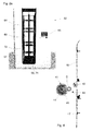
- FIG. 1a shows a first embodiment of a guide device 1 with a hydraulic counterbalance assembly 2.
- the two guided in pendulum operation tool units 3, 4 are operatively connected to each other via hydraulic means.
- the weight equalization takes place via a hydraulic fluid 7 moved in a hydraulic line, wherein the hydraulic fluid is lifted at one end together with the first tool unit 3 in the hydraulic line and lowered at another end with the second tool unit 4 in the hydraulic line and vice versa.
- a second tool unit 4 may also be provided a counterweight.
- the weight compensation arrangement can also be designed pneumatically, wherein the hydraulic fluid is replaced by a gas.
- the hydraulic fluid is replaced by a gas.
- preference is given to a hydraulic solution.
- FIG. 1b shows a second embodiment of a guide device 11 with a, comprising a belt or chain 17 weight compensation assembly 12.
- the device comprises a tool unit 13 and a counterweight 14.
- Tool unit 13 and counterweight 14 are connected by a belt or via a chain 17 with each other mechanically connected.
- the belt or the chain 17 is guided over deflection rollers 15, wherein on a first side of the guide rollers 15, the tool unit 13 and on the other side of the guide rollers 15, the counterweight 14 is arranged.
- the belt or the chain 17 can now be driven via a drive 16 in two opposite directions.
- tool unit 13 and counterweight 14 can be raised and lowered alternately in a pendulum operation.
- the tool unit 13 is designed to be rotatable about a rotation axis D according to this embodiment and includes three arranged around the rotation axis D around different processing tools 13a, 13b, 13c. By rotating the tool unit 13 about the rotation axis D, the processing tools 13a, 13b, 13c can be individually guided into a working position. As a result, with a tool unit 13, a plurality of processing steps can be carried out on the snow sports device without the machining position of the snow sports device having to be changed for this purpose.
- a single machining tool can be provided.
- a second tool unit can also be provided.
- Figure 1c shows a third embodiment of a guide device 21 with a, comprising a belt or chain 27 weight compensation assembly 22.
- the device comprises a first and second tool unit 23, 24.
- the two tool units 23, 24 are via a belt or via a chain 27 mechanically connected to each other.
- the belt or chain 27 is guided over deflection rollers 15, the first tool unit 23 being arranged on a first side of the deflection rollers 25 and the second tool unit 24 being arranged on the other side of the deflection rollers 25.
- the belt or chain 27 can now be driven via a drive 26 in two opposite directions. This allows the two tool units 23, 24 are alternately raised and lowered in a pendulum operation.
- the tool units 23, 24 each contain a single machining tool.
- the tool units 23, 24 can also be designed such that they can rotate about an axis of rotation D and contain a plurality of different machining tools arranged around the axis of rotation D.
- Figure 1d shows a fourth embodiment of a guide device 31 with a rocker 37 containing weight compensation assembly 32.
- the device comprises a first and second tool unit 33, 34.
- the two tool units 33, 34 are mechanically connected to each other via the rocker 37.
- the rocker 37 is pivotally mounted via a bearing 35 arranged between the two tools 33, 34. Furthermore, the rocker 37 is supported on a support means 39 via the bearing 35.
- the rocker 37 can now be offset by a drive 36 in a rocking motion.
- the rocking motion represents an up-and-down movement, in which the two tool units 33, 34 are alternately raised and lowered.
- the tool units 33, 34 each contain a single machining tool.
- the tool units 33, 34 can also be designed such that they can rotate about an axis of rotation D and contain a plurality of different machining tools arranged around the axis of rotation D.
- a counterweight may also be provided instead of a second tool unit.
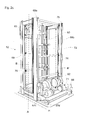
- FIG. 2a shows a preferred embodiment of a processing device according to the invention 52.
- the processing device 52 includes one in connection with the FIG. 2b Retaining tree 60 described in more detail, which is arranged centrally in a processing space 72.
- the processing space 72 is bounded by a device housing 57.
- the device housing 57 includes a supply port 58 through which the snow sport devices 64 are inserted into the processing space 72.
- the feed opening 58 can be closed by a door 74 in the device housing 57.
- the control panel 65 of an operating device is further arranged.
- the processing device 52 can be controlled accordingly via the operating device.
- FIG. 2b shows the processing device 52 after FIG. 2a but without device housing.
- the already mentioned holding tree 60 is in a central region of the processing space 72 and is rotatably supported about a vertical axis A. This allows the snow-sport devices 64 to pivot between various processing positions arranged around the holding beam 60 or between a feed or removal position likewise arranged around the holding beam 60 and a processing position.
- the feed or removal position is assigned to a feed or removal side.
- the holding tree 60 takes on each of two opposite sides of a respective snow sports device 64. Accordingly, the holding tree 60 on both sides of each holding means for holding the snow sports equipment, such as. As grippers or vacuum elements, on.
- the snow sports equipment 64 are held by the holding tree 60 with their treads 70 directed outwards. That the treads 70 are directed toward the tool units 62, 63 described below.
- the processing device 52 further includes two tool units 62, 63 arranged opposite one another and guided by a common guide device 71.
- the holding beam 60 is arranged between the two tool units.
- the guide device 71 includes a weight compensation arrangement 75 with a chain or belt guide according to the in Figure 1c described principle.
- the two tool units 62, 63 are each guided along two spaced apart, parallel guide profiles 76 and also over two spaced, parallel guided belts or chains 68a, 68b mechanically connected to each other.
- the mentioned guide profile pairs 76 of the two tool units 62, 63 are opposite each other.
- the guide profiles define a machining path B, B 'along which the tool units 62, 63 are moved up and down.
- the guide profiles 76 are part of a mounting frame 69. Such an arrangement ensures a uniform lifting and lowering of the tool units 62, 63 between the two guide profiles 76th
- the machining sections B, B 'of the two tool units 62, 63 preferably run parallel to one another. However, they can also be at an angle to each other.
- the two chains or belts 68a, 68b are arranged on both sides in the region of the guide profiles 76.
- the chains or belts 68a, 68b are endless.
- the belts or chains 68a, 68b are guided over deflection rollers 67a-e.
- the two tool units 62, 63 are each laterally connected to the two belts or the chains 68a, 68b, wherein between two tool units 62, 63 at least one deflection roller 67a, 67e is arranged, which controls the movement of the belt or chain 68a, 68b deflect accordingly between the two tool units 62, 63.
- the belts or chains 68a, 68b are driven by a drive 66.
- the two tool units 62, 63 are alternately raised and lowered to execute the processing steps in shuttle operation along the processing line B, B '.
- the two tool units 62, 63 each contain different processing tools, which perform different processing steps.
- the snow sports equipment 64 are moved to the supply and removal side. That is, the supply and Weg211seite is located laterally of the tool units 62, 63 in the region of the supply and WegScienceö réelle 58th
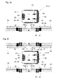
- FIGS. 3a to 3f illustrated embodiments of systems 51.1, 51.2, 51.3, 51.4, 51.5, 51.6 with differently arranged feed and Wegzhouvoriquesen all include a processing device 52 as for example in the FIGS. 2a and 2 B is described.
- the processing device can also be designed differently. Rather, in the foreground of the present embodiments is the feeding and removal device and the type of supply and removal of the snow sports equipment.
- the in the FIGS. 3a to 3f Processing device 52 shown has a processing space 72 enclosed by a device housing 57.
- a rotatably mounted holding tree 60 is arranged, on which the snow sports equipment 61, 64 are supported for carrying out the various processing steps.
- tool units 62, 63 are provided on both sides of the holding tree 60 .
- the tool units 62, 63 are guided via a guide device in pendulum mode.
- the processing device 52 is on the FIGS. 2a and 2 B as well as the corresponding description.
- the processing device 52 includes at least one feed side to which a feed opening 58 is provided in the device housing 57.
- the feed opening 58 is z. B. via a door in the device housing 57 closable.
- the feed opening 58 is viewed in the direction of rotation of the holding tree 60 between the tool units 62, 63 arranged.
- the systems 51.1, 51.2, 51.3, 51.4, 51.5, 51.6 also each contain at least one feeding device 53, via which the snow sports equipment, such as snowboards 61 or skis 64, are fed to the processing device 52.
- the feeding device 53 comprises a device frame for receiving the snow sports equipment 61, 64.
- the snow sports equipment 61, 64 are supplied in a relative to their longitudinal axis with respect to a horizontal inclined to vertical orientation of the processing device 52. That the snow sports equipment 61, 64 are substantially upright in the feeder 53.
- the feeding device 53 further includes a holding and conveying device 73 integrated in the device rack for holding the snow sports equipment 61, 64 next to each other and for laterally conveying the snow sports equipment 61, 64 along a feeding direction Z to the feeding side of the processing device 52.
- the feed direction Z is horizontal or substantially horizontal.
- the running surfaces of the snow sports equipment 61, 64 are aligned in the holding and conveying device 73 of the feeding device 53 to a common side.
- the running surfaces of the snow sports equipment 61, 64 are aligned according to present embodiments of the support and conveyor 73 out. In this way, the snow sports equipment 61, 64 for the transfer in the Machining device 52 are detected by corresponding detection means on that of the tread opposite side.
- the feeding device 53 conveys the snow sports equipment 61, 64 in a lateral conveying movement to the feed side of the processing device 52.
- a transfer device 55 is arranged between the feeding device 53 and the feed opening 58 of the processing device 52.
- the transfer device 55 is for transferring the snow sports equipment 61, 64 from the feeding device 53 into the processing space 72 of the processing device 52 in a transfer direction TZ.
- the transfer direction TZ runs horizontally or substantially horizontally, wherein vertical or essentially vertical lifting movements as well as tilting movements of the snow sports equipment during the transfer are conceivable.
- the feed device 53 and the transfer device 55 and the processing device 52 are designed and arranged such that the snow sport devices 61, 64 are transferred into the processing device 52 in a transfer direction TZ that is perpendicular or substantially perpendicular to the feed direction Z.
- Annex 51.1 according to FIG. 3a now contains only a feeder 52 of the type described. According to this embodiment, no Wegbulvoriques is provided. The snow sports equipment 61, 64 are rather taken manually here.
- inventive systems 51.2, 51.3, 51.4, 51.5, 51.6 according to the FIGS. 3b to 3f in each case at least one removal device 54, via which the snow sports equipment is led away from the processing device 52, is also contained.
- the removal device 53 comprises a device frame for receiving the snow sports equipment 61, 64.
- the snow sports equipment 61, 64 are guided away from the processing device 52 via the removal device 54 in a direction of vertical inclination with respect to their horizontal axis relative to a horizontal. That the snow sports equipment 61, 64 are substantially upright in the removal device 54.
- the removal device 54 also includes an integrated into the device rack mounting and conveying device 73 for supporting the snow sports equipment 61, 64 side by side and for laterally conveying the snow sports equipment 61, 64 along a Wegnaturalcardi W away from the Weglimseite the processing device 52.
- the removal direction W is horizontal or substantially horizontal.
- the running surfaces of the snow sports equipment 61, 64 are aligned in the holding and conveying device 73 of the removal device 54 to a common side.
- the running surfaces of the snow sports equipment 61, 64 are aligned according to present embodiments of the support and conveyor 73 out. In this way, the snow sports equipment 61, 64 can be held on the opposite side of the tread during transfer from the processing device 52 to the removal device 54 and transferred directly to the removal device 54.
- the removal device 54 conveys the snow sports equipment 61, 64 away from the removal side of the processing device 52 in a lateral conveying movement. Between the removal device 54 and a removal opening 59 of the processing device 52, a transfer device 56 is arranged. The transfer device 56 is used to transfer the snow sports equipment 61, 64 53 from the processing space 72 of the processing device 52 to the removal device 54 in a transfer direction TW.
- the transfer direction TW is horizontal or substantially horizontal, with vertical or substantially vertical lifts and tilting movements of the snow sports equipment during the transfer are conceivable.
- the removal device 54 and the transfer device 56 and the processing device 52 are designed and arranged such that the snow sport devices 61, 64 are transferred from the processing device 52 to the removal device 54 in a direction of transfer TW perpendicular or substantially perpendicular to the removal direction W.
- the feed opening 58 and the removal opening 59 of the processing device 52 lie on opposite sides.
- the feed device 53 and the removal device 54 are also arranged on mutually opposite sides, wherein the processing device 52 is arranged between the supply and removal device 53, 54.
- the transfer direction TZ of the feed is rectified in accordance with the transfer direction TW of the route guidance.
- the supply and removal device 53, 54 are arranged so that the feed direction Z and the Weggarcardi W are rectified. That is, the snow sports equipment 61, 64 are fed from a first control side (from the right in this view) to a second control side led away (according to the present view to the left).
- Stellseite here means that side relative to the processing device and relative to the supply and removal directions Z, W, on which the feed or removal device is arranged.
- the transfer direction TZ of the feed is rectified in accordance with the transfer direction TW of the route guidance.
- the feeding and removing device 53, 54 are arranged so that the feeding direction W is directed opposite to the feed direction Z.
- the snow sports equipment 61, 64 are supplied from a first control side (from the right in the present view) and are led away again to the same control side (to the right according to the present approach).
- the feed opening 58 and the removal opening 59 of the processing device 52 are also located on opposite sides.
- the feed device 53 and the removal device 54 are also arranged on mutually opposite sides, wherein the processing device 52 is arranged between the supply and removal device 53, 54.
- the transfer direction TZ of the feed is rectified in accordance with the transfer direction TW of the route guidance.
- the removal device 54 has two removal directions W1, W2 lying opposite to one another.
- the removal device 54 thus corresponds to a combination of the two Wegzhouvoriquesen FIG. 3b and 3c , This arrangement allows the routing of the Snow sports equipment 61, 64 to two, opposite parking sides out, which increases accordingly the Wegnaturalkapaztician.
- the supply opening 58 and the removal opening 59 of the processing device 52 are on the same side. That is to say, the feeding and guiding are effected via the same opening in the processing device 52.
- the feeding device 53 and the removal device 54 are also arranged on the same side.
- the feed device 53 and the removal device 54 share a common transfer device 55, 56, wherein the transfer direction TZ of the feed and the transfer direction TW of the path guide are arranged correspondingly opposite to each other.
- the feed and removal device 53, 54 are arranged on opposite parking sides.
- the feed and removal device 53, 54 are further arranged in a common plane. Accordingly, the snow sports equipment 61, 64 are arranged on the feed and removal device 53, 54 in a common plane.
- the feed direction Z is therefore also rectified to the removal direction W. Feeding and removal device 53, 54 are thus arranged in a line and are separated by the arranged at the level of the processing device 52 transfer device 55, 56.
- the embodiment of Appendix 51.6 after FIG. 3f is an extension of the embodiment according to FIG. 3e ,
- the plant 51.6 here also contains on the opposite side of the processing device 53 an identical arrangement of feeding, removal and transfer device 53, 54, 55, 56 as in FIG FIG. 3e shown.
- the extension according to FIG. 3f allows to increase the processing capacity of Appendix 51.6.
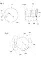
- FIG. 4 shown embodiment of a tool unit 41 according to the invention comprises three processing tools 42, 43, 44, which for different Processing steps are designed.
- processing steps can, for. For example, sanding edges, sanding surfaces or polishing surfaces.
- the tool unit 41 is rotatably supported about a rotation axis D.
- the processing tools 42, 43, 44 are arranged about the axis of rotation D.
- the tool unit 41 comprises a holder 45, which is rotatably mounted via the rotation axis D.
- the processing tools 42, 43, 44 are attached to the holder 45.
- the individual processing tools 42, 43, 44 can be pivoted into a processing position in which they are directed towards the running surface 47 of the snow sports device 46.
- the system 151 comprises a processing device 152 and a feed device 153.
- the processing device 152 has two tool units 154, 155, which are guided opposite each other in a pendulum mode, as shown, for example, in FIGS FIGS. 1c and 2a to 2c are shown.
- a second tool unit 155 may also be provided a counterweight.
- the holding device of the feeding device 153 for the snow sports equipment is circular, so that the snow sports devices are arranged in a circle around a center of the feeding device 153.
- the snow sports equipment is held up in the feeder 153.
- the holding device of the feed device 153 passes between the two tool units 154, 155 of the processing device 152.
- the feeder 152 is thus formed as a kind of feed turret.
- the processing device 152 with the tool units 154, 155 can also move along the circular holding device of the feed device 152.
- the feeder is preferably immobile.
- the processing device can also provide only a single tool unit with one or more processing tools, which is arranged outside or inside the circular holding device.
- the feeder 153 can be equipped, for example, manually with snow sports equipment.
- inventive system 251 is based on the same basic principle as the system FIG. 5 on.
- the feeding device 253 or its holding device is designed here as a feed turret.
- the feeding device 253 or its holding device is rotatably mounted about a pivot point D.
- a processing device 252 for grinding edges and / or running surfaces of the snow sports equipment is provided along the circumference of the feeder 253. Further, along the circumference of the feeder 253 is also provided a drying device 256 in which the treads are dried.
- a waxing device 255 in which the treads are grown.
- the snowsports equipment after being transferred to the feeder, is first guided by turret-like rotation of the feeder 253 to the processing apparatus 252 where the edges and / or treads are ground. Subsequently, the snow sports equipment are led to the drying station 256, where the running surfaces of the snow sports equipment are dried. Finally, the snow sports equipment is led to waxing device 255 on which the treads are grown before removal of the snow sports equipment.
- the processing spaces of the processing device 252 and the wax device 255 are separated by a space separation.
- the snow sports equipment is guided through appropriate locks in the separate processing rooms.
- the feeder 253 may be manually populated with snow sport equipment.
- Embodiments of equipment 351, 451, 551, 651 shown each comprise a processing device 352, 452, 552, 652 and a feed device 353, 453, 553, 653.
- the feeding devices 353, 453, 553, 653 have a holding device in which the snow sports devices are held upright and next to one another in a plane.
- the processing device 352, 552 each has a single tool unit 354, 554, which is arranged laterally of the feed device 353, 553.
- processing device 452, 652 has two opposing, guided in a pendulum operation tool units 454, 455; 654, 655 on, as for example in the FIGS. 1c and 2a to 2c are shown.
- a pendulum operation tool unit 454, 655 may also be provided a counterweight.
- the feeder 453, 653 is between the two tool units 454, 455; 654, 655 passed.
- the processing device 652 is guided past the snow sports equipment held in the stationary feeding device 653 for execution of processing steps.
- processing device 752 has two opposing in a pendulum operation up and down guided tool units 754, 755, as for example in the FIGS. 1c and 2a to 2c are shown.
- a second tool unit 755 may also be provided a counterweight.
- the processing tools of the tool units 754, 755 point outwards with their processing effective sides.
- the processing device 752 further includes a circulation device 753, by means of which the snow sports equipment in a circumferential direction R around the tool units 754, 755 outside guided and between the respective working positions of the tool units 754, 755 can be moved.
- the snow sports equipment is also held upright in the circulation device 753 according to this embodiment.
- the tool units 754, 755 and the circulation device 753 are arranged in a device housing 757.
- the device housing 757 includes a supply and removal opening for the automated or manual supply or removal of the snow sports equipment.
- the circulation device 753 is charged from outside with snow sports equipment, which are directed with their treads to the tool units 754, 755 out.
- the snow sports equipment are brought to processing a first processing step by means of the circulation device 753 in front of a first tool unit 754 and processed.
- the snow sports equipment are also guided by means of the circulation device 753 from the first to the second tool unit 755 and brought before this in a further processing position and then processed. After completion of all processing steps, the snow sports equipment are guided by means of the circulation device 753 to the removal opening in the device housing 757 and removed from the processing device 752.
- the circulation device 753 may, for example, have a rail guide.
- the snow sports equipment can be suspended and conveyed by means of a rail guide.
- the processing device 752 preferably also includes a pressing device, such as. B. mentioned above, which presses the snow sports equipment against the tool units.
- the apparatus 701 includes first and second series processing apparatuses 702, 703.
- the two processing apparatuses 702, 703 each include a device housing 710.
- first and second tool units 706, 707 facing each other
- third and fourth tool units 706, 707 which face each other.
- the holding tree 711 has in each case two mutually opposite holders 712, 713 for receiving a respective snow sports device 714.
- the tool units 706, 707; 708, 709 are guided by means of a weight compensation arrangement in pendulum mode.
- a processing device 702, 703, two snow sports devices 714 can be processed simultaneously.
- the two processing devices 702, 703 can in particular be constructed the same as those in the FIGS. 2a to 2c and 3a to 3f illustrated processing devices. Therefore, a detailed description of the structure and the operation of the processing device is omitted here, and instead reference is made to the aforementioned figures and the associated description of the figures.
- the plant 701 has a supply device 704 with a device rack, on which the supplied snow sports equipment 714 are held, and over which the snow sports equipment are fed semi or fully automatically.
- the snow sports devices 714 are transferred semi-automatically or fully automatically from the feed device 704 into the processing space of the first processing device 702 via a first transfer device 705 arranged on the feed side.
- Feeder 704 and transfer device 705 are not necessarily provided but can, for. B also be replaced by manual steps.
- a second transfer device 715 is arranged, via which the snow sport devices 714 can be transferred semi-automatically or fully automatically from the first to the second processing device 702, 703 after completion of the first processing steps.
- the second transfer device 715 is disposed opposite to the supply side on the discharge side.
- first processing steps such as. B. edges and surface grinding performed.
- second processing steps such as. B. Surface structure and grow carried out.
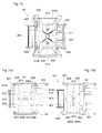
- FIGS. 10, 11a and 11b Processing apparatus 801 shown is preferably based on one of the processing apparatus according to FIGS. 2a to 2c and 3a to 3f , Therefore, a detailed description of the structure and the operation of the processing device is omitted here, and instead reference is made to the aforementioned figures and the associated description of the figures.
- the processing apparatus 801 includes a device housing 710. In the device housing 710, there are disposed first and second tool units 706, 707 facing each other.
- each a rotatable about its longitudinal axis holding tree 711 is arranged.
- the holding tree 711 has in each case two mutually opposite holders 712, 713 for receiving a respective snow sports device 714.
- the tool units 706, 707; 708, 709 are guided by means of a weight compensation arrangement in pendulum mode.
- a processing device 702 703 thus two oppositely arranged snow sports equipment 714 can be processed simultaneously.
- FIGS 10, 11a and 11b show a processing device 801 with a, about its longitudinal axis rotatable holding tree 811, which is arranged centrally in the device housing 802.
- a first and second tool unit 806, 807 are arranged, which are opposite to each other.
- the holding tree 811 is disposed between the two tool units 806, 807.
- the holding tree 811 has in each case two mutually opposite holders 812, 813 for receiving a respective snow sports device.
- the tool units 806, 807 are guided by means of a weight compensation arrangement in pendulum mode.
- a weight compensation arrangement in pendulum mode.
- the processing device is constructed - with the exception of the lock device - analogous to the processing device according to the figures. 2a, 2b, 2c and 3a to 3f built up. Therefore, a detailed description of the structure and the operation of the processing device is omitted here, and instead reference is made to the aforementioned figures and the associated description of the figures.
- the processing device 801 is characterized by a lock device in the interior of the device housing.
- the lock device divides the space in the device housing into two processing spaces 814a, 814b and an intermediate transfer space 815.
- the lock device forms for the operator to the transfer room 815 out a splash water protection and protection against moving, in particular rotating device parts.
- the lock device is designed as a rotary lock and contains a mounted on the holding tree 811 sealing body.
- the sealing body has two sealing plates 808a, 808b and rotates together with the holding tree 811 and the holders 812, 813 mounted thereon for the snow sports equipment.
- the two, opposing sealing plates 808a 808b of the sealing body are arranged offset from the holders 812, 813 along the direction of rotation by 90 °.
- Bulkheads 809 within the device housing 802 each separate the two processing spaces 814a, 814b, in which the tool units 806, 807 are located and the processing of the snow sports equipment, from the supply and removal openings 810a, 810b and the transfer room 815, in which the holding tree 811 is arranged and the takeover and delivery of snow sports equipment takes place.
- the bulkheads 809 form access openings 816, which connects the respective processing space 814 a, 814 b in the device housing 802 with the transfer space 815.
- the bulkheads 809 and sealing shields 808a, 808b are configured and arranged in the device housing 802 such that when the supports 812, 813 are in the position to receive and dispense snow sports equipment, the sealing shields 808a, 808b seal and seal the two opposing access openings abut the bulkheads.
- the holders 812, 813 with the snow sports equipment to be processed are in the processing position, they are directed through the open access opening 816 to the tool unit 806, 807 in the processing space 814a, 814b.
- the sealing plates 808a, 808b are directed in this position toward the feed or removal opening 810a, 810b. In this position as well, the sealing shields 808a, 808b can bear sealingly against the bulkhead walls 809 and thus seal the area of the supply or removal opening 810a, 810b relative to the two processing spaces 814a, 814b.
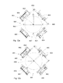
- the processing device 851 includes a holding tree 858 rotatably mounted about its longitudinal axis, centrally disposed in a device housing (not shown).
- the holding tree 858 includes four brackets 859, 860, 861, 862 disposed at an angle of 90 ° in the direction of rotation along the circumference of the support beam 858 for holding a respective snow sports equipment.
- Arranged around the holding beam 858 at an angle of 90 ° relative to one another are four tool units 852, 853, 854, 855, which each form a processing station.
- Two tool units 852, 853, 854, 855 are opposite each other.
- the tool units 852, 853, 854, 855 are each guided in a guide device, which may comprise a frame.
- the tool units 852, 853, 854, 855 are guided over a weight compensation arrangement described above.
- the guide means may also include a roller carpet as described above for supporting the snow sports equipment.
- the snow sports equipment can now be moved by a rotation of the holding tree 858 by 90 ° from one processing station to the next.
- four snow sports equipment can be processed simultaneously at a total of four processing stations.
- identical or different processing steps can be performed.
- each of the four tool units 852, 853, 854, 855 may perform another operation from the following selection: sanding edges, grinding treads, patterning treads (sanding), growing treads.
- the processing device 851 may include a supply or removal opening 856, 857 between two processing stations or tool units 852, 853, 854, 855.
- the feed or removal opening 856, 857 is z. B. arranged at an angle of 45 ° in the direction of rotation along the circumference of the holding tree 858 viewed.
- a processing device 901 includes four arranged in a device housing 909 tool units 902, 903, 904, 905. Each two tool units 902, 903 and 904, 905 are arranged side by side and are guided in a common guide device.
- the guide device comprises a guide frame and a roller carpet for supporting the snow sports equipment 910 in the working plane. Guide frame and roll carpet have been described elsewhere in the present description.
- the two juxtaposed tool units 902, 903; 904, 905 each form a common processing level.
- the processing planes of the two pairings of juxtaposed tool units 902, 903; 904, 905 are opposite each other.
- a gap 911 in particular a tunnel is formed, in which the snow sports equipment 910 and a mounting device 908 is arranged.
- a feed or removal opening 906, 907 for supplying or removing the snow sports equipment 910 is arranged.
- the two juxtaposed tool units 902, 903 are operated via a counterbalancing device in oscillation mode with the other two juxtaposed tool units 904, 905.
- the counterbalancing device has already been described elsewhere in this specification.
- each of the four tool units 902, 903, 904, 905 performs another operation from the following selection: sanding edges, grinding treads, patterning treads (sanding), growing treads.
- FIGS. 14a and 14b illustrated embodiment of a processing device 951 is designed as a wall version and contains four juxtaposed tool units 952, 953, 954, 955, which form a common processing plane.
- Two tool units 952, 953 and 954, 955 are each arranged in a common guide device 959a, 959b.
- the guide device 959a, 959b comprises a guide frame and a roller carpet for supporting the snow sports equipment 960. Guide frame and roll carpet have already been described elsewhere in the present description.
- the two tool units 952, 953 arranged in a common guide device 959a, 959b are provided with a weight compensation device in FIG Pendulum operation with the other two, also arranged in a common guide device tool units 954, 955 operated.
- the counterbalancing device has already been described elsewhere in this specification.
- each of the four tool units 952, 953, 954, 955 performs another operation from the following selection: sanding edges, grinding treads, patterning treads (sanding), growing treads.
Landscapes
- Engineering & Computer Science (AREA)
- Mechanical Engineering (AREA)
- Processing Of Stones Or Stones Resemblance Materials (AREA)
- Machine Tool Units (AREA)
Applications Claiming Priority (1)
| Application Number | Priority Date | Filing Date | Title |
|---|---|---|---|
| CH00896/12A CH706646A2 (de) | 2012-06-26 | 2012-06-26 | Anlage zur Bearbeitung von Laufflächen oder Kanten von Schneesportgeräten. |
Publications (2)
| Publication Number | Publication Date |
|---|---|
| EP2679340A2 true EP2679340A2 (fr) | 2014-01-01 |
| EP2679340A3 EP2679340A3 (fr) | 2017-11-08 |
Family
ID=48808282
Family Applications (1)
| Application Number | Title | Priority Date | Filing Date |
|---|---|---|---|
| EP13405076.4A Withdrawn EP2679340A3 (fr) | 2012-06-26 | 2013-06-25 | Installation de traitement de surfaces de roulement ou de bords d'appareils de sports d'hiver |
Country Status (2)
| Country | Link |
|---|---|
| EP (1) | EP2679340A3 (fr) |
| CH (1) | CH706646A2 (fr) |
Cited By (4)
| Publication number | Priority date | Publication date | Assignee | Title |
|---|---|---|---|---|
| WO2016161365A1 (fr) | 2015-04-01 | 2016-10-06 | Skiquiky, Llc | Dispositif et procédé de fartage d'équipements de sport de neige |
| US10589165B2 (en) | 2015-04-01 | 2020-03-17 | Skiquicky, Inc. | Snow sport equipment waxing device and method |
| DE102022125060A1 (de) * | 2022-09-28 | 2024-03-28 | Reichmann & Sohn Gmbh | Laufflächenreparaturgerät und Verfahren zur Laufflächenreparatur für Ski und Snowboard |
| DE102023109813B3 (de) | 2023-04-19 | 2024-08-29 | Marco Luck | Vorrichtung zur Bearbeitung von Ski |
Families Citing this family (1)
| Publication number | Priority date | Publication date | Assignee | Title |
|---|---|---|---|---|
| CN114367789B (zh) * | 2022-01-12 | 2022-12-30 | 中国第一汽车股份有限公司 | 一种冰面赛道竞速雪车冰刀的加工方法 |
Family Cites Families (3)
| Publication number | Priority date | Publication date | Assignee | Title |
|---|---|---|---|---|
| FR2577816A1 (fr) * | 1985-02-28 | 1986-08-29 | Skid Sa | Procede et dispositif pour le fartage de skis par pulverisation |
| DE8533909U1 (de) * | 1985-12-03 | 1986-06-12 | Jäger, Peter, 8990 Lindau | Vorrichtung zum Auftragen von Wachs auf Skier |
| DE9403293U1 (de) * | 1994-02-28 | 1994-05-05 | Volkert, Karl, 36251 Bad Hersfeld | Automat zum Schleifen von Skikanten |
-
2012
- 2012-06-26 CH CH00896/12A patent/CH706646A2/de unknown
-
2013
- 2013-06-25 EP EP13405076.4A patent/EP2679340A3/fr not_active Withdrawn
Non-Patent Citations (1)
| Title |
|---|
| None |
Cited By (5)
| Publication number | Priority date | Publication date | Assignee | Title |
|---|---|---|---|---|
| WO2016161365A1 (fr) | 2015-04-01 | 2016-10-06 | Skiquiky, Llc | Dispositif et procédé de fartage d'équipements de sport de neige |
| US10589165B2 (en) | 2015-04-01 | 2020-03-17 | Skiquicky, Inc. | Snow sport equipment waxing device and method |
| DE102022125060A1 (de) * | 2022-09-28 | 2024-03-28 | Reichmann & Sohn Gmbh | Laufflächenreparaturgerät und Verfahren zur Laufflächenreparatur für Ski und Snowboard |
| EP4344756A1 (fr) * | 2022-09-28 | 2024-04-03 | Reichmann & Sohn GmbH | Appareil de réparation de la semelle et procédé de réparation de la semelle pour ski et planche de glisse |
| DE102023109813B3 (de) | 2023-04-19 | 2024-08-29 | Marco Luck | Vorrichtung zur Bearbeitung von Ski |
Also Published As
| Publication number | Publication date |
|---|---|
| CH706646A2 (de) | 2013-12-31 |
| EP2679340A3 (fr) | 2017-11-08 |
Similar Documents
| Publication | Publication Date | Title |
|---|---|---|
| EP0477163B1 (fr) | Dispositif pour trier des découpes de plaques de verre | |
| DE3032559A1 (de) | Ortsbeweglicher bandfoerderer, insbesondere plattenbandfoerderer fuer brechanlagen | |
| DE102011103729A1 (de) | Vorrichtung zum Fördern von Gegenständen | |
| DE602004000974T2 (de) | Muldenbandförderer | |
| DE102008036949B4 (de) | Vorrichtung zum Wechseln von Bandrollen an vorzugsweisen offenen Transportbandanlagen | |
| CH706646A2 (de) | Anlage zur Bearbeitung von Laufflächen oder Kanten von Schneesportgeräten. | |
| DE2940360A1 (de) | Einzelfalzwerk | |
| EP2236745B1 (fr) | Engin d'abatage, notamment Surface Miner, ainsi que procédé de démontage et de montage d'un dispositif de transport pour engin d'abatage | |
| EP2484607B1 (fr) | Dispositif de transport et installation de transport équipée de ce dispositif | |
| EP1059223A1 (fr) | Berceaux pour le transport de pièces à travailler, en particulier de carosseries de véhicules, et dispositif de rotation pour retourner ces berceaux | |
| DE3225002A1 (de) | Raeumvorrichtung an kratzerauslegern zum abraeumen von schuettguthalden | |
| DE3416428C2 (fr) | ||
| DE20001001U1 (de) | Walzenwechselvorrichtung | |
| DE849827C (de) | Vorrichtung zum Sammeln von ausgelegten Torfsoden | |
| DE2159268C3 (de) | Vortriebsmaschine | |
| DE853890C (de) | Raupenlader mit Bohrvorrichtung | |
| DE19950892A1 (de) | Vorrichtung zur Behandlung der Oberfläche von Gegenständen | |
| DE2828233A1 (de) | Geraet zum entspeichern einer schuettguthalde | |
| DD139564A5 (de) | Anlage zur kontinuierlichen bedienung eines schuettgutlagers | |
| DE2005147B2 (de) | Entspeicherungsvorrichtung für Schüttguthalden | |
| EP3050829B1 (fr) | Convoyeur a chaine reglable en hauteur | |
| DE10349354A1 (de) | Verfahren und Anordnung zur Zustellung bzw. Entnahme von Lagergut in einen bzw. aus einem Lagerlift | |
| EP0230883B1 (fr) | Dispositif avec élévateur à godets mobile pour le stockage et le déstockage de matériaux en vrac | |
| DE202024106901U1 (de) | Einlegevorrichtung mit einer Förderbandeinheit | |
| DE202006014703U1 (de) | Schneckenfördereinrichtung sowie Übergabestation mit einer derartigen Schneckenfördereinrichtung |
Legal Events
| Date | Code | Title | Description |
|---|---|---|---|
| PUAI | Public reference made under article 153(3) epc to a published international application that has entered the european phase |
Free format text: ORIGINAL CODE: 0009012 |
|
| AK | Designated contracting states |
Kind code of ref document: A2 Designated state(s): AL AT BE BG CH CY CZ DE DK EE ES FI FR GB GR HR HU IE IS IT LI LT LU LV MC MK MT NL NO PL PT RO RS SE SI SK SM TR |
|
| AX | Request for extension of the european patent |
Extension state: BA ME |
|
| PUAL | Search report despatched |
Free format text: ORIGINAL CODE: 0009013 |
|
| AK | Designated contracting states |
Kind code of ref document: A3 Designated state(s): AL AT BE BG CH CY CZ DE DK EE ES FI FR GB GR HR HU IE IS IT LI LT LU LV MC MK MT NL NO PL PT RO RS SE SI SK SM TR |
|
| AX | Request for extension of the european patent |
Extension state: BA ME |
|
| RIC1 | Information provided on ipc code assigned before grant |
Ipc: B24B 41/06 20120101ALI20171004BHEP Ipc: B24B 7/10 20060101ALI20171004BHEP Ipc: B24B 3/00 20060101ALI20171004BHEP Ipc: B24B 27/00 20060101AFI20171004BHEP Ipc: A63C 11/06 20060101ALI20171004BHEP |
|
| STAA | Information on the status of an ep patent application or granted ep patent |
Free format text: STATUS: REQUEST FOR EXAMINATION WAS MADE |
|
| 17P | Request for examination filed |
Effective date: 20180504 |
|
| RBV | Designated contracting states (corrected) |
Designated state(s): AL AT BE BG CH CY CZ DE DK EE ES FI FR GB GR HR HU IE IS IT LI LT LU LV MC MK MT NL NO PL PT RO RS SE SI SK SM TR |
|
| STAA | Information on the status of an ep patent application or granted ep patent |
Free format text: STATUS: EXAMINATION IS IN PROGRESS |
|
| 17Q | First examination report despatched |
Effective date: 20210521 |
|
| GRAP | Despatch of communication of intention to grant a patent |
Free format text: ORIGINAL CODE: EPIDOSNIGR1 |
|
| STAA | Information on the status of an ep patent application or granted ep patent |
Free format text: STATUS: GRANT OF PATENT IS INTENDED |
|
| INTG | Intention to grant announced |
Effective date: 20220321 |
|
| STAA | Information on the status of an ep patent application or granted ep patent |
Free format text: STATUS: THE APPLICATION IS DEEMED TO BE WITHDRAWN |
|
| 18D | Application deemed to be withdrawn |
Effective date: 20220802 |