EP2679406B1 - Luftloser Reifen - Google Patents
Luftloser Reifen Download PDFInfo
- Publication number
- EP2679406B1 EP2679406B1 EP13168820.2A EP13168820A EP2679406B1 EP 2679406 B1 EP2679406 B1 EP 2679406B1 EP 13168820 A EP13168820 A EP 13168820A EP 2679406 B1 EP2679406 B1 EP 2679406B1
- Authority
- EP
- European Patent Office
- Prior art keywords
- band
- members
- airless tire
- spokes
- adjacent
- Prior art date
- Legal status (The legal status is an assumption and is not a legal conclusion. Google has not performed a legal analysis and makes no representation as to the accuracy of the status listed.)
- Not-in-force
Links
- 229920002748 Basalt fiber Polymers 0.000 claims description 15
- 230000003014 reinforcing effect Effects 0.000 claims description 14
- 239000002131 composite material Substances 0.000 claims description 7
- 229910000831 Steel Inorganic materials 0.000 claims description 6
- 239000010959 steel Substances 0.000 claims description 6
- 239000000835 fiber Substances 0.000 claims description 4
- 230000035939 shock Effects 0.000 description 7
- 238000010521 absorption reaction Methods 0.000 description 5
- 239000006185 dispersion Substances 0.000 description 5
- 230000006872 improvement Effects 0.000 description 5
- 238000004519 manufacturing process Methods 0.000 description 4
- 239000000463 material Substances 0.000 description 4
- 238000000034 method Methods 0.000 description 4
- 230000008569 process Effects 0.000 description 4
- 230000008901 benefit Effects 0.000 description 3
- 230000003068 static effect Effects 0.000 description 3
- 230000009471 action Effects 0.000 description 2
- 238000013459 approach Methods 0.000 description 2
- 230000000694 effects Effects 0.000 description 2
- 238000011156 evaluation Methods 0.000 description 2
- 239000012783 reinforcing fiber Substances 0.000 description 2
- 238000005452 bending Methods 0.000 description 1
- 238000013461 design Methods 0.000 description 1
- 238000010586 diagram Methods 0.000 description 1
- 239000013013 elastic material Substances 0.000 description 1
- 239000003365 glass fiber Substances 0.000 description 1
- 238000012986 modification Methods 0.000 description 1
- 230000004048 modification Effects 0.000 description 1
- 229920000642 polymer Polymers 0.000 description 1
- 239000011347 resin Substances 0.000 description 1
- 229920005989 resin Polymers 0.000 description 1
- 239000011435 rock Substances 0.000 description 1
- 239000007787 solid Substances 0.000 description 1
- 238000012546 transfer Methods 0.000 description 1
Images




Classifications
-
- B—PERFORMING OPERATIONS; TRANSPORTING
- B60—VEHICLES IN GENERAL
- B60C—VEHICLE TYRES; TYRE INFLATION; TYRE CHANGING; CONNECTING VALVES TO INFLATABLE ELASTIC BODIES IN GENERAL; DEVICES OR ARRANGEMENTS RELATED TO TYRES
- B60C7/00—Non-inflatable or solid tyres
- B60C7/10—Non-inflatable or solid tyres characterised by means for increasing resiliency
- B60C7/107—Non-inflatable or solid tyres characterised by means for increasing resiliency comprising lateral openings
-
- B—PERFORMING OPERATIONS; TRANSPORTING
- B60—VEHICLES IN GENERAL
- B60B—VEHICLE WHEELS; CASTORS; AXLES FOR WHEELS OR CASTORS; INCREASING WHEEL ADHESION
- B60B1/00—Spoked wheels; Spokes thereof
- B60B1/02—Wheels with wire or other tension spokes
- B60B1/04—Attaching spokes to rim or hub
-
- B—PERFORMING OPERATIONS; TRANSPORTING
- B60—VEHICLES IN GENERAL
- B60B—VEHICLE WHEELS; CASTORS; AXLES FOR WHEELS OR CASTORS; INCREASING WHEEL ADHESION
- B60B1/00—Spoked wheels; Spokes thereof
- B60B1/06—Wheels with compression spokes
-
- B—PERFORMING OPERATIONS; TRANSPORTING
- B60—VEHICLES IN GENERAL
- B60C—VEHICLE TYRES; TYRE INFLATION; TYRE CHANGING; CONNECTING VALVES TO INFLATABLE ELASTIC BODIES IN GENERAL; DEVICES OR ARRANGEMENTS RELATED TO TYRES
- B60C7/00—Non-inflatable or solid tyres
- B60C7/10—Non-inflatable or solid tyres characterised by means for increasing resiliency
- B60C7/14—Non-inflatable or solid tyres characterised by means for increasing resiliency using springs
- B60C7/16—Non-inflatable or solid tyres characterised by means for increasing resiliency using springs of helical or flat coil form
- B60C7/18—Non-inflatable or solid tyres characterised by means for increasing resiliency using springs of helical or flat coil form disposed radially relative to wheel axis
-
- B—PERFORMING OPERATIONS; TRANSPORTING
- B60—VEHICLES IN GENERAL
- B60C—VEHICLE TYRES; TYRE INFLATION; TYRE CHANGING; CONNECTING VALVES TO INFLATABLE ELASTIC BODIES IN GENERAL; DEVICES OR ARRANGEMENTS RELATED TO TYRES
- B60C7/00—Non-inflatable or solid tyres
- B60C7/10—Non-inflatable or solid tyres characterised by means for increasing resiliency
- B60C7/14—Non-inflatable or solid tyres characterised by means for increasing resiliency using springs
- B60C7/146—Non-inflatable or solid tyres characterised by means for increasing resiliency using springs extending substantially radially, e.g. like spokes
Definitions
- the present invention relates to an airless tire, and more particularly, to an airless tire which supports a load of a vehicle and of which a contact surface coming into contact with the ground is uniform and the durability of spokes are improved by the dispersion of stress for the improvement of ride quality.
- a tire is one of components of a vehicle, and comes into direct contact with the road surface. Air present in the tire further improves ride quality by absorbing shock, which is caused by the unevenness of the road surface, through a buffer action like a spring.
- Tires which can achieve the controllability of a vehicle, can be classified into a radial tire, an airless tire, a solid tire, and the like according to the structure thereof.
- a radial tire air tire type
- the radial tire has a complicated structure, and is manufactured by eight processes.
- the radial tire there is an inconvenience that air pressure absolutely important for the exhibition of performance and safety should be checked. Furthermore, the radial tire has a safety problem that a tire is damaged by an external object and shock while a vehicle is traveling.
- an airless tire is a tire of which production costs can be significantly reduced by a material and the simplification of processes and which is produced by a new process and a structure capable of reducing the amount of consumed energy and the amount of a generated harmful material. Moreover, the airless tire does not cause a problem that can occur due to the lack of air pressure or the like. In addition, the airless tire has an advantage of preventing a standing wave shape that is formed in the case of a radial tire and an advantage of significantly improving rotational resistance.
- the airless tire has a structure that is completely different from the structure of the radial tire. Further, unlike the radial tire, the airless tire does not use compressed air in design at all. Accordingly, the airless tire is free from the risk of an accident that may occur during the travel of a vehicle due to the loss or lack of air pressure. Furthermore, unlike the case of the radial tire, the production costs of the airless tire can be significantly reduced by a material and the simplification of processes.
- the airless tire includes a body that is made of an elastic material, a crown that functions as a tread and extends in a circumferential direction, and a side wall that is joined to the crown and extends.
- a non-pneumatic tire which includes a reinforced annular band supporting a load and a plurality of web spokes transmitting load forces between the annular band and a wheel or a hub while being tensioned
- Korean Patent Application Publication No. 2004-0027984 Korean Patent Application Publication No. 2004-0027984 .
- an airless tire which is adapted to perform a buffer action by a honeycomb-shaped buffer portion and to support pressure applied to the tire, also has been introduced in Korean Patent No. 1043001 .
- the present invention provides an airless tire according to claim 1 which supports a load of a vehicle and of which a contact surface coming into contact with the ground is uniform and the durability of the spoke and the absorption of shock, which is generated from a road surface and transmitted to a driver, are improved.
- An airless tire includes first and second bands that face each other with a distance interposed therebetween, a plurality of spokes that connect the first band to the second band and are provided at intervals, and first and second connecting members that connect the adjacent spokes.
- the spoke includes a first member of which one end is curved from the first band toward the second band, and a second member of which one end is curved from the second band toward the first band.
- the other ends of the first and second members are connected to each other, and the first and second members are curved in opposite directions.
- the distance between two ends of adjacent first members which are connected to the first band is longer than the distance between the other ends of the first members which are connected by the first connecting member.
- the distance between two ends of adjacent second members which are connected to the second band is longer than the distance between the other ends of the second members which are connected by the first connecting member.
- the first connecting member may be positioned at a portion where the first and second members are connected to each other and connects the adjacent spokes to form one spoke cell, and the second connecting member may be positioned between the adjacent second members to connect the adjacent spoke cells.
- the first and second connecting members may be alternately disposed.
- the airless tire may further include a tread that is connected to the outer surface of the second band, and a reinforcing layer that is positioned between the second band and the tread.
- the reinforcing layer may be one selected from a group consisting of a steel wire, a steel belt, a fiber cord, a composite, a hollow tube, and the combination thereof.
- the reinforcing layer may be one selected from a group consisting of basalt fiber, filaments based on basalt fiber, and the combination thereof.
- Each of the first and second bands may be one selected from a group consisting of basalt fiber, filaments based on basalt fiber, and the combination thereof.
- the radius (R1) of curvature of the first member may be 40 mm or more and smaller than 50 mm, and the radius (R2) of curvature of the second member may be 30 mm or more and smaller than 40 mm.
- the length of the second connecting member may be longer than the length of the first connecting member.
- the length of the second member may be longer than the length of the first member.
- the airless tire since the airless tire includes the tread, the first band, the second band, the spokes, the first connecting member, the second connecting member, and the reinforcing layer, the structural stiffness of the spokes is improved.
- a load of a vehicle is supported by the improvement of structural stiffness, a contact surface coming into contact with the ground is uniform, and the durability of spokes is improved by the dispersion of stress, particularly, the absorption of shock, which is generated from a road surface and transmitted to a driver, is improved. Therefore, it is possible to improve ride quality.
- Fig. 1 is a perspective view of the airless tire according to the embodiment of the present invention
- Fig. 2 is a front view of the airless tire shown in Fig. 1
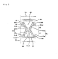
- Fig. 3 is an enlarged view of a portion A shown in Fig. 2
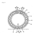
- Fig. 4 is a cross-sectional view of the airless tire taken along line IV-IV shown in Fig. 2 .
- the airless tire 1 includes a first band 40, a second band 50, a rim 20, a tread 10, a reinforcing layer 30, spokes 61, and first connecting members 62.
- the rim 20, the reinforcing layer 30, and the tread 10 may be omitted.
- Each of the first band 40 and the second band 50 has a predetermined width and is formed in the shape of a band of which both ends are connected to each other.
- the second band 50 is positioned outside the first band 40 with a distance interposed therebetween. Accordingly, the outer surface of the first band 40 faces the inner surface of the second band 50.
- Each of the first and second bands 40 and 50 may be made of one selected from a group consisting of basalt fiber, filaments based on basalt fiber, and the combination thereof.
- Basalt fiber is natural fiber extracted from basalt that is fine-grained rock made of lava flowed to the surface of the earth due to volcanism. Since basalt fiber has excellent mechanical property, basalt fiber is also used as reinforcing fiber for a polymer composite, reinforcing fiber for mending a concrete structure, or the like.
- the rim 20 which is connected to a hub drum (not shown) of a vehicle, is joined to the inner surface of the first band 40. Further, the tread 10, which controls the vehicle and comes into contact with the ground, is joined to the outer surface of the second band 50.
- the reinforcing layer 30 is positioned between the second band 50 and the tread 10.
- the reinforcing layer 30 forms an air layer in the tire and functions to support a load of the vehicle.
- the load of the vehicle is smoothly supported by the reinforcing layer 30.
- the reinforcing layer 30 may be made of one selected from a group consisting of a steel wire, a steel belt, a fiber cord, a composite, a hollow tube, and the combination thereof.
- the reinforcing layer 30 may be made of one selected from a group consisting of basalt fiber, filaments based on basalt fiber, and the combination thereof.
- a composite formed by mixing glass fiber and the like to a resin be used as the composite.
- the hollow tube has not the form of a composite but the form of a tube.
- the spokes 61 are positioned between the first and second bands 40 and 50.
- the spokes 61 function as a support so that the first band 40 is spaced apart from the second band 50.
- the spokes 61 are arranged at intervals along the first and second bands 40 and 50.
- Each of the spokes 61 includes a first member 61a and a second member 61b.
- the first member 61a protrudes from the outer surface of the first band 40 toward the second band 50.
- one end 61a1 of the first member 61a is connected to the first band 40 and the other end 61a2 thereof is spaced apart from the inner surface of the second band 50.
- the first members 61a are formed at intervals along the outer surface of the first band 40.
- the protruding first member 61a has a predetermined length and is curved.
- the first member 61a is curved so as to be opposite to an adjacent first member 61a. Accordingly, the other ends 61a2 of adjacent first members 61a face each other with a distance interposed therebetween. The distance between the other ends 61a2 of the adjacent first members 61a is shorter than the distance between one ends 61a1 thereof.
- the radius R1 of curvature of the first member be 40 mm or more and smaller than 50 mm and the radius R2 of curvature of the second member be 30 mm or more and smaller than 40 mm.
- the second member 61b is positioned on the same line as the axis of the first member 61a, and protrudes from the inner surface of the second band 50 toward the first band 40.
- the second members 61b are formed at intervals along the inner surface of the second band 50.
- One end 61b1 of the second member 61b is connected to the second band 50, and the other end 61b2 thereof is spaced apart from the outer surface of the first band 40.
- the protruding second member 61b has a predetermined length and is curved. The length of the second member 61b is longer than the length of the first member 61a.
- the second member 61b is curved so as to be opposite to the adjacent second member 61b.
- the other ends 61b2 of adjacent second members 61b face each other with a distance interposed therebetween.
- the distance between the other ends 61b2 of the adjacent second members 61b is shorter than the distance between one ends 61a1 thereof.
- the distance between one ends 61b1 of the adjacent second members 61b is longer than the distance between adjacent one ends 61a1 of the first members 61a.
- the other ends 61b2 of the second members 61b are connected to the other ends 61a2 of the first members 61a.
- the curved directions of the first and second members 61a and 61b, which are connected to each other, are opposite to each other. It is preferable that the radius R2 of curvature of the second member be 30 mm or more and smaller than 40 mm.
- Portions of the curved spokes 61 which are adjacent to the tread 10 coming into contact with the ground, may be bent while being deformed. Then, the deformed spokes 61 can be restored to the original state when the tread 10 deviates from the ground.
- the first connecting member 62 and a second connecting member 70 form one spoke cell 60 by connecting adjacent spokes 61. 22 to 26 spoke cells 60 are formed between the first and second bands 40 and 50.
- the number of the spoke cells is in the range of 22 to 26 as described above, it is advantageous in manufacturing a mold in a manufacturing process and it is possible to obtain an advantage of smoothly improving fatigue resistance and dispersing vibration.
- the number of the spoke cells is smaller than 22, there may be a problem in that the transfer of a load deteriorates due to vibration.
- the stiffness of the airless tire is increased as the number of the spoke cells exceeding 26 is increased. For this reason, there may be a problem in that the ride quality of a vehicle deteriorates.
- the first connecting member 62 is positioned between adjacent spokes 61, is positioned at a portion where the first and second members 61a and 61b are connected to each other, and connects the adjacent spokes 61.
- first connecting member 62 connecting adjacent spokes 61 and the second connecting member 70 connecting the adjacent spoke cells 60 are disposed in a zigzag pattern and connect the spokes 61 and the spoke cells 60. Since the first and second connecting members 62 and 70 are connected in a zigzag pattern, the spokes 61 can be freely deformed.
- the second connecting member 70 is positioned between adjacent spoke cells 60.
- the second connecting member 70 connects the second members 61b.
- the length of the second connecting member 70 is longer than the length of the first connecting member 62.
- the first connecting member 62 connects adjacent spokes 61 to form one spoke cell 60 and the second connecting member 70 connects adjacent spoke cells 60, so that a plurality of spaces are formed between the first and second bands 40 and 50.
- a vertical load is applied to the tread 10 when the tread 10 is perpendicular to the drum while coming into contact with the ground.
- a distance between the first and second bands 40 and 50 is reduced.
- Adjacent spokes 61, which are positioned between the first and second bands 40 and 50 between which the distance is reduced, are deformed so as to face each other while the radii of curvature thereof are reduced. Accordingly, a distance L1 is reduced. The reason for this is that a distance between portions of adjacent spokes 61 where the first and second members 61a and 61b are connected to each other is reduced due to the curved structures of the first and second members 61a and 61b.
- the first connecting member 62 is compressed while the distance L1 is reduced. Further, the first connecting member 62 may approach the second band 50. The deformed adjacent spokes 61 do not interfere with each other by the compressed first connecting member 62. Furthermore, while the distance between the adjacent spokes 61 is reduced, the distance between the portions of the adjacent spoke cells 60 corresponding to the second member 61b is increased.
- the spokes 61 which are formed of the connected first and second members 61a and 61b, are deformed in a direction where the adjacent spokes 61 approach each other, the spokes 61 are deformed in the form of the bending and stretching of an air tire. Accordingly, the control and the ride quality of a vehicle are improved.
- the airless tire 1 having this structure is deformed so that the distances between the tread 10 coming into contact with the ground and the adjacent spokes 61 are reduced.
- the adjacent spokes 61 do not interfere with each other by the first connecting member 62.
- the adjacent spoke cells 60 do not interfere with each other by the second connecting member 70. Since the adjacent spokes 61 and the spoke cells 60 do not interfere with each other, it is possible to obtain an effect of preventing the generation of noise and an effect of improving fatigue resistance.
- the deformed spoke 61 can be restored to the original state due to the elastic force thereof.
- the tire is not excessively compressed by a load generated when the drum and the tread 10 are perpendicular to each other, so that the tire can perfectly perform an original function.
- the spoke cells 60 which are formed by the connection of the curved spokes 61, are positioned between the first and second bands 40 and 50, so that the structural stiffness of the airless tire 1 according to the present invention is harmonized. Further, the spokes 61 and the spoke cells 60 are connected to each other by the first and second connecting members 62 and 70 and support the load of the vehicle, so that the contact surface of the airless tire 1 coming into contact with the ground is formed uniformly. Furthermore, since the curved spokes 61 are deformed, the durability of the spoke and the absorption of shock, which is generated from the road surface and transmitted to a driver, can be improved.
- the spoke cells 60 supporting the first and second bands 40 and 50 are positioned between the first and second bands 40 and 50 and the spokes 61 and the spoke cells 60 are connected to each other by the first and second connecting members 62 and 70. Accordingly, both a compressive force and a tensile force can be achieved by the harmonization of structural stiffness. Further, the dispersion of stress is improved by the deformation of the spokes 61. As a result, the fatigue resistance of the structure of the spokes 61 is improved.
- the static characteristic performance of the airless tire (denoted by B) having the structure of the curved spokes 61 and the curved spoke cells 60 of the present invention, which are connected to each other by the first and second connecting members 62 and 70, is improved as compared to a case where the spokes in the related art are made of an auxetic material (denoted by A).
- the airless tire (denoted by B) has a high shock absorption rate and has high resistance against a static load.
- the other ends 61a2 of the first members 61a become closer to each other as the protruding first members 61a become distant from the first band 40, and the other ends 61b2 of the second members 61b become closer to each other as the protruding second members 61b become distant from the second band 50. Accordingly, the strain of the spoke 61 is improved.
- the function as a tire can be improved without air pressure that is most important for the exhibition of the performance of an air tire. That is, since the adjacent spokes 61 do not interfere with each other, a footprint similar to the footprint of an air tire can be formed.
- the airless tire 1 according to the present invention can sufficiently support the load of the vehicle by the harmonized structural stiffness of the spokes 61. Further, since both a compressive force and a tensile force are achieved, the fatigue resistance of the structure of the spokes is improved by the improvement of the dispersion of stress. Further, the absorption performance against vibration, which is applied to a driver from the ground through a hub of the vehicle, is improved by the dispersion of vibration, so that it is possible to provide a comfortable ride quality.
- the durability of the airless tire is improved, the control performance of a vehicle is improved, and shock applied from the road surface is dispersed well, so that it is possible to expect not only the improvement of durability and but also the improvement of control performance and ride quality performance of a vehicle.
- the spoke 61 of the present invention has been formed in a curved shape in the above-mentioned description and drawings, and the shape of the spoke 61 of the present invention is not limited to this shape.
Landscapes
- Engineering & Computer Science (AREA)
- Mechanical Engineering (AREA)
- Tires In General (AREA)
Claims (10)
- Luftloser Reifen (1), umfassend:ein rundes erstes Band (40);ein zweites Band (50), das das erste Band (40) umgibt, wobei es vom ersten Band (40) beabstandet ist, und sein Durchmesser größer ist als derjenige des ersten Bandes (40);eine Anzahl Speichen (61), die das erste Band (40) mit dem zweiten Band (50) verbinden, und die zwischen dem ersten (40) und dem zweiten Band (50) angeordnet sind, und sich durch eine von außen übertragene Last zusammenziehen oder ausdehnen; underste und zweite Verbindungsbauteile (62, 70), die die nebeneinander angeordneten Speichen (61) verbinden und die eine auf die Speichen (61) ausgeübte Last verteilen,wobei die Speiche (61) ein erstes Bauteil (61 a) beinhaltet, das in einer gekrümmten Form von der ersten Bande (40) zur zweiten Bande (50) verläuft,dadurch gekennzeichnet, dass der luftlose Reifen (1) zudem ein zweites Bauteil (61 b) umfasst, das so ausgelegt ist, dass es das erste Bauteil (61 a) mit dem zweiten Band (50) verbindet, und in einer gekrümmten Form gegenüber dem ersten Bauteil (61 a) angeordnet ist,wobei der Abstand zwischen den beiden Enden der benachbarten ersten Bauteile (61 a), die mit dem ersten Band (40) verbunden sind,länger ist als der Abstand zwischen den anderen Enden der ersten Bauteile (61 a), die durch das erste Verbindungsbauteil (62) verbunden sind, und wobei der Abstand zwischen zwei Enden der benachbarten zweiten Bauteile (61 b), die mit dem zweiten Band (50) verbunden sind,länger ist als der Abstand zwischen den anderen Enden der zweiten Bauteile (61 b), die durch das erste Bauteil (62) verbunden sind.
- Luftloser Reifen (1) nach Anspruch 1,
wobei das erste Verbindungsbauteil (62) an einem Teil positioniert ist, bei dem die ersten und zweiten Bauteile (61 a, 61 b) miteinander verbunden sind, und es die benachbarten Speichen (61) verbindet, so dass eine Speichenzelle (60) entsteht und das zweite Verbindungsbauteil (70) zwischen den benachbarten zweiten Bauteilen (61 b) positioniert ist, so dass die benachbarten Speichenzellen (60) verbunden werden. - Luftloser Reifen (1) nach Anspruch 2,
wobei die ersten und zweiten Verbindungsbauteile (62, 70) in einem Zickzackmuster angeordnet sind. - Luftloser Reifen (1) nach Anspruch 1, zudem umfassend:ein Reifenprofil (10), das mit der Außenseite des zweiten Bands (50) verbunden ist; undeine Verstärkungsschicht (30), die zwischen dem zweiten Band (50) und dem Reifenprofil (10) positioniert ist.
- Luftloser Reifen (1) nach Anspruch 4,
wobei die Verstärkungsschicht (30) ausgewählt ist aus der Gruppe, bestehend aus einem Stahldraht, einem Stahlband, einer Faserschnur, einem Verbundstoff, einem Hohlröhrchen, und der Kombination davon. - Luftloser Reifen (1) nach Anspruch 5,
wobei die Verstärkungsschicht (30) ausgewählt ist aus der Gruppe, bestehend aus Basaltfaser, Filamenten auf Basaltfaser-Basis und der Kombination davon. - Luftloser Reifen (1) nach Anspruch 1,
wobei jedes der ersten und zweiten Bänder (40, 50) ausgewählt ist aus der Gruppe, bestehend aus Basaltfaser, Filamenten auf Basaltfaser-Basis und der Kombination davon. - Luftloser Reifen (1) nach Anspruch 1,
wobei der Krümmungsradius (R1) des ersten Bauteils (61 a) 40 mm oder größer und kleiner als 50 mm ist, und der Krümmungsradius (R2) des zweiten Bauteils (61 b) 30 mm oder mehr und kleiner als 40 mm ist. - Luftloser Reifen (1) nach Anspruch 1,
wobei die Länge des zweiten Verbindungsbauteils (70) länger ist als die Länge des ersten Verbindungsbauteils (62). - Luftloser Reifen (1) nach Anspruch 1,
wobei die Länge des zweiten Bauteils (61 b) länger ist als die Länge des ersten Bauteils (61 a).
Applications Claiming Priority (1)
| Application Number | Priority Date | Filing Date | Title |
|---|---|---|---|
| KR1020120069416A KR101378436B1 (ko) | 2012-06-27 | 2012-06-27 | 에어리스 타이어 |
Publications (2)
| Publication Number | Publication Date |
|---|---|
| EP2679406A1 EP2679406A1 (de) | 2014-01-01 |
| EP2679406B1 true EP2679406B1 (de) | 2015-04-01 |
Family
ID=48470795
Family Applications (1)
| Application Number | Title | Priority Date | Filing Date |
|---|---|---|---|
| EP13168820.2A Not-in-force EP2679406B1 (de) | 2012-06-27 | 2013-05-22 | Luftloser Reifen |
Country Status (5)
| Country | Link |
|---|---|
| US (1) | US9387726B2 (de) |
| EP (1) | EP2679406B1 (de) |
| JP (1) | JP5588046B2 (de) |
| KR (1) | KR101378436B1 (de) |
| CN (1) | CN103507571B (de) |
Cited By (1)
| Publication number | Priority date | Publication date | Assignee | Title |
|---|---|---|---|---|
| TWI716174B (zh) * | 2019-10-31 | 2021-01-11 | 建大工業股份有限公司 | 免充氣輪胎 |
Families Citing this family (81)
| Publication number | Priority date | Publication date | Assignee | Title |
|---|---|---|---|---|
| KR101378436B1 (ko) * | 2012-06-27 | 2014-03-27 | 한국타이어 주식회사 | 에어리스 타이어 |
| USD727837S1 (en) * | 2012-10-01 | 2015-04-28 | Compagnie Generale Des Etablissements Michelin | Pneumatic tire |
| FR2997385B1 (fr) * | 2012-10-26 | 2014-11-28 | Thales Sa | Systeme de motorisation pour articulation a pistes de roulement flexibles |
| US9242509B2 (en) * | 2013-02-07 | 2016-01-26 | Alice Chang | Non pneumatic vehicle tires and pneumatic vehicle tires with tread patterns |
| KR101356326B1 (ko) * | 2013-02-28 | 2014-01-29 | 한국타이어 주식회사 | 각선재 구조의 구조 보강물을 가지는 비공기입 타이어 |
| USD731962S1 (en) * | 2013-03-15 | 2015-06-16 | Caterpillar Inc. | Surface pattern for a tire |
| USD727247S1 (en) * | 2013-03-15 | 2015-04-21 | Caterpillar Inc. | Non-pneumatic tire |
| JP6159138B2 (ja) * | 2013-05-07 | 2017-07-05 | 住友ゴム工業株式会社 | エアレスタイヤ |
| CA2915483C (en) | 2013-06-15 | 2021-11-16 | Ronald Thompson | Annular ring and non-pneumatic tire |
| US9283806B2 (en) * | 2014-01-22 | 2016-03-15 | Lindsay Corporation | Wheel assembly for an irrigation system |
| JP6097265B2 (ja) * | 2014-10-02 | 2017-03-15 | 住友ゴム工業株式会社 | エアレスタイヤ |
| USD777655S1 (en) | 2014-12-02 | 2017-01-31 | Caterpillar Inc. | Urethane tire |
| WO2016100017A1 (en) * | 2014-12-18 | 2016-06-23 | Bridgestone Americas Tire Operations, Llc | Tire with arched spokes |
| US10899169B2 (en) | 2015-01-27 | 2021-01-26 | Mtd Products Inc | Wheel assemblies with non-pneumatic tires |
| USD792332S1 (en) | 2015-06-03 | 2017-07-18 | Mtd Products Inc | Non-pneumatic tire |
| US20160214435A1 (en) | 2015-01-27 | 2016-07-28 | Mtd Products Inc | Wheel assemblies with non-pneumatic tires |
| CN104626884B (zh) * | 2015-02-03 | 2017-03-15 | 青岛科技大学 | 一种非充气安全轮胎 |
| WO2016126983A1 (en) | 2015-02-04 | 2016-08-11 | Advancing Mobility, Llc. | Non-pneumatic tire and other annular devices |
| USD767483S1 (en) | 2015-02-13 | 2016-09-27 | Caterpillar Inc. | Tire tread |
| EP3064371B1 (de) * | 2015-03-05 | 2020-04-29 | Sumitomo Rubber Industries, Ltd. | Luftloser reifen |
| KR101714401B1 (ko) | 2015-04-13 | 2017-03-09 | 인에이블 주식회사 | 에어리스 타이어 |
| USD784917S1 (en) | 2015-06-03 | 2017-04-25 | Mtd Products Inc | Non-pneumatic tire |
| USD773387S1 (en) * | 2015-07-10 | 2016-12-06 | Caterpillar Inc. | Tire shear band |
| KR101584340B1 (ko) * | 2015-09-25 | 2016-01-13 | 주식회사 코휠 | 비공기압 바퀴 및 그 제조방법 |
| JP1556887S (de) * | 2015-10-08 | 2016-08-22 | ||
| WO2017061405A1 (ja) | 2015-10-09 | 2017-04-13 | 株式会社ブリヂストン | 非空気入りタイヤ |
| JP6577824B2 (ja) * | 2015-10-26 | 2019-09-18 | 住友ゴム工業株式会社 | エアレスタイヤ |
| US10696096B2 (en) * | 2015-12-08 | 2020-06-30 | The Goodyear Tire & Rubber Company | Non-pneumatic tire |
| WO2017106750A1 (en) | 2015-12-16 | 2017-06-22 | Thompson Ronald H | Track system for traction of a vehicle |
| US20170174005A1 (en) * | 2015-12-21 | 2017-06-22 | The Goodyear Tire & Rubber Company | Non-pneumatic tire with parabolic disks |
| KR102409373B1 (ko) | 2015-12-23 | 2022-06-15 | 삼성전자주식회사 | 로봇 청소기 |
| EP3858589B1 (de) | 2015-12-29 | 2024-01-31 | Bridgestone Americas Tire Operations, LLC | Reifen mit geformter lauffläche |
| EP3397469B1 (de) | 2015-12-29 | 2024-09-11 | Bridgestone Americas Tire Operations, LLC | Verfahren zur herstellung eines reifens mit einer verbundschicht und reifenrohling mit einer verbundschicht |
| EP3397467B1 (de) | 2015-12-29 | 2021-04-14 | Bridgestone Americas Tire Operations, LLC | Reifen mit variablem scherelement |
| USD826144S1 (en) * | 2016-06-14 | 2018-08-21 | Sumitomo Rubber Industries, Ltd. | Tire for automobile |
| US10010741B2 (en) | 2016-07-28 | 2018-07-03 | Sound Shore Innovations L.L.C. | Quiet bumper plate |
| CA173202S (en) | 2016-09-02 | 2018-02-16 | Razor Usa Llc | Airless tire |
| JP2019532859A (ja) * | 2016-09-02 | 2019-11-14 | レイザー・ユーエスエー・エルエルシー | エアレスタイヤ |
| CN109996684B (zh) * | 2016-10-03 | 2023-06-09 | 米其林集团总公司 | 用于轮胎的增强橡胶轮辐 |
| USD832770S1 (en) | 2016-10-28 | 2018-11-06 | Bridgestone Corporation | Non-pneumatic tire |
| JP1579281S (de) * | 2016-10-28 | 2017-06-19 | ||
| JP1576394S (de) * | 2016-10-28 | 2017-05-15 | ||
| US10040317B2 (en) * | 2016-11-15 | 2018-08-07 | The Goodyear Tire & Rubber Company | Non-pneumatic support structure |
| EP3339055B1 (de) * | 2016-12-21 | 2020-03-04 | Bridgestone Americas Tire Operations, LLC | Reifen mit vorgespannten speichen |
| US11235616B2 (en) * | 2016-12-22 | 2022-02-01 | Compagnie Generale Des Etablissements Michelin | Method of mounting a non-pneumatic tire onto a hub |
| CN110198847B (zh) * | 2016-12-22 | 2022-08-30 | 米其林集团总公司 | 非充气车轮和安装非充气轮胎的方法 |
| US10639226B1 (en) * | 2017-02-23 | 2020-05-05 | Koby Keyes Product Design, LLC | Mobility assistance apparatus |
| US10953695B1 (en) * | 2017-02-23 | 2021-03-23 | Koby Keyes Product Design, LLC | Light-weight walker |
| US10286725B2 (en) | 2017-03-22 | 2019-05-14 | The Goodyear Tire & Rubber Company | Non-pneumatic support structure |
| FR3067285B1 (fr) * | 2017-06-09 | 2022-01-07 | Michelin & Cie | Roue de montage pour vehicule automobile et ensemble monte comportant une telle roue de montage |
| EP3638515B1 (de) | 2017-06-15 | 2023-04-05 | Camso Inc. | Radanordnung mit einem luftlosen reifen |
| KR102005417B1 (ko) * | 2017-09-11 | 2019-07-30 | 금호타이어 주식회사 | 비공기입 타이어용 림 및 이를 포함하는 휠 |
| US20200215855A1 (en) * | 2017-10-10 | 2020-07-09 | Bridgestone Americas Tire Operations, Llc | Non-pneumatic tire with web having variable thickness |
| CA181459S (en) | 2017-11-24 | 2019-04-01 | Michelin & Cie | Pneumatic tyre |
| JP6989082B2 (ja) | 2017-12-14 | 2022-01-05 | ブリヂストン アメリカズ タイヤ オペレーションズ、 エルエルシー | マルチピースウェブを有する非空気圧式タイヤ |
| CN108382133B (zh) * | 2018-04-28 | 2023-07-18 | 无锡职业技术学院 | 一种非充气轮胎及其拆装方法 |
| CN109591518B (zh) * | 2018-12-29 | 2020-04-17 | 燕山大学 | 繁花结构式免充气轮胎 |
| WO2020142665A1 (en) * | 2019-01-04 | 2020-07-09 | Bridgestone Americas Tire Operations, Llc | Tire tread with a band layer |
| USD883913S1 (en) * | 2019-02-28 | 2020-05-12 | The Goodyear Tire & Rubber Company | Tire |
| US11273673B2 (en) | 2019-10-25 | 2022-03-15 | The Goodyear Tire & Rubber Company | Modular non-pneumatic support structure |
| US11318791B2 (en) | 2019-11-15 | 2022-05-03 | The Goodyear Tire & Rubber Company | Wheel for a support structure |
| US11142022B2 (en) | 2019-11-15 | 2021-10-12 | The Goodyear Tire & Rubber Company | Support structure |
| US11124024B2 (en) | 2019-11-25 | 2021-09-21 | The Goodyear Tire & Rubber Company | Support structure |
| CN114901493A (zh) * | 2019-12-30 | 2022-08-12 | 普利司通美国轮胎运营有限责任公司 | 具有增强支撑结构的非充气轮胎及其制造方法 |
| CN121246445A (zh) | 2020-04-24 | 2026-01-02 | 米沃奇电动工具公司 | 车轮 |
| CA199606S (en) | 2020-06-03 | 2022-06-10 | Michelin & Cie | Tire |
| KR102415200B1 (ko) * | 2020-09-01 | 2022-07-01 | 금호타이어 주식회사 | 비공기입 타이어 |
| KR102437390B1 (ko) * | 2020-11-16 | 2022-08-29 | 진성알엔디(주) | 비공기압 타이어 |
| WO2022140726A1 (en) * | 2020-12-24 | 2022-06-30 | Bridgestone Americas Tire Operations, Llc | Non-pneumatic tire with web structure |
| CN113246661B (zh) * | 2021-06-25 | 2022-04-26 | 季华实验室 | 支撑体、弹性支撑组件和轮胎 |
| USD1008161S1 (en) * | 2021-10-07 | 2023-12-19 | Hankook Tire & Technology Co., Ltd. | Non-pneumatic tire |
| KR20240077703A (ko) | 2022-11-25 | 2024-06-03 | 주식회사 지에스알 | 가변 스포크를 이용한 에어리스 타이어 |
| KR20240104583A (ko) | 2022-12-28 | 2024-07-05 | 주식회사 아이엔폴리머 | 가변스포크 에어리스 타이어의 트레드 제조용 금형 |
| KR20250070473A (ko) | 2023-11-13 | 2025-05-20 | 호남대학교 산학협력단 | 에어리스 타이어의 가변 스포크 및 휠 어셈블리 |
| KR20250074938A (ko) | 2023-11-21 | 2025-05-28 | 호남대학교 산학협력단 | 보강부재가 삽입된 에어리스 타이어의 가변스포크 어셈블리 |
| USD1115671S1 (en) | 2023-12-06 | 2026-03-03 | Compagnie Generale Des Etablissements Michelin | Tire |
| USD1095397S1 (en) | 2024-01-19 | 2025-09-30 | Compagnie Generale Des Etablissements Michelin | Tire |
| USD1119740S1 (en) * | 2024-06-27 | 2026-03-24 | Compagnie Generale Des Etablissements Michelin | Wheel |
| USD1119742S1 (en) * | 2024-06-27 | 2026-03-24 | Compagnie Generale Des Etablissements Michelin | Wheel |
| USD1119741S1 (en) * | 2024-06-27 | 2026-03-24 | Compagnie Generale Des Etablissements Michelin | Wheel |
| CN119911034B (zh) * | 2025-04-02 | 2025-08-15 | 泉州师范学院 | 一种拉胀超材料三明治厚度梯度结构的减震车轮 |
Family Cites Families (31)
| Publication number | Priority date | Publication date | Assignee | Title |
|---|---|---|---|---|
| FR2652310A1 (fr) * | 1989-09-28 | 1991-03-29 | Michelin & Cie | Bandage deformable non pneumatique. |
| KR950008368B1 (ko) * | 1992-05-07 | 1995-07-28 | 주식회사금호 | 비공기압 타이어 |
| US7108331B2 (en) * | 2000-02-28 | 2006-09-19 | Myron Stuart Hurwitz | Generation of in-line skates and skate-boards with safety “EDGING FRICTION CONTROL™” |
| US6615885B1 (en) * | 2000-10-31 | 2003-09-09 | Irobot Corporation | Resilient wheel structure |
| CA2458002C (en) | 2001-08-24 | 2010-08-17 | Michelin Recherche Et Technique S.A. | Non-pneumatic tire |
| FR2895936B1 (fr) * | 2006-01-12 | 2010-06-04 | Michelin Soc Tech | Structure porteuse pour appui de soutien et appui de soutien optimises |
| WO2007137858A2 (en) * | 2006-05-31 | 2007-12-06 | Terramark Markencreation Gmbh | Airless tire for vehicles |
| JP3923073B1 (ja) * | 2006-10-27 | 2007-05-30 | 横浜ゴム株式会社 | 非空気式タイヤ |
| US8104524B2 (en) | 2007-03-27 | 2012-01-31 | Resilient Technologies Llc | Tension-based non-pneumatic tire |
| US8109308B2 (en) * | 2007-03-27 | 2012-02-07 | Resilient Technologies LLC. | Tension-based non-pneumatic tire |
| EP2141030B1 (de) * | 2007-04-24 | 2012-02-22 | The Yokohama Rubber Co., Ltd. | Vollreifen und herstellungsverfahren dafür |
| JP2008303333A (ja) * | 2007-06-08 | 2008-12-18 | Sumitomo Rubber Ind Ltd | ゴム組成物およびそれを用いたキャップトレッドを有するタイヤ |
| EP2177375A4 (de) * | 2007-07-31 | 2013-07-17 | Toyo Tire & Rubber Co | Vollreifen und herstellungsverfahren |
| US20090173421A1 (en) * | 2008-01-08 | 2009-07-09 | Freudenberg-Nok General Partnership | Flatless Hybrid Isolated Tire |
| JP4506853B2 (ja) * | 2008-02-25 | 2010-07-21 | 横浜ゴム株式会社 | 非空気式タイヤ |
| US9108470B2 (en) * | 2008-09-29 | 2015-08-18 | Polaris Industries Inc. | Run-flat device |
| JP5221306B2 (ja) * | 2008-11-28 | 2013-06-26 | 東洋ゴム工業株式会社 | 非空気圧タイヤ |
| JP4674253B2 (ja) * | 2008-11-28 | 2011-04-20 | 東洋ゴム工業株式会社 | 非空気圧タイヤ |
| US8176957B2 (en) * | 2009-07-20 | 2012-05-15 | Resilient Technologies, Llc. | Tension-based non-pneumatic tire |
| US8944125B2 (en) * | 2009-07-20 | 2015-02-03 | Polaris Industries Inc. | Tension-based non-pneumatic tire |
| JP5314621B2 (ja) * | 2010-03-02 | 2013-10-16 | 東洋ゴム工業株式会社 | 非空気圧タイヤ |
| KR101043001B1 (ko) * | 2010-09-14 | 2011-06-21 | 한국타이어 주식회사 | 에어리스 타이어 |
| KR101301578B1 (ko) * | 2010-12-08 | 2013-08-29 | 한국타이어 주식회사 | 비공기압 타이어 |
| KR101191923B1 (ko) * | 2010-12-13 | 2012-10-17 | 한국타이어월드와이드 주식회사 | 비공기압 타이어의 스포크 설계방법 |
| US20120234444A1 (en) * | 2011-03-18 | 2012-09-20 | Chemtura Corporation | Non-pneumatic tire with annular spoke reinforcing web |
| US9573422B2 (en) * | 2012-03-15 | 2017-02-21 | Polaris Industries Inc. | Non-pneumatic tire |
| CA2864598A1 (en) * | 2012-04-05 | 2013-10-10 | Compagnie Generale Des Etablissements Michelin | Spoke for a tire with optimized thickness for improved durability |
| KR101378436B1 (ko) * | 2012-06-27 | 2014-03-27 | 한국타이어 주식회사 | 에어리스 타이어 |
| US9266388B2 (en) * | 2012-09-27 | 2016-02-23 | Mtd Products Inc | Non-pneumatic tire |
| KR101356326B1 (ko) * | 2013-02-28 | 2014-01-29 | 한국타이어 주식회사 | 각선재 구조의 구조 보강물을 가지는 비공기입 타이어 |
| KR101411103B1 (ko) * | 2013-11-06 | 2014-06-27 | 한국타이어 주식회사 | 비공기입 타이어 |
-
2012
- 2012-06-27 KR KR1020120069416A patent/KR101378436B1/ko not_active Expired - Fee Related
-
2013
- 2013-05-22 EP EP13168820.2A patent/EP2679406B1/de not_active Not-in-force
- 2013-05-24 JP JP2013109813A patent/JP5588046B2/ja not_active Expired - Fee Related
- 2013-06-19 US US13/922,218 patent/US9387726B2/en active Active
- 2013-06-27 CN CN201310262882.4A patent/CN103507571B/zh not_active Expired - Fee Related
Cited By (2)
| Publication number | Priority date | Publication date | Assignee | Title |
|---|---|---|---|---|
| TWI716174B (zh) * | 2019-10-31 | 2021-01-11 | 建大工業股份有限公司 | 免充氣輪胎 |
| US11752800B2 (en) | 2019-10-31 | 2023-09-12 | Kenda Rubber Ind. Co., Ltd. | Non-pneumatic tire |
Also Published As
| Publication number | Publication date |
|---|---|
| US20140000777A1 (en) | 2014-01-02 |
| CN103507571A (zh) | 2014-01-15 |
| JP5588046B2 (ja) | 2014-09-10 |
| EP2679406A1 (de) | 2014-01-01 |
| KR101378436B1 (ko) | 2014-03-27 |
| US9387726B2 (en) | 2016-07-12 |
| JP2014008958A (ja) | 2014-01-20 |
| CN103507571B (zh) | 2016-06-01 |
| KR20140001048A (ko) | 2014-01-06 |
Similar Documents
| Publication | Publication Date | Title |
|---|---|---|
| US9387726B2 (en) | Airless tire | |
| CN100497007C (zh) | 非充气轮胎 | |
| KR101301578B1 (ko) | 비공기압 타이어 | |
| US9333799B2 (en) | Non-pneumatic tire with reinforcing member having plate wire structure | |
| EP3393771B1 (de) | Verstärkungsstruktur für nichtpneumatisches rad | |
| US10105989B2 (en) | Shear band with interlaced reinforcements | |
| KR100967531B1 (ko) | 비공압 타이어 | |
| CN204472454U (zh) | 一种非充气轮胎 | |
| EP3647075B1 (de) | Luftloser reifen | |
| KR20160088939A (ko) | 가변 강도를 갖는 무공기 타이어 구조체 | |
| KR20120070469A (ko) | 비공기압 타이어 | |
| KR101339821B1 (ko) | 비공기입 타이어 | |
| CN104669944A (zh) | 一种非充气轮胎 | |
| JP7191133B2 (ja) | 補強構造部を含む非空気入りタイヤ | |
| JP7204716B2 (ja) | トレッド部内の構造補強部を備えた非空気入りタイヤ | |
| KR20120069988A (ko) | 비공기압 타이어 | |
| KR20230019706A (ko) | 비공기입 타이어 | |
| JP2013018427A (ja) | 非空気圧タイヤ | |
| RU2269425C2 (ru) | Непневматическая шина | |
| JP5445513B2 (ja) | 空気入りタイヤ |
Legal Events
| Date | Code | Title | Description |
|---|---|---|---|
| PUAI | Public reference made under article 153(3) epc to a published international application that has entered the european phase |
Free format text: ORIGINAL CODE: 0009012 |
|
| AK | Designated contracting states |
Kind code of ref document: A1 Designated state(s): AL AT BE BG CH CY CZ DE DK EE ES FI FR GB GR HR HU IE IS IT LI LT LU LV MC MK MT NL NO PL PT RO RS SE SI SK SM TR |
|
| AX | Request for extension of the european patent |
Extension state: BA ME |
|
| 17P | Request for examination filed |
Effective date: 20140630 |
|
| RBV | Designated contracting states (corrected) |
Designated state(s): AL AT BE BG CH CY CZ DE DK EE ES FI FR GB GR HR HU IE IS IT LI LT LU LV MC MK MT NL NO PL PT RO RS SE SI SK SM TR |
|
| RIC1 | Information provided on ipc code assigned before grant |
Ipc: B60C 7/18 20060101AFI20140814BHEP |
|
| GRAP | Despatch of communication of intention to grant a patent |
Free format text: ORIGINAL CODE: EPIDOSNIGR1 |
|
| INTG | Intention to grant announced |
Effective date: 20141024 |
|
| REG | Reference to a national code |
Ref country code: DE Ref legal event code: R079 Ref document number: 602013001349 Country of ref document: DE Free format text: PREVIOUS MAIN CLASS: B60C0007180000 Ipc: B60C0007100000 |
|
| GRAP | Despatch of communication of intention to grant a patent |
Free format text: ORIGINAL CODE: EPIDOSNIGR1 |
|
| RIC1 | Information provided on ipc code assigned before grant |
Ipc: B60C 7/10 20060101AFI20141128BHEP Ipc: B60C 7/18 20060101ALI20141128BHEP |
|
| INTG | Intention to grant announced |
Effective date: 20141217 |
|
| GRAS | Grant fee paid |
Free format text: ORIGINAL CODE: EPIDOSNIGR3 |
|
| GRAA | (expected) grant |
Free format text: ORIGINAL CODE: 0009210 |
|
| AK | Designated contracting states |
Kind code of ref document: B1 Designated state(s): AL AT BE BG CH CY CZ DE DK EE ES FI FR GB GR HR HU IE IS IT LI LT LU LV MC MK MT NL NO PL PT RO RS SE SI SK SM TR |
|
| REG | Reference to a national code |
Ref country code: GB Ref legal event code: FG4D |
|
| REG | Reference to a national code |
Ref country code: CH Ref legal event code: EP |
|
| REG | Reference to a national code |
Ref country code: IE Ref legal event code: FG4D |
|
| REG | Reference to a national code |
Ref country code: DE Ref legal event code: R096 Ref document number: 602013001349 Country of ref document: DE Effective date: 20150513 |
|
| REG | Reference to a national code |
Ref country code: AT Ref legal event code: REF Ref document number: 718843 Country of ref document: AT Kind code of ref document: T Effective date: 20150515 |
|
| REG | Reference to a national code |
Ref country code: NL Ref legal event code: VDEP Effective date: 20150401 |
|
| REG | Reference to a national code |
Ref country code: AT Ref legal event code: MK05 Ref document number: 718843 Country of ref document: AT Kind code of ref document: T Effective date: 20150401 |
|
| REG | Reference to a national code |
Ref country code: LT Ref legal event code: MG4D |
|
| PG25 | Lapsed in a contracting state [announced via postgrant information from national office to epo] |
Ref country code: NL Free format text: LAPSE BECAUSE OF FAILURE TO SUBMIT A TRANSLATION OF THE DESCRIPTION OR TO PAY THE FEE WITHIN THE PRESCRIBED TIME-LIMIT Effective date: 20150401 |
|
| PG25 | Lapsed in a contracting state [announced via postgrant information from national office to epo] |
Ref country code: LT Free format text: LAPSE BECAUSE OF FAILURE TO SUBMIT A TRANSLATION OF THE DESCRIPTION OR TO PAY THE FEE WITHIN THE PRESCRIBED TIME-LIMIT Effective date: 20150401 Ref country code: CZ Free format text: LAPSE BECAUSE OF FAILURE TO SUBMIT A TRANSLATION OF THE DESCRIPTION OR TO PAY THE FEE WITHIN THE PRESCRIBED TIME-LIMIT Effective date: 20150401 Ref country code: PT Free format text: LAPSE BECAUSE OF FAILURE TO SUBMIT A TRANSLATION OF THE DESCRIPTION OR TO PAY THE FEE WITHIN THE PRESCRIBED TIME-LIMIT Effective date: 20150803 Ref country code: FI Free format text: LAPSE BECAUSE OF FAILURE TO SUBMIT A TRANSLATION OF THE DESCRIPTION OR TO PAY THE FEE WITHIN THE PRESCRIBED TIME-LIMIT Effective date: 20150401 Ref country code: NO Free format text: LAPSE BECAUSE OF FAILURE TO SUBMIT A TRANSLATION OF THE DESCRIPTION OR TO PAY THE FEE WITHIN THE PRESCRIBED TIME-LIMIT Effective date: 20150701 Ref country code: HR Free format text: LAPSE BECAUSE OF FAILURE TO SUBMIT A TRANSLATION OF THE DESCRIPTION OR TO PAY THE FEE WITHIN THE PRESCRIBED TIME-LIMIT Effective date: 20150401 Ref country code: ES Free format text: LAPSE BECAUSE OF FAILURE TO SUBMIT A TRANSLATION OF THE DESCRIPTION OR TO PAY THE FEE WITHIN THE PRESCRIBED TIME-LIMIT Effective date: 20150401 |
|
| PG25 | Lapsed in a contracting state [announced via postgrant information from national office to epo] |
Ref country code: RS Free format text: LAPSE BECAUSE OF FAILURE TO SUBMIT A TRANSLATION OF THE DESCRIPTION OR TO PAY THE FEE WITHIN THE PRESCRIBED TIME-LIMIT Effective date: 20150401 Ref country code: IS Free format text: LAPSE BECAUSE OF FAILURE TO SUBMIT A TRANSLATION OF THE DESCRIPTION OR TO PAY THE FEE WITHIN THE PRESCRIBED TIME-LIMIT Effective date: 20150801 Ref country code: GR Free format text: LAPSE BECAUSE OF FAILURE TO SUBMIT A TRANSLATION OF THE DESCRIPTION OR TO PAY THE FEE WITHIN THE PRESCRIBED TIME-LIMIT Effective date: 20150702 Ref country code: AT Free format text: LAPSE BECAUSE OF FAILURE TO SUBMIT A TRANSLATION OF THE DESCRIPTION OR TO PAY THE FEE WITHIN THE PRESCRIBED TIME-LIMIT Effective date: 20150401 Ref country code: LV Free format text: LAPSE BECAUSE OF FAILURE TO SUBMIT A TRANSLATION OF THE DESCRIPTION OR TO PAY THE FEE WITHIN THE PRESCRIBED TIME-LIMIT Effective date: 20150401 |
|
| REG | Reference to a national code |
Ref country code: DE Ref legal event code: R097 Ref document number: 602013001349 Country of ref document: DE |
|
| PG25 | Lapsed in a contracting state [announced via postgrant information from national office to epo] |
Ref country code: EE Free format text: LAPSE BECAUSE OF FAILURE TO SUBMIT A TRANSLATION OF THE DESCRIPTION OR TO PAY THE FEE WITHIN THE PRESCRIBED TIME-LIMIT Effective date: 20150401 Ref country code: DK Free format text: LAPSE BECAUSE OF FAILURE TO SUBMIT A TRANSLATION OF THE DESCRIPTION OR TO PAY THE FEE WITHIN THE PRESCRIBED TIME-LIMIT Effective date: 20150401 Ref country code: MC Free format text: LAPSE BECAUSE OF FAILURE TO SUBMIT A TRANSLATION OF THE DESCRIPTION OR TO PAY THE FEE WITHIN THE PRESCRIBED TIME-LIMIT Effective date: 20150401 |
|
| PLBE | No opposition filed within time limit |
Free format text: ORIGINAL CODE: 0009261 |
|
| STAA | Information on the status of an ep patent application or granted ep patent |
Free format text: STATUS: NO OPPOSITION FILED WITHIN TIME LIMIT |
|
| REG | Reference to a national code |
Ref country code: IE Ref legal event code: MM4A |
|
| PG25 | Lapsed in a contracting state [announced via postgrant information from national office to epo] |
Ref country code: RO Free format text: LAPSE BECAUSE OF NON-PAYMENT OF DUE FEES Effective date: 20150401 Ref country code: SK Free format text: LAPSE BECAUSE OF FAILURE TO SUBMIT A TRANSLATION OF THE DESCRIPTION OR TO PAY THE FEE WITHIN THE PRESCRIBED TIME-LIMIT Effective date: 20150401 Ref country code: PL Free format text: LAPSE BECAUSE OF FAILURE TO SUBMIT A TRANSLATION OF THE DESCRIPTION OR TO PAY THE FEE WITHIN THE PRESCRIBED TIME-LIMIT Effective date: 20150401 |
|
| 26N | No opposition filed |
Effective date: 20160105 |
|
| REG | Reference to a national code |
Ref country code: FR Ref legal event code: PLFP Year of fee payment: 4 |
|
| PG25 | Lapsed in a contracting state [announced via postgrant information from national office to epo] |
Ref country code: IE Free format text: LAPSE BECAUSE OF NON-PAYMENT OF DUE FEES Effective date: 20150522 |
|
| PG25 | Lapsed in a contracting state [announced via postgrant information from national office to epo] |
Ref country code: SI Free format text: LAPSE BECAUSE OF FAILURE TO SUBMIT A TRANSLATION OF THE DESCRIPTION OR TO PAY THE FEE WITHIN THE PRESCRIBED TIME-LIMIT Effective date: 20150401 |
|
| PG25 | Lapsed in a contracting state [announced via postgrant information from national office to epo] |
Ref country code: BE Free format text: LAPSE BECAUSE OF FAILURE TO SUBMIT A TRANSLATION OF THE DESCRIPTION OR TO PAY THE FEE WITHIN THE PRESCRIBED TIME-LIMIT Effective date: 20150401 |
|
| PG25 | Lapsed in a contracting state [announced via postgrant information from national office to epo] |
Ref country code: MT Free format text: LAPSE BECAUSE OF FAILURE TO SUBMIT A TRANSLATION OF THE DESCRIPTION OR TO PAY THE FEE WITHIN THE PRESCRIBED TIME-LIMIT Effective date: 20150401 |
|
| REG | Reference to a national code |
Ref country code: CH Ref legal event code: PL |
|
| PG25 | Lapsed in a contracting state [announced via postgrant information from national office to epo] |
Ref country code: CH Free format text: LAPSE BECAUSE OF NON-PAYMENT OF DUE FEES Effective date: 20160531 Ref country code: LI Free format text: LAPSE BECAUSE OF NON-PAYMENT OF DUE FEES Effective date: 20160531 |
|
| REG | Reference to a national code |
Ref country code: FR Ref legal event code: PLFP Year of fee payment: 5 |
|
| PG25 | Lapsed in a contracting state [announced via postgrant information from national office to epo] |
Ref country code: BG Free format text: LAPSE BECAUSE OF FAILURE TO SUBMIT A TRANSLATION OF THE DESCRIPTION OR TO PAY THE FEE WITHIN THE PRESCRIBED TIME-LIMIT Effective date: 20150401 Ref country code: HU Free format text: LAPSE BECAUSE OF FAILURE TO SUBMIT A TRANSLATION OF THE DESCRIPTION OR TO PAY THE FEE WITHIN THE PRESCRIBED TIME-LIMIT; INVALID AB INITIO Effective date: 20130522 |
|
| PG25 | Lapsed in a contracting state [announced via postgrant information from national office to epo] |
Ref country code: CY Free format text: LAPSE BECAUSE OF FAILURE TO SUBMIT A TRANSLATION OF THE DESCRIPTION OR TO PAY THE FEE WITHIN THE PRESCRIBED TIME-LIMIT Effective date: 20150401 Ref country code: SE Free format text: LAPSE BECAUSE OF FAILURE TO SUBMIT A TRANSLATION OF THE DESCRIPTION OR TO PAY THE FEE WITHIN THE PRESCRIBED TIME-LIMIT Effective date: 20150401 |
|
| PGFP | Annual fee paid to national office [announced via postgrant information from national office to epo] |
Ref country code: GB Payment date: 20170407 Year of fee payment: 5 |
|
| PG25 | Lapsed in a contracting state [announced via postgrant information from national office to epo] |
Ref country code: TR Free format text: LAPSE BECAUSE OF FAILURE TO SUBMIT A TRANSLATION OF THE DESCRIPTION OR TO PAY THE FEE WITHIN THE PRESCRIBED TIME-LIMIT Effective date: 20150401 |
|
| PGFP | Annual fee paid to national office [announced via postgrant information from national office to epo] |
Ref country code: IT Payment date: 20170519 Year of fee payment: 5 |
|
| PG25 | Lapsed in a contracting state [announced via postgrant information from national office to epo] |
Ref country code: LU Free format text: LAPSE BECAUSE OF NON-PAYMENT OF DUE FEES Effective date: 20150522 |
|
| REG | Reference to a national code |
Ref country code: FR Ref legal event code: PLFP Year of fee payment: 6 |
|
| PG25 | Lapsed in a contracting state [announced via postgrant information from national office to epo] |
Ref country code: SM Free format text: LAPSE BECAUSE OF FAILURE TO SUBMIT A TRANSLATION OF THE DESCRIPTION OR TO PAY THE FEE WITHIN THE PRESCRIBED TIME-LIMIT Effective date: 20150401 |
|
| PG25 | Lapsed in a contracting state [announced via postgrant information from national office to epo] |
Ref country code: MK Free format text: LAPSE BECAUSE OF FAILURE TO SUBMIT A TRANSLATION OF THE DESCRIPTION OR TO PAY THE FEE WITHIN THE PRESCRIBED TIME-LIMIT Effective date: 20150401 |
|
| PG25 | Lapsed in a contracting state [announced via postgrant information from national office to epo] |
Ref country code: AL Free format text: LAPSE BECAUSE OF FAILURE TO SUBMIT A TRANSLATION OF THE DESCRIPTION OR TO PAY THE FEE WITHIN THE PRESCRIBED TIME-LIMIT Effective date: 20150401 |
|
| GBPC | Gb: european patent ceased through non-payment of renewal fee |
Effective date: 20180522 |
|
| PG25 | Lapsed in a contracting state [announced via postgrant information from national office to epo] |
Ref country code: IT Free format text: LAPSE BECAUSE OF NON-PAYMENT OF DUE FEES Effective date: 20180522 Ref country code: GB Free format text: LAPSE BECAUSE OF NON-PAYMENT OF DUE FEES Effective date: 20180522 |
|
| REG | Reference to a national code |
Ref country code: DE Ref legal event code: R082 Ref document number: 602013001349 Country of ref document: DE Representative=s name: HL KEMPNER PATENTANWAELTE, SOLICITORS (ENGLAND, DE Ref country code: DE Ref legal event code: R082 Ref document number: 602013001349 Country of ref document: DE Representative=s name: HL KEMPNER PATENTANWALT, RECHTSANWALT, SOLICIT, DE |
|
| PGFP | Annual fee paid to national office [announced via postgrant information from national office to epo] |
Ref country code: FR Payment date: 20220316 Year of fee payment: 10 |
|
| PGFP | Annual fee paid to national office [announced via postgrant information from national office to epo] |
Ref country code: DE Payment date: 20220308 Year of fee payment: 10 |
|
| REG | Reference to a national code |
Ref country code: DE Ref legal event code: R119 Ref document number: 602013001349 Country of ref document: DE |
|
| PG25 | Lapsed in a contracting state [announced via postgrant information from national office to epo] |
Ref country code: DE Free format text: LAPSE BECAUSE OF NON-PAYMENT OF DUE FEES Effective date: 20231201 |
|
| PG25 | Lapsed in a contracting state [announced via postgrant information from national office to epo] |
Ref country code: FR Free format text: LAPSE BECAUSE OF NON-PAYMENT OF DUE FEES Effective date: 20230531 |