EP2679740A1 - Paroi de séparation mobile - Google Patents
Paroi de séparation mobile Download PDFInfo
- Publication number
- EP2679740A1 EP2679740A1 EP13173127.5A EP13173127A EP2679740A1 EP 2679740 A1 EP2679740 A1 EP 2679740A1 EP 13173127 A EP13173127 A EP 13173127A EP 2679740 A1 EP2679740 A1 EP 2679740A1
- Authority
- EP
- European Patent Office
- Prior art keywords
- wall
- switching
- movable partition
- wall element
- rail
- Prior art date
- Legal status (The legal status is an assumption and is not a legal conclusion. Google has not performed a legal analysis and makes no representation as to the accuracy of the status listed.)
- Withdrawn
Links
- 238000005192 partition Methods 0.000 title claims abstract description 33
- 238000006073 displacement reaction Methods 0.000 claims description 4
- 239000011521 glass Substances 0.000 description 2
- 239000000725 suspension Substances 0.000 description 2
- 230000001960 triggered effect Effects 0.000 description 2
- 241001136792 Alle Species 0.000 description 1
- 238000009434 installation Methods 0.000 description 1
- 230000007704 transition Effects 0.000 description 1
Images





Classifications
-
- E—FIXED CONSTRUCTIONS
- E04—BUILDING
- E04B—GENERAL BUILDING CONSTRUCTIONS; WALLS, e.g. PARTITIONS; ROOFS; FLOORS; CEILINGS; INSULATION OR OTHER PROTECTION OF BUILDINGS
- E04B2/00—Walls, e.g. partitions, for buildings; Wall construction with regard to insulation; Connections specially adapted to walls
- E04B2/74—Removable non-load-bearing partitions; Partitions with a free upper edge
- E04B2/82—Removable non-load-bearing partitions; Partitions with a free upper edge characterised by the manner in which edges are connected to the building; Means therefor; Special details of easily-removable partitions as far as related to the connection with other parts of the building
- E04B2/827—Partitions constituted of sliding panels
-
- E—FIXED CONSTRUCTIONS
- E05—LOCKS; KEYS; WINDOW OR DOOR FITTINGS; SAFES
- E05D—HINGES OR SUSPENSION DEVICES FOR DOORS, WINDOWS OR WINGS
- E05D15/00—Suspension arrangements for wings
- E05D15/06—Suspension arrangements for wings for wings sliding horizontally more or less in their own plane
- E05D15/0604—Suspension arrangements for wings for wings sliding horizontally more or less in their own plane allowing an additional movement
- E05D15/0608—Suspension arrangements for wings for wings sliding horizontally more or less in their own plane allowing an additional movement caused by track lay-out
-
- E—FIXED CONSTRUCTIONS
- E05—LOCKS; KEYS; WINDOW OR DOOR FITTINGS; SAFES
- E05F—DEVICES FOR MOVING WINGS INTO OPEN OR CLOSED POSITION; CHECKS FOR WINGS; WING FITTINGS NOT OTHERWISE PROVIDED FOR, CONCERNED WITH THE FUNCTIONING OF THE WING
- E05F17/00—Special devices for shifting a plurality of wings operated simultaneously
- E05F17/002—Special devices for shifting a plurality of wings operated simultaneously for wings which lie one behind the other when closed
-
- E—FIXED CONSTRUCTIONS
- E05—LOCKS; KEYS; WINDOW OR DOOR FITTINGS; SAFES
- E05F—DEVICES FOR MOVING WINGS INTO OPEN OR CLOSED POSITION; CHECKS FOR WINGS; WING FITTINGS NOT OTHERWISE PROVIDED FOR, CONCERNED WITH THE FUNCTIONING OF THE WING
- E05F17/00—Special devices for shifting a plurality of wings operated simultaneously
- E05F2017/005—Special devices for shifting a plurality of wings operated simultaneously for sliding wings
-
- E—FIXED CONSTRUCTIONS
- E05—LOCKS; KEYS; WINDOW OR DOOR FITTINGS; SAFES
- E05Y—INDEXING SCHEME ASSOCIATED WITH SUBCLASSES E05D AND E05F, RELATING TO CONSTRUCTION ELEMENTS, ELECTRIC CONTROL, POWER SUPPLY, POWER SIGNAL OR TRANSMISSION, USER INTERFACES, MOUNTING OR COUPLING, DETAILS, ACCESSORIES, AUXILIARY OPERATIONS NOT OTHERWISE PROVIDED FOR, APPLICATION THEREOF
- E05Y2900/00—Application of doors, windows, wings or fittings thereof
- E05Y2900/10—Application of doors, windows, wings or fittings thereof for buildings or parts thereof
- E05Y2900/13—Type of wing
- E05Y2900/142—Partition walls
Definitions
- the invention relates to a movable partition wall according to the preamble of patent claim 1.
- the wall elements are movable between a first region in which they can form a closed front in a row, and a second region in which they can be stacked side by side or behind one another, in that the running rail has at least one displacement region and at least one parking region.
- the running rail has at least one branch, in which it branches into at least two running rail sections.
- a single branch is present, wherein a roller carriage of each wall element in the one rail section and the other roller carriage of each wall element is directed into the other rail section, so that there is a side by side stacked arrangement of the wall elements in the parking area.
- the roller carriages each have guide elements which predetermine a deflection of the roller carriage in the respective rail section, for example guide rollers which engage in a groove of the guide rail.
- the invention has for its object to further develop a movable partition, which has a simple structure and / or a high flexibility in terms of the arrangement of the running rail and the parking area.
- the running rail in the region of at least one branch has at least one switching element which cooperates with at least one wall element, wherein the wall element has at least one switching device which can be automatically actuated when the switching element passes.
- the switching element may preferably interact with at least one roller carriage of the wall element.
- the switching device may be arranged in or on the roller carriage of the wall element.
- the switching element which may be formed, for example, as a switching contact, can cooperate contactlessly with the switching device of the wall element, for example, be designed as a permanent magnet or electromagnet. It is also conceivable that the switching element can interact by mechanical contact with the switching device of the wall element.
- the switching device can interact with at least one guide element of the wall element, for example with a guide roller or a sliding element of a roller carriage.
- the guide element by the switching means for example, in or out of engagement with a guide rail fixed guide means, e.g. a guide groove, to be brought.
- the guide rail has a plurality of switching elements, wherein each switching element is associated with one or more branch (s) and / or one or more specific switching device (s), so that, for example, a first wall element at a first branch is directed in a first rail section, however, the subsequent wall element in a second rail section.
- the switching device may operate on the ballpoint pen principle, i. when passing a first switching element to switch the guide member from a first to a second position and when passing a second switching element from the second back to the first position, etc.
- the switching device of the roller carriage can be "programmed" that the roller carriage is rotated by 180 °, so that it interacts in its first position with one or more specific switching element (s) and in its second, by 180 ° turned Position with one or more other switching element (s).
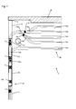
- a movable partition 1 consisting of several wall elements 2, 3 shown.
- the wall elements 2, 3 are formed in this embodiment as all-glass wings and have at the horizontal upper and lower edges of the glass sheets each have an edge profile 4, 5, which may be formed for example as a clamping profile.
- FIG. 1 closes right to the movable partition 1 a stationary building wall 9 at.
- the wall of the building 9 adjacent, left in the drawing wall element 3 is deviating from the other wall elements 2 by this left wall element 3 has a pivot fitting 6, via which it is rotatably mounted on the building wall 9.
- the upper edge profile 4 of the displaceable wall elements 2 is connected via suspension devices with roller carriage 7, the rollers roll in a mounted on the building ceiling 8 running rail 12.
- the suspension devices each have a rotary joint with a vertical axis of rotation to allow pivoting of the roller carriage 7 in curves and branches of the track rail 12.
- the lower edge profile 5 can (not shown in this drawing) Have fittings for floor guidance and / or locking of the wall elements 2 with each other and / or with respect to the building floor 10.
- FIG. 2 illustrates: The parking area 13b, in which the wall elements 2a - 2f are displaceable with open partition wall 1, in this embodiment, five mutually parallel rail sections 12a - 12e, which may be necessary to the total number of wall elements 2a - 2f of the partition 1 in the parking area 13b accommodate.
- a stationary column 11 and / or other stationary obstacles can be added, which can considerably limit the scope for the design of the transition region between the displacement area 13a and the parking area 13b.
- the first four of the building wall 9 adjacent track sections 12a - 12d can be achieved by driving around the column 11, the fifth track section 12e (and possibly further, not shown here track sections) but deviating over a branch, which already before the stationary column lies.
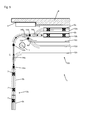
- the opening of the partition 1 is illustrated. While the partition 1 in the position according to Fig. 2 is still completely closed, was in the position according to Fig. 3 pivoted the wall element 3 in a counterclockwise direction in a niche of the building wall 9.
- the second, adjacent to the rotatable wall element 3 wall element 2a can be subsequently spent in the parking area 13b (arrow B), as shown in the Fig. 4 is shown.
- the wall element 2b first passes through a switching element 15b, which is assigned to the following branch 14b of the track rail 12.
- the switching element 15b which may be formed, for example, as a switching contact, may cooperate contactlessly with the switching device of the wall element 2a, for example as a permanent magnet or electromagnet. It is also conceivable that the switching element 15b may interact by mechanical contact with the switching device of the wall element 2a.
- the switching device here is not shown here guide element of the wall element 2b, which may be formed for example as arranged on the roller carriage 7 leadership, placed in a position that the wall element 2b is directed straight in the branch 14b.
- the guide element by the switching means for example, in or out of engagement with a guide means of the track rail 12, e.g. a guide groove, to be brought.
- a further switching element 15c is passed, which is assigned to the subsequent branch 14c of the running rail 12.
- the switching device now causes a renewed adjustment of the guide element of the wall element 2b, which causes a deflection of the wall element 2b in the branching branch of the branch 14c and the wall element 2b in the first, the building wall 9 immediately adjacent track section 12a of the parking area 13b passes.
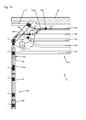
- Fig. 5 shows the sequence of movement (arrow C) of the following wall element 2b.
- the guide element of the wall element 2b is set by the switching device in each case so that the wall element 2b in all three branches 14a - 14c is directed straight and into the second rail section 12b of the parking area 13b passes, which is adjacent and parallel to the first rail section 12a.
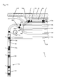
- Fig. 6 is the sequence of movements (arrow D) of the subsequent wall element 2c shown, which is also directed straight at the first branch 14a of the track rail 12, but then, by the second switching element 15b and the switching device causes, in the branching strand of the subsequent branch 14b, thereafter, effected by a further switching element 15d and the switching means, in the branching strand of another branch 14d, so that it finally enters the third rail section 12c of the parking area 13b, which is in turn aligned parallel to the first two track sections 12a, 12b.
- Fig. 5 shows in a similar manner the sequence of movements (arrow E) of the subsequent wall element 2d, which in the first two branches 14a, 14b of the track 12 still “follows" the leading wall element 2c, but then the last branch 14d, triggered by the last switching element 15d and a corresponding switching operation of the switching device of the wall element 2e, passed straight ahead and enters the fourth track section 12d of the parking area, which in turn is aligned parallel to the first three track sections 12a - 12c.
- FIG. 8 Finally, the sequence of movements (arrow direction F) of the following wall element 2e is shown, which is directed at the first branch 14a of the track rail 12, triggered by the first switching element 15a and a corresponding switching action of the switching device of the wall element 2e, in the branching branch of the branch 14a and enters the fifth rail section 12e of the parking area 13b. Further wall elements 2f can subsequently be brought into the track sections 12a-12e of the parking area 13b in a corresponding manner.
- the building wall 9 immediately adjacent branch 14e is "pointed".
- the switching element 15e associated with this branch 14e causes all the roller carriages 7 of the wall elements located in the first rail section 12a to be directed in the direction of the sliding area 13a of the track rail 12, with the exception of the then front roller carriage 7b of the first wall element 2a, which is straight ahead in FIG the rail section 12e is passed, so that finally the position according to Fig. 9 is reached.
Landscapes
- Engineering & Computer Science (AREA)
- Architecture (AREA)
- Physics & Mathematics (AREA)
- Electromagnetism (AREA)
- Civil Engineering (AREA)
- Structural Engineering (AREA)
- Mechanical Engineering (AREA)
- Power-Operated Mechanisms For Wings (AREA)
Applications Claiming Priority (1)
| Application Number | Priority Date | Filing Date | Title |
|---|---|---|---|
| DE102012211130.1A DE102012211130A1 (de) | 2012-06-28 | 2012-06-28 | Bewegliche Trennwand |
Publications (1)
| Publication Number | Publication Date |
|---|---|
| EP2679740A1 true EP2679740A1 (fr) | 2014-01-01 |
Family
ID=48745649
Family Applications (1)
| Application Number | Title | Priority Date | Filing Date |
|---|---|---|---|
| EP13173127.5A Withdrawn EP2679740A1 (fr) | 2012-06-28 | 2013-06-21 | Paroi de séparation mobile |
Country Status (2)
| Country | Link |
|---|---|
| EP (1) | EP2679740A1 (fr) |
| DE (1) | DE102012211130A1 (fr) |
Cited By (1)
| Publication number | Priority date | Publication date | Assignee | Title |
|---|---|---|---|---|
| IT201800006622A1 (it) * | 2018-06-25 | 2019-12-25 | Parete divisoria con sistema di deviazione |
Families Citing this family (1)
| Publication number | Priority date | Publication date | Assignee | Title |
|---|---|---|---|---|
| CN112647809B (zh) * | 2020-12-22 | 2022-09-13 | 安徽明坤铝业有限公司 | 一种具有防夹手结构的感应式铝合金门窗 |
Citations (5)
| Publication number | Priority date | Publication date | Assignee | Title |
|---|---|---|---|---|
| US3071825A (en) * | 1958-09-17 | 1963-01-08 | Starline | System for handling track suspended objects |
| DE19727928A1 (de) | 1997-07-01 | 1999-01-07 | Dorma Gmbh & Co Kg | An mindestens einer Laufschiene geführte Schiebewand |
| US6481359B1 (en) * | 1999-11-03 | 2002-11-19 | Modernfold, Inc. | Automatic track switching system for operable walls |
| DE20217315U1 (de) | 2002-11-07 | 2003-01-09 | Dorma Gmbh + Co. Kg, 58256 Ennepetal | Fahrschienenanordnung mit an einer Deckenschiene und an einer Bodenschiene geführtem Trennwandelement |
| DE102009038014A1 (de) * | 2009-08-20 | 2011-02-24 | Dorma Gmbh + Co. Kg | Laufschiene für eine Schiebewand und Verfahren zur Betätigung einer Weiche in einer Laufschiene |
Family Cites Families (4)
| Publication number | Priority date | Publication date | Assignee | Title |
|---|---|---|---|---|
| DE4424660C1 (de) * | 1994-07-14 | 1995-09-28 | Dorma Gmbh & Co Kg | Vorrichtung und Verfahren für den Betrieb eines automatischen Trennwandsystems |
| DE29506411U1 (de) * | 1995-04-13 | 1996-08-08 | Hüppe Form Sonnenschutz- und Raumtrennsysteme GmbH, 26133 Oldenburg | Fahrschienenanordnung für verfahrbare Trennwandelemente |
| JPH09268838A (ja) * | 1996-03-28 | 1997-10-14 | Okamura Corp | 電動間仕切装置 |
| DE19819279C1 (de) * | 1998-04-30 | 1999-03-25 | Dorma Gmbh & Co Kg | Antriebssystem für ein Trennwandsystem |
-
2012
- 2012-06-28 DE DE102012211130.1A patent/DE102012211130A1/de not_active Withdrawn
-
2013
- 2013-06-21 EP EP13173127.5A patent/EP2679740A1/fr not_active Withdrawn
Patent Citations (5)
| Publication number | Priority date | Publication date | Assignee | Title |
|---|---|---|---|---|
| US3071825A (en) * | 1958-09-17 | 1963-01-08 | Starline | System for handling track suspended objects |
| DE19727928A1 (de) | 1997-07-01 | 1999-01-07 | Dorma Gmbh & Co Kg | An mindestens einer Laufschiene geführte Schiebewand |
| US6481359B1 (en) * | 1999-11-03 | 2002-11-19 | Modernfold, Inc. | Automatic track switching system for operable walls |
| DE20217315U1 (de) | 2002-11-07 | 2003-01-09 | Dorma Gmbh + Co. Kg, 58256 Ennepetal | Fahrschienenanordnung mit an einer Deckenschiene und an einer Bodenschiene geführtem Trennwandelement |
| DE102009038014A1 (de) * | 2009-08-20 | 2011-02-24 | Dorma Gmbh + Co. Kg | Laufschiene für eine Schiebewand und Verfahren zur Betätigung einer Weiche in einer Laufschiene |
Cited By (1)
| Publication number | Priority date | Publication date | Assignee | Title |
|---|---|---|---|---|
| IT201800006622A1 (it) * | 2018-06-25 | 2019-12-25 | Parete divisoria con sistema di deviazione |
Also Published As
| Publication number | Publication date |
|---|---|
| DE102012211130A1 (de) | 2014-01-02 |
Similar Documents
| Publication | Publication Date | Title |
|---|---|---|
| DE69022643T2 (de) | In mehrere Richtungen führbare Tragwagen mit radialen Rädern für verstellbare Wandelemente. | |
| EP3555397A1 (fr) | Dispositif de déplacement avec guidage de palier à roulement | |
| EP3622149B1 (fr) | Rail de guidage d'un chariot d'une porte de meuble | |
| EP2694736B1 (fr) | Système de rails, en particulier pour un convoyeur électrique au sol | |
| EP2390413B1 (fr) | Système de rails, notamment pour une bande de palettes électrique | |
| DE2656622A1 (de) | Bewegliche abdeckung fuer energiefuehrungsleitungen, fuehrungsbahnen und sonstige einrichtungen | |
| EP3045638B1 (fr) | Système de battant coulissant et rotatif | |
| EP4048122B1 (fr) | Combinaison d'un element de mouvement et d'un element de synchronisation pour des rails de tiroir | |
| DE2659010C3 (de) | Weiche für ein Zweischienengleis für Magnetschwebefahrzeuge | |
| EP3050773A1 (fr) | Dispositif d'aiguillage doté d'un verrou disposé entre les deux contre-aiguilles | |
| EP2679740A1 (fr) | Paroi de séparation mobile | |
| EP3482026A2 (fr) | Ensemble de chariots destiné à une porte ou une fenêtre d'un bâtiment comportant en cadre fixe et un battant mobile par rapport au cadre fixe | |
| DE2919876C2 (fr) | ||
| DE102019110668A1 (de) | Schienensystem für eine Elektrobodenbahn | |
| DE102016117336B3 (de) | Lagerungs-Vorrichtung eines elastisch gelagerten Torflügels | |
| EP2884032B1 (fr) | Système de porte coulissante ou de paroi coulissante | |
| EP1002178A1 (fr) | Paroi coulissante guidee sur au moins une glissiere | |
| EP2525035A2 (fr) | Ensemble de rails de guidage pour portes coulissantes coplanaires | |
| DE708848C (de) | Beschlag fuer Schiebetueren, insbesondere rahmenlose Glasschiebetueren | |
| EP3199733B1 (fr) | Dispositif destiné à verrouiller des ouvertures d'immeubles | |
| EP2878749B1 (fr) | Porte sectionnelle dotée d'un agencement de verrouillage | |
| EP0737791A1 (fr) | Système de rails pour éléments de cloison mobiles | |
| DE102009045601B4 (de) | Bewegliche Trennwandanlage | |
| EP3327232B1 (fr) | Chariot pour élément de cloison coulissante d'une installation de paroi coulissante, élément profilé pour le guidage au plafond d'une paroi coulissante et paroi coulissante | |
| DE102012210589B4 (de) | Bewegliche Trennwand |
Legal Events
| Date | Code | Title | Description |
|---|---|---|---|
| PUAI | Public reference made under article 153(3) epc to a published international application that has entered the european phase |
Free format text: ORIGINAL CODE: 0009012 |
|
| AK | Designated contracting states |
Kind code of ref document: A1 Designated state(s): AL AT BE BG CH CY CZ DE DK EE ES FI FR GB GR HR HU IE IS IT LI LT LU LV MC MK MT NL NO PL PT RO RS SE SI SK SM TR |
|
| AX | Request for extension of the european patent |
Extension state: BA ME |
|
| 17P | Request for examination filed |
Effective date: 20140701 |
|
| RBV | Designated contracting states (corrected) |
Designated state(s): AL AT BE BG CH CY CZ DE DK EE ES FI FR GB GR HR HU IE IS IT LI LT LU LV MC MK MT NL NO PL PT RO RS SE SI SK SM TR |
|
| 17Q | First examination report despatched |
Effective date: 20160211 |
|
| STAA | Information on the status of an ep patent application or granted ep patent |
Free format text: STATUS: THE APPLICATION HAS BEEN WITHDRAWN |
|
| 18W | Application withdrawn |
Effective date: 20170804 |