EP2679866B1 - Entraînement à broche - Google Patents
Entraînement à broche Download PDFInfo
- Publication number
- EP2679866B1 EP2679866B1 EP13165382.6A EP13165382A EP2679866B1 EP 2679866 B1 EP2679866 B1 EP 2679866B1 EP 13165382 A EP13165382 A EP 13165382A EP 2679866 B1 EP2679866 B1 EP 2679866B1
- Authority
- EP
- European Patent Office
- Prior art keywords
- spindle
- channel
- channels
- channel system
- lubrication
- Prior art date
- Legal status (The legal status is an assumption and is not a legal conclusion. Google has not performed a legal analysis and makes no representation as to the accuracy of the status listed.)
- Active
Links
Images


Classifications
-
- F—MECHANICAL ENGINEERING; LIGHTING; HEATING; WEAPONS; BLASTING
- F16—ENGINEERING ELEMENTS AND UNITS; GENERAL MEASURES FOR PRODUCING AND MAINTAINING EFFECTIVE FUNCTIONING OF MACHINES OR INSTALLATIONS; THERMAL INSULATION IN GENERAL
- F16H—GEARING
- F16H25/00—Gearings comprising primarily only cams, cam-followers and screw-and-nut mechanisms
- F16H25/08—Gearings comprising primarily only cams, cam-followers and screw-and-nut mechanisms for interconverting rotary motion and reciprocating motion
- F16H25/12—Gearings comprising primarily only cams, cam-followers and screw-and-nut mechanisms for interconverting rotary motion and reciprocating motion with reciprocation along the axis of rotation, e.g. gearings with helical grooves and automatic reversal
-
- F—MECHANICAL ENGINEERING; LIGHTING; HEATING; WEAPONS; BLASTING
- F16—ENGINEERING ELEMENTS AND UNITS; GENERAL MEASURES FOR PRODUCING AND MAINTAINING EFFECTIVE FUNCTIONING OF MACHINES OR INSTALLATIONS; THERMAL INSULATION IN GENERAL
- F16H—GEARING
- F16H57/00—General details of gearing
- F16H57/04—Features relating to lubrication or cooling or heating
- F16H57/042—Guidance of lubricant
- F16H57/043—Guidance of lubricant within rotary parts, e.g. axial channels or radial openings in shafts
-
- F—MECHANICAL ENGINEERING; LIGHTING; HEATING; WEAPONS; BLASTING
- F16—ENGINEERING ELEMENTS AND UNITS; GENERAL MEASURES FOR PRODUCING AND MAINTAINING EFFECTIVE FUNCTIONING OF MACHINES OR INSTALLATIONS; THERMAL INSULATION IN GENERAL
- F16H—GEARING
- F16H57/00—General details of gearing
- F16H57/04—Features relating to lubrication or cooling or heating
- F16H57/048—Type of gearings to be lubricated, cooled or heated
- F16H57/0497—Screw mechanisms
-
- F—MECHANICAL ENGINEERING; LIGHTING; HEATING; WEAPONS; BLASTING
- F16—ENGINEERING ELEMENTS AND UNITS; GENERAL MEASURES FOR PRODUCING AND MAINTAINING EFFECTIVE FUNCTIONING OF MACHINES OR INSTALLATIONS; THERMAL INSULATION IN GENERAL
- F16H—GEARING
- F16H25/00—Gearings comprising primarily only cams, cam-followers and screw-and-nut mechanisms
- F16H25/18—Gearings comprising primarily only cams, cam-followers and screw-and-nut mechanisms for conveying or interconverting oscillating or reciprocating motions
- F16H25/20—Screw mechanisms
- F16H25/22—Screw mechanisms with balls, rollers, or similar members between the co-operating parts; Elements essential to the use of such members
- F16H25/2204—Screw mechanisms with balls, rollers, or similar members between the co-operating parts; Elements essential to the use of such members with balls
-
- Y—GENERAL TAGGING OF NEW TECHNOLOGICAL DEVELOPMENTS; GENERAL TAGGING OF CROSS-SECTIONAL TECHNOLOGIES SPANNING OVER SEVERAL SECTIONS OF THE IPC; TECHNICAL SUBJECTS COVERED BY FORMER USPC CROSS-REFERENCE ART COLLECTIONS [XRACs] AND DIGESTS
- Y10—TECHNICAL SUBJECTS COVERED BY FORMER USPC
- Y10T—TECHNICAL SUBJECTS COVERED BY FORMER US CLASSIFICATION
- Y10T74/00—Machine element or mechanism
- Y10T74/18—Mechanical movements
- Y10T74/18568—Reciprocating or oscillating to or from alternating rotary
- Y10T74/18576—Reciprocating or oscillating to or from alternating rotary including screw and nut
- Y10T74/18744—Lubrication
Definitions
- the invention relates to a spindle drive according to claim 1.
- Spindle drives are known from the prior art, which are used to convert rotating movements into linear movements or vice versa. Relubrication is difficult or impossible, particularly in the case of spindle drives that are built into compact linear actuators, without the linear actuator or the spindle drive being removed or partially dismantled. Maintenance during operation is often completely ruled out.
- the invention is based on the object of improving spindle drives known from the prior art; in particular, spindle drives that are built into linear actuators are to be improved so that simple relubrication is made possible. In particular, relubrication should be possible during ongoing operation.
- a direct screw drive lubrication with radial channels and longitudinal channels of a channel system rotating in a spindle for supplying or distributing a lubricant is known.
- the lubrication also includes a stationary channel system and a transfer space between the stationary and rotating system for supplying lubricant.
- an intermediate space designed as an annular space for the supply of lubricant is known.
- Spindle drives of embodiments have a spindle, a spindle nut interacting with the spindle, and a relubrication device.
- the relubrication device is suitable for lubricating directly between the spindle and the spindle nut, for which purpose the relubrication device has a lubrication channel outlet opening between the spindle and the spindle nut, for example in an intermediate space.
- a gap can be provided between the spindle and the spindle nut, or the spindle and the spindle nut can rest against one another or be separated only by a lubricating film of the lubricant.
- At least one lubrication channel outlet typically opens directly between the spindle and spindle nut, in particular in at least one operating state. In further embodiments, in each operating state, at least one lubrication channel outlet typically opens directly between the spindle and the spindle nut or into an intermediate space between the spindle and the spindle nut.
- rolling bodies can be provided in embodiments which reduce friction between the spindle and the spindle nut.
- rolling elements can be balls, rollers or rollers.
- Further spindle drives have a direct interaction of the spindle with the spindle nut.
- Relubrication systems of embodiments have a stationary channel system and a rotating channel system connected to the stationary channel system in order to guide lubricant to the lubricating channel outlet.
- the combination of a rotatable and a stationary channel system means that lubrication is also possible during the system.
- the term "rotatable" channel system is understood to mean that this channel system is rotated during operation or is accommodated in a part that rotates during operation, for example in a drive sleeve, or in a rotating spindle, if the embodiment is a includes rotatable spindle. Another possibility is that the rotatable channel system is arranged in the spindle nut, if this is rotated during operation in the embodiment.
- the term "stationary” preferably means that the stationary channel system is arranged in a component or in components which are not rotated during operation. Even more preferably, the stationary channel system is arranged in components which are not rotated relative to one in the housing of the spindle drive or are not moved during operation. The combination of the channel systems enables flexible lubrication.
- a transfer space is arranged between the stationary channel system and the rotatable channel system.
- the transfer space is usually at least partially concentric to the longitudinal axis of the spindle.
- the transfer space is designed in the shape of a ring, and in some embodiments the ring shape can have interruptions.
- An annular transfer space offers the advantage of a continuous application of lubricant to channels.
- An at least partially concentric transfer space enables a simple arrangement in a housing or further components of the spindle drive.
- a transfer room offers the advantage that a defined interface is created between the rotatable channel system and the stationary channel system.
- the transfer area can also be referred to as a rotary feedthrough, since at this point there is a transition from a non-rotating to a rotating system.
- the transfer space is sealed off on both sides in the axial direction by shaft sealing rings. In this way it is ensured that a largely loss-free transfer of the lubricant is possible.
- the stationary lubrication channels of the stationary channel system typically run from a stationary, external position on the spindle drive to the transfer area. Such a course can take place, for example, within housing parts or components of the housing of the spindle drive.
- the rotatable Lubrication channels of the rotatable channel system typically lead into the interior of the spindle drive and reach there moving components or components to be lubricated.
- the rotatable channel system is arranged in the spindle.
- the stationary channel system is typically arranged in a housing of the spindle drive.
- a rotatable channel system arranged in the spindle involves embodiments in which the spindle rotates during operation. With such an arrangement, lubricant can be introduced directly between the spindle and the spindle nut via the rotating spindle, with one channel or channels of the rotatable channel system in the spindle leading to the at least one lubricating channel outlet.
- the lubrication channel outlet typically opens directly between the spindle and the spindle nut, for example into the space or at the interface between the spindle and the spindle nut or directly onto the surface of the spindle outside the spindle nut.
- intermediate channels can also be provided.
- the spindle comprises a longitudinal channel and at least one radial channel connected to the longitudinal channel.
- the longitudinal channel can also be referred to as an axial channel.
- two radial channels are formed opposite one another with respect to the longitudinal axis. In this way, a more even distribution of lubricant is achieved or an imbalance is avoided.
- With the longitudinal channel it is possible to distribute lubricant over the entire engagement area of the spindle in that a plurality of radial channels adjoin the longitudinal channel at an axially spaced one another.
- at least some of the radial channels open directly or indirectly into the lubricating channel outlet.
- the spindle is non-rotatably connected to a hollow shaft rotor, the rotating channel system also running through the hollow shaft rotor.
- the hollow shaft rotor is typically used to drive the Spindle used.
- Radial channels of the rotating channel system are usually arranged in the hollow shaft rotor, but in embodiments, channels running in the axial direction can also be arranged.
- the term “radial channel” is to be understood as meaning channels which have a radial directional component.
- the radial direction component can typically be more than 50%, that is to say that the channels run at an angle of a maximum of 45 degrees relative to a radial direction of the spindle.
- the rotatable channel system is arranged in the spindle nut and comprises a radial channel.
- the invention offers the advantage that lubrication is possible, for example in the center of the spindle nut.
- a plurality of radial channels can be arranged in the spindle nut, for example two or four opposite channels that are rotated by the same angle relative to one another and lie in one plane.
- several radial channels can also be provided in several planes.
- a linear actuator with a spindle drive in one of the embodiments described above.
- Such a linear actuator offers the advantage that no dismantling of the housing, bearing, linear guide, motor encoder or sensor system is necessary for maintenance or lubrication.
- a linear actuator is a typically electromechanical drive system that converts rotation into linear movement.
- a rotor of an electric motor usually drives a spindle drive, which then performs the linear movement.
- compact linear actuators are characterized by the advantage of a significantly reduced size. This can be achieved, for example, by means of a hollow shaft rotor in which the spindle drive is integrated.
- the internal spindle drive is hardly or not at all accessible, as components such as rotor, stator, Housing, bearing, linear guide, motor encoder or sensors are usually arranged around the spindle drive so that it is no longer directly accessible.
- a grease nipple is arranged at one end of a channel of the stationary channel system in order to be able to introduce lubricant manually.
- a connection for a lubrication system is provided on the stationary channel system, so that automatic lubricant introduction is possible.
- the lubricant is introduced when the drive is at a standstill or during operation, for example when the spindle nut or spindle is rotating.
- a linear cylinder with an integrated spindle drive in accordance with one of the embodiments described here also represents an aspect of the invention.
- Another possibility in embodiments is to integrate the spindle drive into an electromechanical linear actuator.
- a hollow shaft can be provided as the drive rotor.
- Another possibility is an additional integration of a gear, for example on the drive side to drive the spindle or the spindle nut.
- a spindle drive 1 In the Fig. 1 an embodiment of a spindle drive 1 is shown.
- the spindle drive 1 has a spindle 3, which interacts with a spindle nut 7 via roller bodies 5.
- the spindle 3 In the embodiment of Fig. 1 the spindle 3 is rotatably mounted, with provision being made during operation to drive the spindle 3 in order to achieve an axial movement along the double arrows 11 on the spindle nut 7.
- a rotatable channel system is provided within the spindle 3, which channel system has a longitudinal channel 14 for lubricant along the central axis of the spindle 3.
- each lubricant is indicated by dotted lines, which is at least temporarily present in the channels during operation.
- the lubricant is generally not part of the invention.
- the longitudinal channel 14 is supplied with lubricant through first radial lubrication channels 16.
- the lubricant is conducted via the longitudinal channel 14 to second radial lubrication channels 18 which open into lubrication channel outlets 20.
- Lubricant is introduced via the lubrication channel outlets 20 into a space between the spindle 3 and the spindle nut 7, so that the rolling elements 5 or the contact of the rolling elements 5 with the spindle 3 and the spindle nut 7 are lubricated there.
- two radial lubrication channels 18 with lubrication channel outlets 20 opposite each other with respect to the axis of rotation are provided in two planes, which are axially spaced, in order to achieve lubrication over a wide area of the spindle 3.
- more or less radial lubrication channels with lubrication channel outlets can be provided.
- a rotary leadthrough with a transfer space 30 is provided, which extends annularly concentrically around the spindle in the area of the first radial lubrication channels 16. Lubricant can be applied to the first radial lubrication channels 16 via the transfer space 30.
- the lubrication channels of the rotatable channel system or the stationary channel system or both channel systems are designed with a free cross section. This means, for example, that the channels are free from material, metal or plastic or are free from material, metal or plastic arranged in the channel. This offers the advantage that lubricants can be fed along the channels unhindered without significant resistance.
- a material, metal, plastic or plastic foam is arranged at least in some of the channels in order, for example, to achieve slow distribution of the lubricant.
- a stationary lubrication channel system To supply the transfer space 30, which is sealed off by shaft seals 32, a stationary lubrication channel system is provided.
- the stationary lubrication channel system provides at least one radially arranged stationary lubrication channel 34 in a housing 40, in which the shaft seals 32 are also arranged.
- Lubricant mixtures can be introduced into the channel system via the stationary lubrication channel 34, for example via a lubrication nipple or an automatic lubrication system.
- Fig. 2 an embodiment is shown which also has a rotating spindle 3. Again, a spindle nut 7 is moved linearly along double arrows 11.
- a spindle nut 7 is moved linearly along double arrows 11.
- a drive rotor which as in the example of Fig. 2 can be designed as a hollow shaft rotor 50.
- the spindle 3 is driven and rotated with the hollow shaft rotor 50.
- the rotatable channel system is expanded to include radial rotor channels, which can be referred to as radial lubrication channels and belong to the rotatable lubrication channel system.
- the radial rotor channels directly adjoin the second radial lubrication channels 18 of the rotatable spindle 3. In this way it is achieved that a lubricant feed is possible through the hollow shaft rotor 50.
- the transfer space 30 is accordingly arranged in a concentrically ring-shaped manner around the hollow shaft rotor 50 in the area of the radial rotor channels 52.
- the hollow shaft rotor 50 is mounted within a housing 40 with bearings 60.
- a stationary lubrication channel 34 leads through the housing 40 to supply the transfer space 30.
- the transfer space 30 is designed in an annular, concentric, completely circumferential manner, with further embodiments being able to provide interruptions in the annular shape, in particular in combination with a plurality of stationary lubrication channels which can supply sections of a multipart transfer space.
- a grease nipple 62 on the outside of the housing 40 is shown schematically on the stationary lubrication channel 34. Manual lubrication is possible with the grease nipple 62.
- automatic lubrication systems and lubricants can be exchanged as required in order to achieve a supply of lubricant.
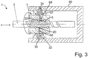
- a thrust tube 64 is shown, which is connected to the spindle nut 7 in a rigid and rotationally fixed manner. It should be noted that the thrust tube 64 with the spindle nut 7 only performs axial movements and is mounted in a rotationally fixed manner.
- a rotatable channel system is provided within the spindle nut 7 in order to supply the space between the spindle nut 7 and the spindle 3 with the rolling elements 5 with lubricant.
- Radial lubrication channels 68 are provided for this purpose.
- the expression “radial” expressly includes lubrication channels of the rotatable channel system that are inclined with respect to a radial direction, for example between 0 ° and 20 ° or 0 ° and 40 °.
- the background is that as with the one in the Fig. 3 In the radial lubrication channel 68 shown above, it may be necessary to evade next to a groove in the toothing of the spindle nut 7 in order to achieve a free lubrication channel outlet 20.
- a stationary lubrication channel 34 is arranged to supply a transfer space 30 with lubricant, which in turn supplies the radial lubrication channels 68 of the spindle nut 7 with lubricant.
- the transfer space 30 is sealed with shaft seals 32.
- the rotatable channel system comprises at least one longitudinal channel, such as in the embodiments of FIG Fig. 1 and 2 . Also the Fig. 4 shows such an embodiment with at least one longitudinal channel. In further embodiments, the rotatable channel system is free of longitudinal channels.
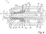
- a further embodiment is shown which differs from the embodiment of FIG Fig. 3 is extended by a hollow shaft rotor 50 as a drive rotor.
- the spindle drive 1 has further differences. So shows the rotatable Channel system longitudinal channels 14, which lead to second radial lubrication channels 18 in the spindle nut 7.
- the longitudinal channels 14 are supplied with lubricant via first radial lubrication channels 16.
- the longitudinal channel 14 leads both through the drive rotor 50 and through the spindle nut 7.
- the first radial lubrication channels 16 are located within the drive rotor 50 and could therefore also be referred to as radial rotor channels.
- FIG. 4 two longitudinal channels 14 with the associated first and second radial lubrication channels 16 and 18 are shown.
- the longitudinal channels 14 each run both through the drive rotor 50 and through the spindle nut 7.
- further longitudinal channels can be provided, for example four or six distributed over the circumference.
- the longitudinal channels 14 are supplied with lubricant through a transfer space 30 and the first radial lubrication channels 16.
- the transfer space 30 is arranged between a housing 40 and the drive rotor 50 and is sealed by shaft seals 32.
- the drive rotor 50 is mounted in the housing 40, which is rotatably connected to the spindle nut 7 and can achieve an axial movement of the spindle 3 along the double arrows 11 by rotating the spindle nut 7 via engagement with roller bodies 5.
Landscapes
- Engineering & Computer Science (AREA)
- General Engineering & Computer Science (AREA)
- Mechanical Engineering (AREA)
- Transmission Devices (AREA)
Claims (6)
- Entraînement à broche (1), en particulier pour un actionneur linéaire, comprenant- une broche (3),- un écrou de broche (7), lequel interagit avec la broche (3), et- une sortie de conduit de lubrification (20) débouchant entre la broche (3) et l'écrou de broche (7) pour la lubrification de la broche (3) et de l'écrou de broche (7),sachant que l'entraînement à broche (1) comprend en outre :- un système de conduit stationnaire,- un système de conduit rotatif relié au système de conduit stationnaire pour l'amenée de lubrifiant à la sortie de conduit de lubrification (20), sachant que le système de conduit rotatif est disposé au moins en partie dans la broche (3) ou dans un rotor d'arbre creux (50) de l'entraînement à broche (1) et comprend un conduit longitudinal (14) disposé dans la broche (3) ou dans le rotor d'arbre creux (50), au moins un conduit de lubrification radial (16) relié au conduit longitudinal (14) pour l'alimentation du conduit longitudinal (14) en lubrifiant, et des deuxièmes conduits de lubrification radiaux (18) dotés de sorties de conduit de lubrification (20), et- un compartiment de transfert (30) disposé entre le système de conduit stationnaire et le système de conduit rotatif, sachant que le compartiment de transfert (30) est constitué de manière annulaire et est étanchéifié avec des garnitures d'étanchéité d'arbre (32).
- Entraînement à broche (1) selon la revendication 1, caractérisé en ce que le compartiment de transfert (30) est constitué au moins en partie de manière concentrique par rapport à l'axe longitudinal de la broche (3).
- Entraînement à broche (1) selon la revendication 1 ou 2, caractérisé en ce que les deuxièmes conduits radiaux (18) débouchent directement dans la sortie de conduit de lubrification (20).
- Entraînement à broche (1) selon une quelconque des revendications précédentes, sachant que le système de conduit rotatif est disposé au moins en partie dans la broche (3), caractérisé en ce que la broche (3) est reliée de manière solidaire en rotation à un rotor d'arbre creux (50), sachant que le système de conduit rotatif passe aussi par le rotor d'arbre creux (50).
- Entraînement à broche (1) selon une quelconque des revendications précédentes, caractérisé en ce que des corps de roulement (5) sont disposés entre la broche (3) et l'écrou de broche (7).
- Actionneur linéaire comportant un entraînement à broche (1) selon une quelconque des revendications précédentes.
Applications Claiming Priority (1)
| Application Number | Priority Date | Filing Date | Title |
|---|---|---|---|
| DE102012105709.5A DE102012105709A1 (de) | 2012-06-28 | 2012-06-28 | Spindeltrieb |
Publications (2)
| Publication Number | Publication Date |
|---|---|
| EP2679866A1 EP2679866A1 (fr) | 2014-01-01 |
| EP2679866B1 true EP2679866B1 (fr) | 2021-01-27 |
Family
ID=48190235
Family Applications (1)
| Application Number | Title | Priority Date | Filing Date |
|---|---|---|---|
| EP13165382.6A Active EP2679866B1 (fr) | 2012-06-28 | 2013-04-25 | Entraînement à broche |
Country Status (3)
| Country | Link |
|---|---|
| US (1) | US9169907B2 (fr) |
| EP (1) | EP2679866B1 (fr) |
| DE (1) | DE102012105709A1 (fr) |
Families Citing this family (12)
| Publication number | Priority date | Publication date | Assignee | Title |
|---|---|---|---|---|
| US9821774B1 (en) * | 2013-03-04 | 2017-11-21 | Craig Alan Searer | Method and apparatus for jackscrew with integral drive nut grease fitting |
| WO2015127497A1 (fr) * | 2014-02-26 | 2015-09-03 | Techni Waterjet Pty Ltd | Actionneur linéaire |
| US9506553B2 (en) * | 2014-02-28 | 2016-11-29 | Deere & Company | Composite shaft with core insert |
| EA030874B1 (ru) | 2015-05-08 | 2018-10-31 | Акционерное общество "Диаконт" | Линейный электромеханический привод |
| KR102091916B1 (ko) * | 2015-06-23 | 2020-03-20 | 닛본 세이고 가부시끼가이샤 | 냉각액 배출장치, 볼나사장치 |
| DE102017214812A1 (de) * | 2017-08-24 | 2019-02-28 | Robert Bosch Gmbh | Gewindetrieb |
| CN110242716B (zh) * | 2019-05-06 | 2022-05-03 | 浙江非攻机械有限公司 | 丝杠传动装置 |
| US11105403B2 (en) * | 2019-09-05 | 2021-08-31 | Hiwin Technologies Corp. | Ball screw |
| CN113048206B (zh) * | 2019-12-26 | 2022-07-22 | 上银科技股份有限公司 | 具有监控功能的传动机构 |
| US11402011B2 (en) | 2020-01-13 | 2022-08-02 | Hiwin Technologies Corp. | Transmission mechanism with monitoring function |
| CN117927650B (zh) * | 2024-03-21 | 2024-05-28 | 成都道恒车辆技术有限公司 | 一种自润滑丝杠副 |
| JP7808885B1 (ja) * | 2024-07-17 | 2026-01-30 | 株式会社コスメック | 流体給排装置 |
Family Cites Families (18)
| Publication number | Priority date | Publication date | Assignee | Title |
|---|---|---|---|---|
| BE621270A (fr) * | 1958-09-08 | |||
| DE1273289B (fr) * | 1965-03-04 | 1973-11-15 | ||
| CH425361A (fr) * | 1965-10-26 | 1966-11-30 | Genevoise Instr Physique | Ecrou hydrostatique |
| DE3902857A1 (de) * | 1989-02-01 | 1990-08-02 | Mi Stankostroitelnoe Proizv Ob | Hydrostatischer schnecken-zahnstangentrieb |
| DE19519770C2 (de) * | 1994-05-30 | 2002-10-24 | Nsk Ltd | Kugelumlaufspindel |
| DE19549719B4 (de) * | 1994-05-30 | 2007-09-13 | Nsk Ltd. | Kugelumlaufspindel mit Ölzuführungsvorrichtung |
| US5809838A (en) * | 1995-05-30 | 1998-09-22 | Nsk Ltd. | Ball screw device with means for maintaining balance |
| DE10107706A1 (de) | 2001-02-19 | 2002-10-02 | Rexroth Star Gmbh | Drehlager mit Schmierkanalanordnung Gewindetrieb mit drehgelagerter Gewindemutter |
| JP2002340131A (ja) * | 2001-05-15 | 2002-11-27 | Nsk Ltd | ボールねじ |
| ES2266829T3 (es) * | 2002-02-05 | 2007-03-01 | Swac Electronic Gmbh | Dispositivo de accionamiento para unas pinzas portaelectrodos. |
| JP2003269569A (ja) * | 2002-03-15 | 2003-09-25 | Ntn Corp | ボールねじ |
| DE10235078B4 (de) * | 2002-07-31 | 2005-04-28 | Sew Eurodrive Gmbh & Co | Spindelmotor |
| DE102004043749A1 (de) | 2004-09-10 | 2006-03-16 | Bosch Rexroth Mechatronics Gmbh | Drehlager mit Schmiermittelübertragung |
| US7634952B2 (en) * | 2007-11-26 | 2009-12-22 | Hiwin Technologies Corp. | Rotating nut ball screw unit with lubricating arrangement |
| DE102008025072A1 (de) * | 2008-05-26 | 2009-12-10 | Sew-Eurodrive Gmbh & Co. Kg | Spindelmotor |
| DE102009005886A1 (de) * | 2009-01-23 | 2010-07-29 | Robert Bosch Gmbh | Spindelantrieb und Verfahren zum Schmieren eines Spindelantriebs |
| DE102009012432A1 (de) * | 2009-03-10 | 2010-09-16 | Robert Bosch Gmbh | Direkte Gewindetriebschmierung |
| DE102009023984B4 (de) * | 2009-06-05 | 2016-01-14 | Deckel Maho Pfronten Gmbh | Schmiervorrichtung für einen Kugelgewindetrieb |
-
2012
- 2012-06-28 DE DE102012105709.5A patent/DE102012105709A1/de not_active Withdrawn
-
2013
- 2013-04-25 EP EP13165382.6A patent/EP2679866B1/fr active Active
- 2013-06-25 US US13/926,587 patent/US9169907B2/en active Active
Non-Patent Citations (1)
| Title |
|---|
| None * |
Also Published As
| Publication number | Publication date |
|---|---|
| EP2679866A1 (fr) | 2014-01-01 |
| US20140000395A1 (en) | 2014-01-02 |
| US9169907B2 (en) | 2015-10-27 |
| DE102012105709A1 (de) | 2014-04-03 |
Similar Documents
| Publication | Publication Date | Title |
|---|---|---|
| EP2679866B1 (fr) | Entraînement à broche | |
| DE69308506T2 (de) | Gewinderollenmechanismus für ein Raumfahrzeug und Linearstellglied mit einem solchen Mechanismus | |
| DE10101095A1 (de) | Spanneinrichtung für Werkzeuge, Werkzeughalter oder dergleichen | |
| EP1836429A1 (fr) | Articulation tournante de tube | |
| WO2021052526A1 (fr) | Vis d'entraînement à roulement planétaire | |
| DE4430625B4 (de) | Lagereinheit für eine Walzenanordnung | |
| EP1593865B1 (fr) | Palier à roulement | |
| EP1016475B1 (fr) | Dispositif de travail | |
| DE102008051613B4 (de) | Fräskopf | |
| EP1908990A2 (fr) | Dispositif de transformation d'un mouvement rotatif en mouvement axial | |
| DE10110668B4 (de) | Kurvennuttrieb | |
| DE2515200A1 (de) | Abdichtungen | |
| EP3301315A1 (fr) | Palier lisse, convertisseur de couple et éolienne | |
| DE102012220919B4 (de) | Unterseeboot mit mindestens einer Ruderanlage | |
| DE112022002297T5 (de) | Untersetzungsgetriebe | |
| DE102018205781B4 (de) | Antriebseinrichtung | |
| DE10305842B4 (de) | Spindelantrieb und Werkzeugmaschinen mit einem solchen Spindelantrieb | |
| DE102014200020A1 (de) | Hochgeschwindigkeits-Rotationsdichtung | |
| DE102015117348B4 (de) | Vorrichtung zur Bearbeitung von Werkstücken mit einem drehenden Werkzeug | |
| DE102014224499A1 (de) | Elektrozylinder mit Verdrehsicherung über Laufrollen | |
| DE102022110338B4 (de) | Planetenwälzgewindetrieb | |
| DE20111648U1 (de) | Drehverbindung | |
| DE102004055611B4 (de) | Vorrichtung, insbesondere zum Antrieb eines eine Hubbewegung und eine Schwenkbewegung ausführenden Organs | |
| DE102012220723A1 (de) | Mutter-Spindel-Vorrichtung und Aktorik für ein Getriebe einer Kurbelwellenriemenscheibe | |
| EP3981727A1 (fr) | Couronne rotative, système de préhension, ainsi que grue |
Legal Events
| Date | Code | Title | Description |
|---|---|---|---|
| PUAI | Public reference made under article 153(3) epc to a published international application that has entered the european phase |
Free format text: ORIGINAL CODE: 0009012 |
|
| AK | Designated contracting states |
Kind code of ref document: A1 Designated state(s): AL AT BE BG CH CY CZ DE DK EE ES FI FR GB GR HR HU IE IS IT LI LT LU LV MC MK MT NL NO PL PT RO RS SE SI SK SM TR |
|
| AX | Request for extension of the european patent |
Extension state: BA ME |
|
| 17P | Request for examination filed |
Effective date: 20140327 |
|
| RBV | Designated contracting states (corrected) |
Designated state(s): AL AT BE BG CH CY CZ DE DK EE ES FI FR GB GR HR HU IE IS IT LI LT LU LV MC MK MT NL NO PL PT RO RS SE SI SK SM TR |
|
| RAP1 | Party data changed (applicant data changed or rights of an application transferred) |
Owner name: WITTENSTEIN SE |
|
| STAA | Information on the status of an ep patent application or granted ep patent |
Free format text: STATUS: EXAMINATION IS IN PROGRESS |
|
| 17Q | First examination report despatched |
Effective date: 20171214 |
|
| GRAP | Despatch of communication of intention to grant a patent |
Free format text: ORIGINAL CODE: EPIDOSNIGR1 |
|
| STAA | Information on the status of an ep patent application or granted ep patent |
Free format text: STATUS: GRANT OF PATENT IS INTENDED |
|
| INTG | Intention to grant announced |
Effective date: 20201013 |
|
| GRAS | Grant fee paid |
Free format text: ORIGINAL CODE: EPIDOSNIGR3 |
|
| GRAA | (expected) grant |
Free format text: ORIGINAL CODE: 0009210 |
|
| STAA | Information on the status of an ep patent application or granted ep patent |
Free format text: STATUS: THE PATENT HAS BEEN GRANTED |
|
| AK | Designated contracting states |
Kind code of ref document: B1 Designated state(s): AL AT BE BG CH CY CZ DE DK EE ES FI FR GB GR HR HU IE IS IT LI LT LU LV MC MK MT NL NO PL PT RO RS SE SI SK SM TR |
|
| REG | Reference to a national code |
Ref country code: GB Ref legal event code: FG4D Free format text: NOT ENGLISH |
|
| REG | Reference to a national code |
Ref country code: CH Ref legal event code: EP |
|
| REG | Reference to a national code |
Ref country code: AT Ref legal event code: REF Ref document number: 1358628 Country of ref document: AT Kind code of ref document: T Effective date: 20210215 |
|
| REG | Reference to a national code |
Ref country code: IE Ref legal event code: FG4D Free format text: LANGUAGE OF EP DOCUMENT: GERMAN |
|
| REG | Reference to a national code |
Ref country code: DE Ref legal event code: R096 Ref document number: 502013015468 Country of ref document: DE |
|
| REG | Reference to a national code |
Ref country code: CH Ref legal event code: NV Representative=s name: DR. FRIEDRICH LINHART, CH |
|
| REG | Reference to a national code |
Ref country code: NL Ref legal event code: MP Effective date: 20210127 |
|
| REG | Reference to a national code |
Ref country code: LT Ref legal event code: MG9D |
|
| PG25 | Lapsed in a contracting state [announced via postgrant information from national office to epo] |
Ref country code: HR Free format text: LAPSE BECAUSE OF FAILURE TO SUBMIT A TRANSLATION OF THE DESCRIPTION OR TO PAY THE FEE WITHIN THE PRESCRIBED TIME-LIMIT Effective date: 20210127 Ref country code: FI Free format text: LAPSE BECAUSE OF FAILURE TO SUBMIT A TRANSLATION OF THE DESCRIPTION OR TO PAY THE FEE WITHIN THE PRESCRIBED TIME-LIMIT Effective date: 20210127 Ref country code: GR Free format text: LAPSE BECAUSE OF FAILURE TO SUBMIT A TRANSLATION OF THE DESCRIPTION OR TO PAY THE FEE WITHIN THE PRESCRIBED TIME-LIMIT Effective date: 20210428 Ref country code: PT Free format text: LAPSE BECAUSE OF FAILURE TO SUBMIT A TRANSLATION OF THE DESCRIPTION OR TO PAY THE FEE WITHIN THE PRESCRIBED TIME-LIMIT Effective date: 20210527 Ref country code: LT Free format text: LAPSE BECAUSE OF FAILURE TO SUBMIT A TRANSLATION OF THE DESCRIPTION OR TO PAY THE FEE WITHIN THE PRESCRIBED TIME-LIMIT Effective date: 20210127 Ref country code: NL Free format text: LAPSE BECAUSE OF FAILURE TO SUBMIT A TRANSLATION OF THE DESCRIPTION OR TO PAY THE FEE WITHIN THE PRESCRIBED TIME-LIMIT Effective date: 20210127 Ref country code: NO Free format text: LAPSE BECAUSE OF FAILURE TO SUBMIT A TRANSLATION OF THE DESCRIPTION OR TO PAY THE FEE WITHIN THE PRESCRIBED TIME-LIMIT Effective date: 20210427 Ref country code: BG Free format text: LAPSE BECAUSE OF FAILURE TO SUBMIT A TRANSLATION OF THE DESCRIPTION OR TO PAY THE FEE WITHIN THE PRESCRIBED TIME-LIMIT Effective date: 20210427 |
|
| PG25 | Lapsed in a contracting state [announced via postgrant information from national office to epo] |
Ref country code: SE Free format text: LAPSE BECAUSE OF FAILURE TO SUBMIT A TRANSLATION OF THE DESCRIPTION OR TO PAY THE FEE WITHIN THE PRESCRIBED TIME-LIMIT Effective date: 20210127 Ref country code: RS Free format text: LAPSE BECAUSE OF FAILURE TO SUBMIT A TRANSLATION OF THE DESCRIPTION OR TO PAY THE FEE WITHIN THE PRESCRIBED TIME-LIMIT Effective date: 20210127 Ref country code: LV Free format text: LAPSE BECAUSE OF FAILURE TO SUBMIT A TRANSLATION OF THE DESCRIPTION OR TO PAY THE FEE WITHIN THE PRESCRIBED TIME-LIMIT Effective date: 20210127 Ref country code: PL Free format text: LAPSE BECAUSE OF FAILURE TO SUBMIT A TRANSLATION OF THE DESCRIPTION OR TO PAY THE FEE WITHIN THE PRESCRIBED TIME-LIMIT Effective date: 20210127 |
|
| PG25 | Lapsed in a contracting state [announced via postgrant information from national office to epo] |
Ref country code: IS Free format text: LAPSE BECAUSE OF FAILURE TO SUBMIT A TRANSLATION OF THE DESCRIPTION OR TO PAY THE FEE WITHIN THE PRESCRIBED TIME-LIMIT Effective date: 20210527 |
|
| REG | Reference to a national code |
Ref country code: DE Ref legal event code: R097 Ref document number: 502013015468 Country of ref document: DE |
|
| PG25 | Lapsed in a contracting state [announced via postgrant information from national office to epo] |
Ref country code: EE Free format text: LAPSE BECAUSE OF FAILURE TO SUBMIT A TRANSLATION OF THE DESCRIPTION OR TO PAY THE FEE WITHIN THE PRESCRIBED TIME-LIMIT Effective date: 20210127 Ref country code: CZ Free format text: LAPSE BECAUSE OF FAILURE TO SUBMIT A TRANSLATION OF THE DESCRIPTION OR TO PAY THE FEE WITHIN THE PRESCRIBED TIME-LIMIT Effective date: 20210127 Ref country code: SM Free format text: LAPSE BECAUSE OF FAILURE TO SUBMIT A TRANSLATION OF THE DESCRIPTION OR TO PAY THE FEE WITHIN THE PRESCRIBED TIME-LIMIT Effective date: 20210127 |
|
| PG25 | Lapsed in a contracting state [announced via postgrant information from national office to epo] |
Ref country code: RO Free format text: LAPSE BECAUSE OF FAILURE TO SUBMIT A TRANSLATION OF THE DESCRIPTION OR TO PAY THE FEE WITHIN THE PRESCRIBED TIME-LIMIT Effective date: 20210127 Ref country code: SK Free format text: LAPSE BECAUSE OF FAILURE TO SUBMIT A TRANSLATION OF THE DESCRIPTION OR TO PAY THE FEE WITHIN THE PRESCRIBED TIME-LIMIT Effective date: 20210127 Ref country code: ES Free format text: LAPSE BECAUSE OF FAILURE TO SUBMIT A TRANSLATION OF THE DESCRIPTION OR TO PAY THE FEE WITHIN THE PRESCRIBED TIME-LIMIT Effective date: 20210127 Ref country code: DK Free format text: LAPSE BECAUSE OF FAILURE TO SUBMIT A TRANSLATION OF THE DESCRIPTION OR TO PAY THE FEE WITHIN THE PRESCRIBED TIME-LIMIT Effective date: 20210127 Ref country code: MC Free format text: LAPSE BECAUSE OF FAILURE TO SUBMIT A TRANSLATION OF THE DESCRIPTION OR TO PAY THE FEE WITHIN THE PRESCRIBED TIME-LIMIT Effective date: 20210127 |
|
| PLBE | No opposition filed within time limit |
Free format text: ORIGINAL CODE: 0009261 |
|
| STAA | Information on the status of an ep patent application or granted ep patent |
Free format text: STATUS: NO OPPOSITION FILED WITHIN TIME LIMIT |
|
| GBPC | Gb: european patent ceased through non-payment of renewal fee |
Effective date: 20210427 |
|
| PG25 | Lapsed in a contracting state [announced via postgrant information from national office to epo] |
Ref country code: LU Free format text: LAPSE BECAUSE OF NON-PAYMENT OF DUE FEES Effective date: 20210425 |
|
| 26N | No opposition filed |
Effective date: 20211028 |
|
| REG | Reference to a national code |
Ref country code: BE Ref legal event code: MM Effective date: 20210430 |
|
| PG25 | Lapsed in a contracting state [announced via postgrant information from national office to epo] |
Ref country code: GB Free format text: LAPSE BECAUSE OF NON-PAYMENT OF DUE FEES Effective date: 20210427 Ref country code: AL Free format text: LAPSE BECAUSE OF FAILURE TO SUBMIT A TRANSLATION OF THE DESCRIPTION OR TO PAY THE FEE WITHIN THE PRESCRIBED TIME-LIMIT Effective date: 20210127 |
|
| PG25 | Lapsed in a contracting state [announced via postgrant information from national office to epo] |
Ref country code: SI Free format text: LAPSE BECAUSE OF FAILURE TO SUBMIT A TRANSLATION OF THE DESCRIPTION OR TO PAY THE FEE WITHIN THE PRESCRIBED TIME-LIMIT Effective date: 20210127 |
|
| PG25 | Lapsed in a contracting state [announced via postgrant information from national office to epo] |
Ref country code: IE Free format text: LAPSE BECAUSE OF NON-PAYMENT OF DUE FEES Effective date: 20210425 |
|
| PG25 | Lapsed in a contracting state [announced via postgrant information from national office to epo] |
Ref country code: IS Free format text: LAPSE BECAUSE OF FAILURE TO SUBMIT A TRANSLATION OF THE DESCRIPTION OR TO PAY THE FEE WITHIN THE PRESCRIBED TIME-LIMIT Effective date: 20210527 |
|
| PG25 | Lapsed in a contracting state [announced via postgrant information from national office to epo] |
Ref country code: BE Free format text: LAPSE BECAUSE OF NON-PAYMENT OF DUE FEES Effective date: 20210430 |
|
| PG25 | Lapsed in a contracting state [announced via postgrant information from national office to epo] |
Ref country code: HU Free format text: LAPSE BECAUSE OF FAILURE TO SUBMIT A TRANSLATION OF THE DESCRIPTION OR TO PAY THE FEE WITHIN THE PRESCRIBED TIME-LIMIT; INVALID AB INITIO Effective date: 20130425 |
|
| PG25 | Lapsed in a contracting state [announced via postgrant information from national office to epo] |
Ref country code: CY Free format text: LAPSE BECAUSE OF FAILURE TO SUBMIT A TRANSLATION OF THE DESCRIPTION OR TO PAY THE FEE WITHIN THE PRESCRIBED TIME-LIMIT Effective date: 20210127 |
|
| PG25 | Lapsed in a contracting state [announced via postgrant information from national office to epo] |
Ref country code: MK Free format text: LAPSE BECAUSE OF FAILURE TO SUBMIT A TRANSLATION OF THE DESCRIPTION OR TO PAY THE FEE WITHIN THE PRESCRIBED TIME-LIMIT Effective date: 20210127 |
|
| PG25 | Lapsed in a contracting state [announced via postgrant information from national office to epo] |
Ref country code: MT Free format text: LAPSE BECAUSE OF FAILURE TO SUBMIT A TRANSLATION OF THE DESCRIPTION OR TO PAY THE FEE WITHIN THE PRESCRIBED TIME-LIMIT Effective date: 20210127 |
|
| PGFP | Annual fee paid to national office [announced via postgrant information from national office to epo] |
Ref country code: DE Payment date: 20250422 Year of fee payment: 13 |
|
| PGFP | Annual fee paid to national office [announced via postgrant information from national office to epo] |
Ref country code: IT Payment date: 20250424 Year of fee payment: 13 |
|
| PGFP | Annual fee paid to national office [announced via postgrant information from national office to epo] |
Ref country code: FR Payment date: 20250425 Year of fee payment: 13 |
|
| PGFP | Annual fee paid to national office [announced via postgrant information from national office to epo] |
Ref country code: CH Payment date: 20250501 Year of fee payment: 13 |
|
| PGFP | Annual fee paid to national office [announced via postgrant information from national office to epo] |
Ref country code: AT Payment date: 20250423 Year of fee payment: 13 |
|
| PG25 | Lapsed in a contracting state [announced via postgrant information from national office to epo] |
Ref country code: TR Free format text: LAPSE BECAUSE OF FAILURE TO SUBMIT A TRANSLATION OF THE DESCRIPTION OR TO PAY THE FEE WITHIN THE PRESCRIBED TIME-LIMIT Effective date: 20210127 |