EP2679896A1 - Beleuchtungsvorrichtung - Google Patents
Beleuchtungsvorrichtung Download PDFInfo
- Publication number
- EP2679896A1 EP2679896A1 EP13159418.6A EP13159418A EP2679896A1 EP 2679896 A1 EP2679896 A1 EP 2679896A1 EP 13159418 A EP13159418 A EP 13159418A EP 2679896 A1 EP2679896 A1 EP 2679896A1
- Authority
- EP
- European Patent Office
- Prior art keywords
- section
- globe
- light source
- reflecting
- heat transfer
- Prior art date
- Legal status (The legal status is an assumption and is not a legal conclusion. Google has not performed a legal analysis and makes no representation as to the accuracy of the status listed.)
- Withdrawn
Links
Images




Classifications
-
- F—MECHANICAL ENGINEERING; LIGHTING; HEATING; WEAPONS; BLASTING
- F21—LIGHTING
- F21K—NON-ELECTRIC LIGHT SOURCES USING LUMINESCENCE; LIGHT SOURCES USING ELECTROCHEMILUMINESCENCE; LIGHT SOURCES USING CHARGES OF COMBUSTIBLE MATERIAL; LIGHT SOURCES USING SEMICONDUCTOR DEVICES AS LIGHT-GENERATING ELEMENTS; LIGHT SOURCES NOT OTHERWISE PROVIDED FOR
- F21K9/00—Light sources using semiconductor devices as light-generating elements, e.g. using light-emitting diodes [LED] or lasers
- F21K9/20—Light sources comprising attachment means
- F21K9/23—Retrofit light sources for lighting devices with a single fitting for each light source, e.g. for substitution of incandescent lamps with bayonet or threaded fittings
- F21K9/232—Retrofit light sources for lighting devices with a single fitting for each light source, e.g. for substitution of incandescent lamps with bayonet or threaded fittings specially adapted for generating an essentially omnidirectional light distribution, e.g. with a glass bulb
-
- F—MECHANICAL ENGINEERING; LIGHTING; HEATING; WEAPONS; BLASTING
- F21—LIGHTING
- F21V—FUNCTIONAL FEATURES OR DETAILS OF LIGHTING DEVICES OR SYSTEMS THEREOF; STRUCTURAL COMBINATIONS OF LIGHTING DEVICES WITH OTHER ARTICLES, NOT OTHERWISE PROVIDED FOR
- F21V29/00—Protecting lighting devices from thermal damage; Cooling or heating arrangements specially adapted for lighting devices or systems
- F21V29/50—Cooling arrangements
- F21V29/502—Cooling arrangements characterised by the adaptation for cooling of specific components
- F21V29/503—Cooling arrangements characterised by the adaptation for cooling of specific components of light sources
-
- F—MECHANICAL ENGINEERING; LIGHTING; HEATING; WEAPONS; BLASTING
- F21—LIGHTING
- F21K—NON-ELECTRIC LIGHT SOURCES USING LUMINESCENCE; LIGHT SOURCES USING ELECTROCHEMILUMINESCENCE; LIGHT SOURCES USING CHARGES OF COMBUSTIBLE MATERIAL; LIGHT SOURCES USING SEMICONDUCTOR DEVICES AS LIGHT-GENERATING ELEMENTS; LIGHT SOURCES NOT OTHERWISE PROVIDED FOR
- F21K9/00—Light sources using semiconductor devices as light-generating elements, e.g. using light-emitting diodes [LED] or lasers
- F21K9/60—Optical arrangements integrated in the light source, e.g. for improving the colour rendering index or the light extraction
-
- F—MECHANICAL ENGINEERING; LIGHTING; HEATING; WEAPONS; BLASTING
- F21—LIGHTING
- F21V—FUNCTIONAL FEATURES OR DETAILS OF LIGHTING DEVICES OR SYSTEMS THEREOF; STRUCTURAL COMBINATIONS OF LIGHTING DEVICES WITH OTHER ARTICLES, NOT OTHERWISE PROVIDED FOR
- F21V29/00—Protecting lighting devices from thermal damage; Cooling or heating arrangements specially adapted for lighting devices or systems
- F21V29/50—Cooling arrangements
- F21V29/70—Cooling arrangements characterised by passive heat-dissipating elements, e.g. heat-sinks
-
- F—MECHANICAL ENGINEERING; LIGHTING; HEATING; WEAPONS; BLASTING
- F21—LIGHTING
- F21V—FUNCTIONAL FEATURES OR DETAILS OF LIGHTING DEVICES OR SYSTEMS THEREOF; STRUCTURAL COMBINATIONS OF LIGHTING DEVICES WITH OTHER ARTICLES, NOT OTHERWISE PROVIDED FOR
- F21V29/00—Protecting lighting devices from thermal damage; Cooling or heating arrangements specially adapted for lighting devices or systems
- F21V29/50—Cooling arrangements
- F21V29/70—Cooling arrangements characterised by passive heat-dissipating elements, e.g. heat-sinks
- F21V29/71—Cooling arrangements characterised by passive heat-dissipating elements, e.g. heat-sinks using a combination of separate elements interconnected by heat-conducting means, e.g. with heat pipes or thermally conductive bars between separate heat-sink elements
-
- F—MECHANICAL ENGINEERING; LIGHTING; HEATING; WEAPONS; BLASTING
- F21—LIGHTING
- F21V—FUNCTIONAL FEATURES OR DETAILS OF LIGHTING DEVICES OR SYSTEMS THEREOF; STRUCTURAL COMBINATIONS OF LIGHTING DEVICES WITH OTHER ARTICLES, NOT OTHERWISE PROVIDED FOR
- F21V3/00—Globes; Bowls; Cover glasses
-
- F—MECHANICAL ENGINEERING; LIGHTING; HEATING; WEAPONS; BLASTING
- F21—LIGHTING
- F21V—FUNCTIONAL FEATURES OR DETAILS OF LIGHTING DEVICES OR SYSTEMS THEREOF; STRUCTURAL COMBINATIONS OF LIGHTING DEVICES WITH OTHER ARTICLES, NOT OTHERWISE PROVIDED FOR
- F21V7/00—Reflectors for light sources
- F21V7/0008—Reflectors for light sources providing for indirect lighting
-
- F—MECHANICAL ENGINEERING; LIGHTING; HEATING; WEAPONS; BLASTING
- F21—LIGHTING
- F21V—FUNCTIONAL FEATURES OR DETAILS OF LIGHTING DEVICES OR SYSTEMS THEREOF; STRUCTURAL COMBINATIONS OF LIGHTING DEVICES WITH OTHER ARTICLES, NOT OTHERWISE PROVIDED FOR
- F21V7/00—Reflectors for light sources
- F21V7/04—Optical design
-
- F—MECHANICAL ENGINEERING; LIGHTING; HEATING; WEAPONS; BLASTING
- F21—LIGHTING
- F21K—NON-ELECTRIC LIGHT SOURCES USING LUMINESCENCE; LIGHT SOURCES USING ELECTROCHEMILUMINESCENCE; LIGHT SOURCES USING CHARGES OF COMBUSTIBLE MATERIAL; LIGHT SOURCES USING SEMICONDUCTOR DEVICES AS LIGHT-GENERATING ELEMENTS; LIGHT SOURCES NOT OTHERWISE PROVIDED FOR
- F21K9/00—Light sources using semiconductor devices as light-generating elements, e.g. using light-emitting diodes [LED] or lasers
- F21K9/20—Light sources comprising attachment means
- F21K9/23—Retrofit light sources for lighting devices with a single fitting for each light source, e.g. for substitution of incandescent lamps with bayonet or threaded fittings
- F21K9/238—Arrangement or mounting of circuit elements integrated in the light source
-
- F—MECHANICAL ENGINEERING; LIGHTING; HEATING; WEAPONS; BLASTING
- F21—LIGHTING
- F21V—FUNCTIONAL FEATURES OR DETAILS OF LIGHTING DEVICES OR SYSTEMS THEREOF; STRUCTURAL COMBINATIONS OF LIGHTING DEVICES WITH OTHER ARTICLES, NOT OTHERWISE PROVIDED FOR
- F21V3/00—Globes; Bowls; Cover glasses
- F21V3/04—Globes; Bowls; Cover glasses characterised by materials, surface treatments or coatings
- F21V3/10—Globes; Bowls; Cover glasses characterised by materials, surface treatments or coatings characterised by coatings
-
- F—MECHANICAL ENGINEERING; LIGHTING; HEATING; WEAPONS; BLASTING
- F21—LIGHTING
- F21Y—INDEXING SCHEME ASSOCIATED WITH SUBCLASSES F21K, F21L, F21S and F21V, RELATING TO THE FORM OR THE KIND OF THE LIGHT SOURCES OR OF THE COLOUR OF THE LIGHT EMITTED
- F21Y2115/00—Light-generating elements of semiconductor light sources
- F21Y2115/10—Light-emitting diodes [LED]
-
- Y—GENERAL TAGGING OF NEW TECHNOLOGICAL DEVELOPMENTS; GENERAL TAGGING OF CROSS-SECTIONAL TECHNOLOGIES SPANNING OVER SEVERAL SECTIONS OF THE IPC; TECHNICAL SUBJECTS COVERED BY FORMER USPC CROSS-REFERENCE ART COLLECTIONS [XRACs] AND DIGESTS
- Y02—TECHNOLOGIES OR APPLICATIONS FOR MITIGATION OR ADAPTATION AGAINST CLIMATE CHANGE
- Y02B—CLIMATE CHANGE MITIGATION TECHNOLOGIES RELATED TO BUILDINGS, e.g. HOUSING, HOUSE APPLIANCES OR RELATED END-USER APPLICATIONS
- Y02B20/00—Energy efficient lighting technologies, e.g. halogen lamps or gas discharge lamps
- Y02B20/30—Semiconductor lamps, e.g. solid state lamps [SSL] light emitting diodes [LED] or organic LED [OLED]
Definitions
- Embodiments described herein relate generally to a lighting device.
- Lighting devices using light emitting elements such as light emitting diodes have long lifetime and can reduce power consumption. Thus, such lighting devices are expected to replace existing incandescent bulbs.
- the problem is that the light distribution angle is narrower than that of the incandescent bulb.
- a possible solution to this problem is to expand the light distribution angle by providing a reflecting mirror inside the globe.
- a lighting device includes: a body section; a light source provided on one end portion of the body section and having a light emitting element; a globe provided so as to cover the light source; and a reflecting section provided opposite to the light source, a surface of the reflecting section on opposite side from the light source side being exposed from the globe.
- FIG. 1 is a schematic partial sectional view for illustrating a lighting device according to a first embodiment.
- the lighting device 1 includes a body section 2, a light source 3, a globe 5, a base section 6, a control section 7, and a reflecting section 9.
- the body section 2 can be shaped so that, for instance, the cross-sectional area in the direction perpendicular to the central axis 1a gradually increases from the base section 6 side toward the globe 5 side.
- the shape is not limited thereto.
- the shape can be appropriately changed depending on e.g. the size of the light source 3, the globe 5, and the base section 6.
- the shape can be made approximate to the shape of the neck portion of an incandescent bulb. This can facilitate replacement for existing incandescent bulbs.
- the body section 2 can be formed from e.g. a material having high thermal conductivity.
- the body section 2 can be formed from e.g. a metal material such as aluminum (Al), copper (Cu), and magnesium alloy. However, the material is not limited to metal materials.
- the body section 2 can also be formed from e.g. an inorganic material such as aluminum nitride (AIN), or an organic material such as high thermal conductivity resin.
- a thermal emissivity of the surface of the body section 2 is preferably high.
- the thermal emissivity of the surface of the body section 2 may become higher than that of the metal surface by virtue of organic material which is included in the paint or coat.
- selective pigments ones which do not include metal fillers are more preferable.
- white paint or coat white paint of polyester resin, white paint of acryl resin, white paint of epoxy resin, white paint of silicone resin, and white paint of urethane resin which include at least one kind of white pigment can be used.
- metal oxide can be used as the white pigment.
- the metal oxide one of titanium oxide (TiO2), zinc oxide (ZnO), barium sulfate (BaSO4), magnesium oxide (MgO) can be used. Two or more white paints can be appropriately mixed.
- oxidation of the metal surface is preferably used.
- an alumite treatment which forms an anodic oxidized skin layer can be used.
- the light source 3 is provided on the side provided with the globe 5 of the body section 2.
- the radiation surface 3a of the light source 3 is provided perpendicular to the central axis 1a of the lighting device 1.
- the light source 3 radiates light primarily toward the front side of the lighting device 1.
- the light source 3 can be configured to have e.g. a plurality of light emitting elements 3b. However, the number of light emitting elements 3b can be appropriately changed.
- One or more light emitting elements 3b can be provided depending on e.g. the purpose of the lighting device 1 and the size of the light emitting element 3b.
- the direction of the radiation surface 3a of the light source 3 is also not limited to that illustrated.
- the radiation surface 3a may be provided so as to be inclined with respect to the central axis 1a of the lighting device 1.
- the light emitting element 3b can be e.g. what is called a self-emitting element such as a light emitting diode, organic light emitting diode, and laser diode.
- a self-emitting element such as a light emitting diode, organic light emitting diode, and laser diode.
- a plurality of light emitting elements 3b they can be provided in a regular arrangement pattern such as a matrix, staggered, and radial pattern, or in an arbitrary arrangement pattern.
- the globe 5 is provided on one end portion 2a of the body section 2 so as to cover the light source 3.
- the globe 5 can be configured to have a shape protruding to the radiation direction of light.
- the globe 5 is translucent so that the light radiated from the light source 3 can be emitted out to the outside of the lighting device 1.
- the globe 5 can be formed from a translucent material.
- the globe 5 can be formed from e.g. glass or transparent resin such as polycarbonate.
- a diffusing agent or phosphor can be applied to the inner surface of the globe 5, or dispersed inside the globe 5.
- the light distribution angle can be expanded depending on the thickness T1, T2 and shape of the globe 5.
- the base section 6 is provided on the end portion 2b on the opposite side of the body section 2 from the side provided with the globe 5.
- the base section 6 can be configured to have a shape attachable to the socket for receiving an incandescent bulb.
- the base section 6 can be configured to have a shape similar to e.g. E26 or E17 specified by the JIS standard.
- the base section 6 is not limited to the shape illustrated, but can be appropriately changed.
- the base section 6 can also be configured to have pin-shaped terminals used for a fluorescent lamp, or an L-shaped terminal used for a ceiling hook.
- the base section 6 can be formed from e.g. a conductive material such as metal.
- the portion electrically connected to the external power supply can be formed from a conductive material such as metal, and the remaining portion can be formed from e.g. resin.
- the base section 6 illustrated in FIG. 1 includes a cylindrical shell portion 6a having a screw thread, and an eyelet portion 6b provided on the end portion of the shell portion 6a on the opposite side from the end portion provided on the body section 2.
- the control section 7 described later is electrically connected to the shell portion 6a and the eyelet portion 6b.
- an insulating section formed from e.g. an adhesive can be provided between the body section 2 and the base section 6.
- the control section 7 is provided in the space formed inside the body section 2.
- an insulating section, not shown, for electrical insulation can be appropriately provided between the body section 2 and the control section 7.
- the control section 7 can be configured to have a lighting circuit for supplying electrical power to the light source 3.
- the lighting circuit can be configured, for instance, to convert the AC 100 V commercial power to DC and to supply it to the light source 3.
- the control section 7 can also be configured to have a dimming circuit for dimming the light source 3.
- the dimming circuit can be configured to perform dimming for each light emitting element 3b, or for each group of light emitting elements 3b.
- a substrate 8 is provided between the light source 3 and the body section 2.
- the substrate 8 can be formed from e.g. a material having high thermal conductivity.
- the substrate 8 can be formed from e.g. a metal material such as aluminum (Al), copper (Cu), iron (Fe) and an alloy thereof.
- a wiring pattern, not shown, can be formed on the surface of the substrate 8 via an insulating layer. This facilitates electrically connecting the light source 3 to the control section 7 via the wiring pattern, not shown. Furthermore, heat generated in the light source 3 can be easily dissipated to the outside through the substrate 8 and the body section 2.
- the substrate 8 can be configured so that a wiring pattern is formed on the surface of a ceramic base material.
- the problem is that the light distribution angle is narrower than that of the incandescent bulb.
- FIGS. 2A and 2B are schematic views for illustrating the light distribution angle of the lighting device.
- FIG. 2A is a schematic view for illustrating the light distribution angle of an incandescent bulb.
- FIG. 2B is a schematic view for illustrating the light distribution angle of a lighting device provided with the light source 3 having a light emitting element 3b.
- a filament 103 serving as a light emitter is located around the center of the globe 105.
- the light L radiated from the filament 103 is radiated not only to the front side and lateral side of the incandescent bulb 100 but also to the rear side of the incandescent bulb 100.
- the light source 3 having a light emitting element 3b is provided on the end portion 2a of the body section 2, the light L radiated from the light source 3 is more likely to be radiated to the front side of the lighting device 101. However, the light L is less likely to be radiated to the rear side of the lighting device 101.
- FIG. 3 is a schematic graph for illustrating the light distribution angle of the lighting device 101 illustrated in FIG. 2B .
- the light distribution angle is approximately 120°.
- the light distribution angle can be expanded by three-dimensionally arranging a plurality of light sources 3.
- a reflecting section 9 is provided to expand the light distribution angle.
- the heat generated in the light source 3 is dissipated to the outside through the substrate 8 and the body section 2.
- the heat generated in the light source 3 is dissipated to the outside through the reflecting section 9.
- the reflecting section 9 is shaped like a plate and provided opposite to the light source 3.
- the surface on the light source 3 side of the reflecting section 9 is exposed to the inside of the globe 5.
- the surface of the reflecting section 9 on the opposite side from the light source 3 side is exposed to the outside of the globe 5.
- the reflecting section 9 can be configured to have e.g. a reflecting section body 9b and a reflecting layer 9a provided on the surface of the reflecting section body 9b.
- the reflecting layer 9a can be configured to have higher reflectance than the globe 5.
- the reflecting layer 9a thus provided is preferably such that, for instance, the reflectance to the light radiated from the light source 3 is 90% or more.
- the reflecting layer 9a only needs to be provided at least on the surface on the light source 3 side of the reflecting section body 9b.
- the reflecting layer 9a may be provided on the entire surface of the reflecting section body 9b.
- the reflecting layer 9a can be a layer formed by applying e.g. white resin to the surface of the reflecting section body 9b.
- the reflecting layer 9a is not limited thereto.
- the reflecting layer 9a can be a layer formed by coating with a metal having high reflectance such as silver and aluminum.
- the color of the resin is not limited to white, but can be appropriately changed.
- the method for forming the reflecting layer 9a is not limited to application and coating.
- the reflecting layer 9a may be previously formed into a film shape and bonded to the surface of the reflecting section body 9b.
- the reflecting section body 9b can be configured to have higher thermal conductivity than the globe 5.
- the reflecting section body 9b can be formed from e.g. a metal material such as aluminum (Al), copper (Cu), and magnesium alloy. However, the material is not limited to metal materials.
- the reflecting section body 9b can also be formed from e.g. an inorganic material such as aluminum nitride (AIN), or an organic material such as high thermal conductivity resin.
- the surface on the light source 3 side of the reflecting section 9 is exposed to the inside of the globe 5. Furthermore, a reflecting layer 9a is provided on the surface on the light source 3 side of the reflecting section body 9b. That is, the reflecting layer 9a is exposed to the inside of the globe 5 and faces the light source 3.
- the light radiated from the light source 3 and directed to the reflecting section 9 can be made directly incident on the reflecting layer 9a.
- the light radiated from the light source 3 and directed to the reflecting section 9 can be efficiently reflected by the reflecting layer 9a.
- the light reflected by the reflecting layer 9a is radiated to the lateral side and the rear side of the lighting device 1.
- the light distribution angle can be expanded.
- the heat generated in the light source 3 is transferred to the reflecting section 9 by convection and radiation.
- the reflecting section 9 is provided opposite to the light source 3. Thus, heat transfer by radiation is efficiently performed.
- the surface of the reflecting section 9 on the opposite side from the light source 3 side is exposed to the outside of the globe 5.
- the heat transferred to the reflecting section 9 can be efficiently dissipated to the outside.
- the reflecting section body 9b is formed from a material having high thermal conductivity. Thus, the heat can be dissipated to the outside more efficiently.
- a surface treatment, such as painting, coating, chemical treatment, which forms a surface having a high thermal emissivity can be applied to form the reflecting layer 9a in order to improve a thermal dissipation through a thermal radiation.
- the thermal emissivity of the reflecting layer 9a may become higher than that of the metal surface by virtue of organic material which is included in the paint or coat.
- various selective pigments ones which do not include metal fillers are more preferable.
- white paint or coat white paint of polyester resin, white paint of acryl resin, white paint of epoxy resin, white paint of silicone resin, and white paint of urethane resin which include at least one kind of white pigment can be used.
- metal oxide can be used as the white pigment.
- the metal oxide one of titanium oxide (TiO2), zinc oxide (ZnO), barium sulfate (BaSO4), magnesium oxide (MgO) can be used. Two or more white paints can be appropriately mixed.
- oxidation of the metal surface is preferably used.
- an alumite treatment which forms an anodic oxidized skin layer can be used to form the reflecting layer 9a.
- the material of the reflecting layer 9a it is preferable to use material having a reflectance not less than 90 percent to the light emitted from the light source 3. Therefore, it is more preferable to use white painting or white coating which has high reflectance in a wavelength region of a visible light, and high absorbance in a wavelength region of an infrared light.
- the front surface and the rear surface of the reflecting layer 9a may be made by different materials or by different treatment from each other.
- the front surface (the surface facing the light source 3) of the reflecting layer 9a may have a high reflectance in a wavelength region of a visible light
- the rear surface of the reflecting layer 9a may have a high absorbance in a wavelength region of an infrared light.
- the methods to form the reflecting layer 9a are not limited to the painting and coating.
- film or sheet can be used as the reflecting layer 9a, which is bonded on the reflecting section body 9b.
- the shape of the reflecting section 9 in the direction perpendicular to the central axis 1a of the lighting device 1 is not particularly limited. However, the shape is preferably a shape rotationally symmetric about the central axis 1a.
- the reflecting section 9 has a shape rotationally symmetric about the central axis 1a, the light can be radiated symmetrically about the central axis 1a.
- the reflecting section 9 can be shaped like a disk.
- the thickness dimension of the reflecting section 9 can be made e.g. nearly constant as illustrated in FIG. 1 .
- the thickness dimension of the reflecting section 9 is not limited thereto.
- the reflecting section can be configured to have a changing thickness dimension (e.g., to have an inclined surface).
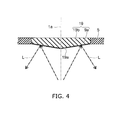
- FIG. 4 is a schematic sectional view for illustrating a reflecting section 19 having an inclined surface.
- the reflecting section 19 has a reflecting section body 19b and the aforementioned reflecting layer 9a.
- An inclined surface 19a is provided on the light source 3 side of the reflecting section body 19b.
- the aforementioned reflecting layer 9a is provided on the inclined surface 19a.
- the reflecting layer 9a may be provided on the entire surface of the reflecting section body 19b.
- the inclined surface 19a can be inclined in a direction made close to the light source 3 toward the center side of the reflecting section body 19b.
- the inclined surface 19a can be a flat surface or curved surface.
- the inclined surface 19a is provided symmetrically about the central axis 1a of the lighting device 1. If the inclined surface 19a is symmetric about the central axis 1a of the lighting device 1, the light can be radiated symmetrically about the central axis 1a.
- the inclination angle of the inclined surface 19a is not particularly limited.
- the inclination angle of the inclined surface 19a can be appropriately changed depending on the distance between the light source 3 and the reflecting section 19 and the outline dimension of the reflecting section 19.
- the light L radiated from the light source 3 and directed to the reflecting section 19 is reflected by the reflecting layer 9a provided on the inclined surface 19a and radiated to the lateral side and the rear side of the lighting device 1.
- the inclined surface 19a is inclined so as to be made close to the light source 3 side toward the center side of the reflecting section 19.
- the incident light is easily radiated to the lateral side and the rear side of the lighting device 1.
- the light distribution angle can be further expanded.
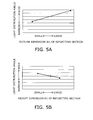
- FIG. 5A is a schematic graph for illustrating the relationship between the outline dimension W1 of the reflecting section 9 and the light distribution angle.
- the outline dimension W1 of the reflecting section 9 is the dimension of the reflecting section 9 in the direction perpendicular to the central axis 1a of the lighting device 1 as shown in FIG. 1 .
- the outline dimension W1 of the reflecting section 9 is the diameter dimension of the disk.
- the light distribution angle can be expanded.
- the outline dimension W1 of the reflecting section 9 is excessively increased, the light radiated to the front side of the lighting device 1 may be excessively decreased.
- the outline dimension W1 of the reflecting section 9 is preferably made smaller than the outermost diameter dimension W3 of the globe 5.
- the outline dimension W1 of the reflecting section 9 is preferably made smaller than the outline dimension W2 of the substrate 8.
- the light is radiated easily to the front side of the lighting device 1 via the outside of the reflecting section 9.
- FIG. 5B is a schematic graph for illustrating the relationship between the height dimension H1 being the attachment position of the reflecting section 9 and the light distribution angle.
- the height dimension H1 of the reflecting section 9 is the dimension between the end portion 2a of the body section 2 and the surface on the light source 3 side of the reflecting section 9 as shown in FIG. 1 .
- the light distribution angle can be expanded.
- the light distribution angle can be expanded by increasing the outline dimension W1 of the reflecting section 9 or decreasing the height dimension H1 of the reflecting section 9.
- the light distribution angle can be made nearly three times compared with that illustrated in FIG. 3 .
- FIG. 6A is a schematic graph for illustrating the relationship between the thickness of the globe 5 and the light distribution angle.
- the light distribution angle is expanded more easily when the thickness T1 on the light source 3 side of the globe 5 is made thinner than the thickness T2 on the reflecting section 9 side of the globe 5 as shown in FIG. 1 , rather than when the thickness T1 on the light source 3 side of the globe 5 and the thickness T2 on the reflecting section 9 side of the globe 5 are made equal in dimension.
- FIG. 6B is a schematic graph for illustrating the relationship between the height dimension H2 of the outermost diameter portion of the globe 5 and the light distribution angle.
- the light distribution angle can be expanded.
- the light distribution angle is expanded more easily when the outermost diameter dimension W3 of the globe 5 is made larger than the diameter dimension of the end portion 2a of the body section 2.
- the outline dimension of the portion of the globe 5 in contact with the end portion 2a is made smaller than the outermost diameter dimension W3 of the globe 5.
- the outermost diameter dimension W3 of the globe 5 in the portion provided with the groove can be made larger than the dimension of the body section 2.
- the light distribution angle is expanded more easily by providing e.g. a groove in the outer peripheral surface of the body section 2.
- the light distribution angle can be expanded by making the thickness T1 on the light source 3 side of the globe 5 thinner than the thickness T2 on the reflecting section 9 side of the globe 5 or increasing the height dimension H2 of the outermost diameter portion of the globe 5.
- the light distribution angle can be made nearly three times compared with that illustrated in FIG. 3 .
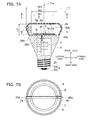
- FIGS. 7A and 7B are schematic partial sectional views for illustrating a lighting device according to a second embodiment.
- FIG. 7A is a schematic partial sectional view of the lighting device 11.
- FIG. 7B is a view taken in the direction of arrows A-A in FIG. 7A .
- the lighting device 11 includes a body section 2, a light source 3, a globe 5, a base section 6, a control section 7, and a reflecting section 9.
- the lighting device 11 includes a heat transfer section 29.
- the heat generated in the light source 3 is dissipated to the outside through the substrate 8 and the body section 2 by thermal conduction.
- the heat generated in the light source 3 is dissipated to the outside through the reflecting section 9 by radiation and convection.
- the heat transfer section 29 is further provided.
- the heat transfer section 29 is provided inside the globe 5.
- the end portion 29a on the globe 5 side of the heat transfer section 29 is exposed from the globe 5.
- the end portion 29b on the body section 2 side of the heat transfer section 29 is at least partly in thermal contact with the end portion 2a of the body section 2.
- the end portion 29c of the heat transfer section 29 is at least partly in thermal contact with the substrate 8.
- the end portion 29d of the heat transfer section 29 is at least partly in thermal contact with the radiation surface 3a of the light source 3.
- the end portion 29e on the reflecting section 9 side of the heat transfer section 29 is at least partly in thermal contact with the reflecting section 9.
- the end portion 29b, the end portion 29c, the end portion 29d, and the end portion 29e do not necessarily need to be all in thermal contact, but it is sufficient that at least one of them be in thermal contact.
- the end portion 29e may be in thermal contact with the globe 5 without being exposed from the globe 5.
- thermal contact means that heat is transferred between the heat transfer section 29 and the mating member by at least one of thermal conduction, convection, and radiation.
- the heat transfer section 29 may be abutted to transfer heat by thermal conduction.
- a small gap to the heat transfer section 29 may be provided to transfer heat by convection and radiation.
- the end portions 29a-29e of the heat transfer section 29 may be abutted to the mating member, or may be spaced therefrom to the extent that heat can be transferred.
- the end portions 29a-29e of the heat transfer section 29 are preferably abutted to the mating member.
- the thermal contact is not necessarily needed in the entire region of the end portions, but only needed in at least part of the end portions.
- At least one of the end portion 2a of the body section 2, the substrate 8, and the radiation surface 3a of the light source 3 serves as a heat dissipation surface on the end portion 2a side of the body section 2.
- the end portion of the heat transfer section 29 only needs to be at least partly in thermal contact with the heat dissipation surface on the end portion 2a side of the body section 2.
- the end portion of the heat transfer section 29 only needs to be at least partly in thermal contact with the reflecting section 9.
- thermal contact is provided in as large a region as possible.
- a contact section including a material having high thermal conductivity can be provided between the end portion of the heat transfer section 29 and the heat dissipation surface on the end portion 2a side of the body section 2.
- the end portion 2a of the body section 2 and the end portion 29b of the heat transfer section 29 can be bonded with e.g. solder to provide a contact section.
- the substrate 8 and the end portion 29c of the heat transfer section 29 can be bonded with e.g. solder to provide a contact section.
- the radiation surface 3a of the light source 3 and the end portion 29d of the heat transfer section 29 can be bonded with e.g. a high heat transfer adhesive added with ceramic filler having high thermal conductivity to provide a contact section.
- the reflecting section 9 and the end portion 29e of the heat transfer section 29 can be bonded with e.g. solder to provide a contact section.
- a contact section including a material having high thermal conductivity can be provided between the inner surface of the globe 5 and the end portion 29a of the heat transfer section 29.
- the inner surface of the globe 5 and the end portion 29a of the heat transfer section 29 can be bonded with e.g. a high heat transfer adhesive added with ceramic filler having high thermal conductivity to provide a contact section.
- the end portions 29a-29e of the heat transfer section 29 may be brought into thermal contact with the mating side simply by abutment. However, if the end portions 29a-29e of the heat transfer section 29 are brought into contact with the mating side via a contact section including a material having high thermal conductivity, the thermal resistance can be decreased. Thus, the heat dissipation effect can be further improved.
- the heat transfer section 29 and the reflecting section body 9b may be integrally formed.
- the heat transfer section 29, the reflecting section body 9b, and the body section 2 may be integrally formed. Then, the heat dissipation effect can be further improved.
- the heat transfer section 29 can be formed from a material having high thermal conductivity.
- the heat transfer section 29 can be formed from e.g. a metal material such as aluminum (Al), copper (Cu), and magnesium alloy. However, the material is not limited thereto.
- the heat transfer section 29 can also be formed from e.g. an inorganic material such as aluminum nitride (AIN), or an organic material such as high thermal conductivity resin.
- the heat transfer section 29 is simply provided inside the globe 5, the difference between the light portion and the dark portion occurring on the globe 5 is increased. This may increase the brightness unevenness in the lighting device 11.
- the heat transfer section 29 is configured to be able to reflect the light radiated from the light source 3.
- the heat transfer section 29 can be configured to have higher reflectance than the globe 5.
- the heat transfer section 29 can be configured to have a reflecting layer 30 on its surface.
- the reflecting layer 30 thus provided is preferably such that, for instance, the reflectance to the light radiated from the light source 3 is 90% or more.
- the reflecting layer 30 can be made similar to the aforementioned reflecting layer 9a.
- the reflecting layer 30 can be a layer formed by applying e.g. white resin to the surface of the heat transfer section 29.
- the reflecting layer 30 is not limited thereto, but can be a layer formed from a material such that the reflectance to the light radiated from the light source 3 is 90% or more.
- the reflecting layer 30 can be a layer formed by coating with a metal having high reflectance such as silver and aluminum.
- the color of the resin is not limited to white, but can be appropriately changed.
- the method for forming the reflecting layer 30 is not limited to application and coating.
- the reflecting layer 30 may also be previously formed into a film shape and bonded to the surface of the heat transfer section 29.
- the heat transfer section 29 itself may be formed from a material having high reflectance.
- the heat transfer section 29 can be shaped like a plate.
- the heat transfer section 29 shaped like a plate facilitates integrally forming the reflecting section 9 and the heat transfer section 29.
- the shape of the heat transfer section 29 is not limited thereto, but can be appropriately changed.
- the heat transfer section 29 can be configured to have an intersecting form of a plurality of plate-like bodies.
- the heat transfer section 39 can be configured to have a crossed form of two plate-like bodies.
- the heat transfer section 29 can be configured to have a shape rotationally symmetric about the central axis 11a of the lighting device 11.
- the heat transfer section 29 has a shape rotationally symmetric about the central axis 11a of the lighting device 11, the brightness in the respective regions defined by the heat transfer section 29 in the globe 5 can be made equivalent to each other.
- the difference between the light portion and the dark portion occurring on the globe 5 can be decreased. This can decrease the brightness unevenness in the lighting device 11.
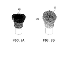
- FIGS. 8A and 8B are schematic views for illustrating heat dissipation in the lighting device.
- FIG. 8A is a schematic view for illustrating the temperature distribution near the end portion 2a of the body section 2 in the case where the heat transfer section 39 is not provided.
- FIG. 8B is a schematic view for illustrating the temperature distribution near the end portion 2a of the body section 2 in the case where the heat transfer section 39 having a crossed form of two plate-like bodies is provided.
- FIGS. 8A and 8B show the temperature distributions of the lighting device determined by simulation, with the output of the light source 3 set to approximately 5 W (watts), and the ambient temperature set to approximately 25°C.
- the temperature distribution is represented by monotone shading, with a higher temperature shaded darker and a lower temperature shaded lighter.
- the heat transfer section 39 heat can be dissipated also from the globe 5 side.
- the heat dissipation of the lighting device 11 can be improved. Accordingly, the lifetime of the lighting device 11 can be prolonged. Furthermore, the basic performance of the lighting device 11 such as higher luminous flux can be improved.
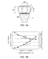
- FIGS. 9A and 9B are schematic views for illustrating a heat transfer section having an opening.
- FIG. 9A is a schematic partial sectional view for illustrating the heat transfer section having an opening.
- FIG. 9B is a schematic graph for illustrating the effect of providing an opening.
- the heat transfer section 49 includes an opening 49a with height dimension H3.
- the heat transfer section 49 has an opening 49a penetrating in its thickness direction.
- the light source 3 can be provided on the end portion 2a of the body section 2. Then, the heat transfer section 49 is provided at the position blocking the light radiated from the light source 3.
- FIG. 9B illustrates the case of changing the height dimension H3 of the opening 49a.
- FIG. 9B illustrates the case of changing the width dimension W4 of the opening 49a. That is, also by increasing the width dimension W4 of the opening 49a, the light extraction efficiency can be increased.
- the limit electrical power the electrical power which can be inputted to the light emitting element 3b. Then, if the limit electrical power is decreased, the amount of light radiated from the light source 3 is decreased.
- the size of the opening 49a can be appropriately determined by taking into consideration the characteristics of the light emitting element 3b, the increase of light extraction efficiency achieved by providing the opening 49a, and the decrease of heat dissipation due to the provision of the opening 49a.
- the opening 49a opens in the end portion on the body section 2 side of the heat transfer section 49.
- the shape of the opening 49a and the position for providing the opening 49a can be appropriately changed.
- the light extraction efficiency can be increased by providing the opening 49a at a position closer to the light source 3.
- the opening 49a is preferably configured so as to open in the end portion on the body section 2 side of the heat transfer section 49.
- FIG. 10 is a schematic partial sectional view for illustrating an opening according to an alternative embodiment.
- the opening 59a provided in the heat transfer section 59 opens in the end portion on the body section 2 side and the end portion on the globe 5 side of the heat transfer section 59.
- the heat transfer section 59 is in contact with the substrate 8 on the center side and extends to the reflecting section 9 side.
- the heat transfer section 59 extends outward from the central axis of the lighting device along the shape of the globe 5.
- the cross section of the heat transfer section 59 including the central axis of the lighting device is shaped like an umbrella.
- the opening 59a opens in the end portion on the globe 5 side of the heat transfer section 59. Then, as shown in FIG. 10 , the light L1 radiated from the light source 3 and reflected at the reflecting section 9, and the light L2 reflected at the end surface of the lens 40, are radiated to the rear side of the lighting device. Thus, the light extraction efficiency can be increased, and the light distribution angle can be expanded.
- This heat transfer section 59 can be entirely composed of one plate as shown in FIG. 10 .
- the left half plate-like body and the right half plate-like body may be integrally formed, and these two plate-like bodies may be linked at e.g. the position indicated by the dashed line of FIG. 10 .
- the left half plate-like body and the right half plate-like body in FIG. 10 may be composed of separate bodies and connected on the dashed line of FIG. 10 .
- another separate plate-like body (not shown) may be added. The added plate-like body is brought into thermal contact with the heat transfer section 59 on the dashed line shown in FIG. 10 , and can constitute part of the heat transfer section 59.
- the light sources 3 can be arranged in an annular configuration. Furthermore, the light source 3 can be provided near the globe 5.
- an optical element such as an annular lens 40 can be easily provided.
- the opening 59a is configured to open at a position closer to the body section 2, the light extraction efficiency can be further increased, and the light distribution angle can be further expanded.
- the opening can be configured to open in at least one of the end portion on the body section side of the heat transfer section and the end portion on the globe 5 side of the heat transfer section.
- the foregoing relates to the case of expanding the light distribution angle.
- the embodiments are applicable also to the case of adjusting the light distribution angle depending on the purpose and the like of the lighting device.
- a light distribution angle adapted to the purpose and the like of the lighting device can also be obtained by appropriately setting e.g. the inclination angle of the inclined surface 19a of the reflecting section 19, the outline dimension W1 of the reflecting section 9, the attachment position (height dimension H1) of the reflecting section 9, the thickness T1, T2 of the globe 5, the height dimension H2 of the outermost diameter portion of the globe 5, and the opening position of the opening 59a of the heat transfer section 59 described above.
- a translucent section 69 can be provided in the reflecting section 9 so that light is easily radiated to the front side of the lighting device.
- FIG. 11 is a schematic sectional view for illustrating the translucent section 69 provided in the reflecting section 9.
- the translucent section 69 is provided in a hole penetrating in the thickness direction of the reflecting section 9.
- the translucent section 69 is formed from a translucent material.
- the translucent section 69 can be formed from e.g. the same material as the globe 5.
- the light L3 radiated from the light source 3 and being incident on the reflecting section 9 is reflected.
- the light L4 incident on the translucent section 69 is transmitted through the translucent section 69 and radiated to the front side of the lighting device.
- light is easily radiated to the front side of the lighting device.
- the size, number, layout, shape and the like of the translucent section 69 are not particularly limited, but can be appropriately set depending on the light distribution characteristics required by the purpose and the like of the lighting device.
Landscapes
- Engineering & Computer Science (AREA)
- General Engineering & Computer Science (AREA)
- Physics & Mathematics (AREA)
- Microelectronics & Electronic Packaging (AREA)
- Optics & Photonics (AREA)
- Non-Portable Lighting Devices Or Systems Thereof (AREA)
- Arrangement Of Elements, Cooling, Sealing, Or The Like Of Lighting Devices (AREA)
Applications Claiming Priority (1)
| Application Number | Priority Date | Filing Date | Title |
|---|---|---|---|
| JP2012148047A JP2014011088A (ja) | 2012-06-29 | 2012-06-29 | 照明装置 |
Publications (1)
| Publication Number | Publication Date |
|---|---|
| EP2679896A1 true EP2679896A1 (de) | 2014-01-01 |
Family
ID=47998168
Family Applications (1)
| Application Number | Title | Priority Date | Filing Date |
|---|---|---|---|
| EP13159418.6A Withdrawn EP2679896A1 (de) | 2012-06-29 | 2013-03-15 | Beleuchtungsvorrichtung |
Country Status (4)
| Country | Link |
|---|---|
| US (1) | US20140003057A1 (de) |
| EP (1) | EP2679896A1 (de) |
| JP (1) | JP2014011088A (de) |
| CN (1) | CN203348957U (de) |
Cited By (2)
| Publication number | Priority date | Publication date | Assignee | Title |
|---|---|---|---|---|
| EP2927561A1 (de) * | 2014-03-31 | 2015-10-07 | Radiant Opto-Electronics Corporation | Leuchte |
| US9709240B2 (en) | 2014-03-31 | 2017-07-18 | Radiant Opto-Electronics Corporation | Lamp |
Families Citing this family (2)
| Publication number | Priority date | Publication date | Assignee | Title |
|---|---|---|---|---|
| JP6206266B2 (ja) * | 2014-03-14 | 2017-10-04 | 東芝ライテック株式会社 | 車両用発光モジュール、車両用照明装置、および車両用灯具 |
| FR3054046B1 (fr) * | 2016-06-29 | 2018-08-17 | Valeo Comfort And Driving Assistance | Dispositif de generation d'images et afficheur tete haute associe |
Citations (5)
| Publication number | Priority date | Publication date | Assignee | Title |
|---|---|---|---|---|
| GB2460703A (en) * | 2008-06-07 | 2009-12-09 | Yu-Chen Chang | Light-transmittable cover for a light emitting diode bulb |
| US20100254128A1 (en) * | 2009-04-06 | 2010-10-07 | Cree Led Lighting Solutions, Inc. | Reflector system for lighting device |
| DE202011000929U1 (de) * | 2011-04-19 | 2011-08-11 | Jade Yang Co., Ltd. | LED-Lampe mit reflektierbaren Beleuchtungen |
| CN102305363A (zh) * | 2011-08-30 | 2012-01-04 | 厦门立明光电有限公司 | 大角度全向照明led灯 |
| US20120161626A1 (en) * | 2010-12-22 | 2012-06-28 | Cree, Inc. | Led lamp with high color rendering index |
-
2012
- 2012-06-29 JP JP2012148047A patent/JP2014011088A/ja active Pending
-
2013
- 2013-03-15 US US13/832,814 patent/US20140003057A1/en not_active Abandoned
- 2013-03-15 EP EP13159418.6A patent/EP2679896A1/de not_active Withdrawn
- 2013-03-29 CN CN2013201506045U patent/CN203348957U/zh not_active Expired - Fee Related
Patent Citations (5)
| Publication number | Priority date | Publication date | Assignee | Title |
|---|---|---|---|---|
| GB2460703A (en) * | 2008-06-07 | 2009-12-09 | Yu-Chen Chang | Light-transmittable cover for a light emitting diode bulb |
| US20100254128A1 (en) * | 2009-04-06 | 2010-10-07 | Cree Led Lighting Solutions, Inc. | Reflector system for lighting device |
| US20120161626A1 (en) * | 2010-12-22 | 2012-06-28 | Cree, Inc. | Led lamp with high color rendering index |
| DE202011000929U1 (de) * | 2011-04-19 | 2011-08-11 | Jade Yang Co., Ltd. | LED-Lampe mit reflektierbaren Beleuchtungen |
| CN102305363A (zh) * | 2011-08-30 | 2012-01-04 | 厦门立明光电有限公司 | 大角度全向照明led灯 |
Cited By (3)
| Publication number | Priority date | Publication date | Assignee | Title |
|---|---|---|---|---|
| EP2927561A1 (de) * | 2014-03-31 | 2015-10-07 | Radiant Opto-Electronics Corporation | Leuchte |
| US9709240B2 (en) | 2014-03-31 | 2017-07-18 | Radiant Opto-Electronics Corporation | Lamp |
| US9719659B2 (en) | 2014-03-31 | 2017-08-01 | Radiant Opto-Electronics Corporation | Lamp |
Also Published As
| Publication number | Publication date |
|---|---|
| CN203348957U (zh) | 2013-12-18 |
| JP2014011088A (ja) | 2014-01-20 |
| US20140003057A1 (en) | 2014-01-02 |
Similar Documents
| Publication | Publication Date | Title |
|---|---|---|
| US10557594B2 (en) | Solid-state lamps utilizing photoluminescence wavelength conversion components | |
| JP5263515B2 (ja) | 照明装置 | |
| CN114731748A (zh) | Led灯丝以及led灯丝灯 | |
| US20110103055A1 (en) | Led-based light bulb device with kelvin corrective features | |
| EP2667085A1 (de) | Glühbirnenförmige leuchte und beleuchtungsvorrichtung | |
| CN103003624A (zh) | 发光二极管聚光灯 | |
| US20120212959A1 (en) | Lighting device | |
| US8911105B2 (en) | LED lamp with shaped light distribution | |
| CN102893073B (zh) | 带有双重漫射器的led模块 | |
| CN102997088B (zh) | 照明装置 | |
| EP2679896A1 (de) | Beleuchtungsvorrichtung | |
| JP5802497B2 (ja) | 電球型照明装置 | |
| JP5320627B2 (ja) | 口金付ランプおよび照明器具 | |
| JP7053968B2 (ja) | 固体ランプ | |
| JP2011113861A (ja) | 口金付ランプおよび照明器具 | |
| JP5537612B2 (ja) | 照明装置 | |
| US20140240955A1 (en) | Luminaire | |
| JP5824680B2 (ja) | ランプ及び照明装置 | |
| CN103133921B (zh) | 灯泡形照明装置 |
Legal Events
| Date | Code | Title | Description |
|---|---|---|---|
| PUAI | Public reference made under article 153(3) epc to a published international application that has entered the european phase |
Free format text: ORIGINAL CODE: 0009012 |
|
| 17P | Request for examination filed |
Effective date: 20130315 |
|
| AK | Designated contracting states |
Kind code of ref document: A1 Designated state(s): AL AT BE BG CH CY CZ DE DK EE ES FI FR GB GR HR HU IE IS IT LI LT LU LV MC MK MT NL NO PL PT RO RS SE SI SK SM TR |
|
| AX | Request for extension of the european patent |
Extension state: BA ME |
|
| STAA | Information on the status of an ep patent application or granted ep patent |
Free format text: STATUS: THE APPLICATION HAS BEEN WITHDRAWN |
|
| 18W | Application withdrawn |
Effective date: 20141009 |