EP2679924A2 - Ventilation apparatus capable of recovering thermal energy - Google Patents
Ventilation apparatus capable of recovering thermal energy Download PDFInfo
- Publication number
- EP2679924A2 EP2679924A2 EP12749901.0A EP12749901A EP2679924A2 EP 2679924 A2 EP2679924 A2 EP 2679924A2 EP 12749901 A EP12749901 A EP 12749901A EP 2679924 A2 EP2679924 A2 EP 2679924A2
- Authority
- EP
- European Patent Office
- Prior art keywords
- air
- main body
- exhaust
- supply
- ventilation apparatus
- Prior art date
- Legal status (The legal status is an assumption and is not a legal conclusion. Google has not performed a legal analysis and makes no representation as to the accuracy of the status listed.)
- Withdrawn
Links
- 238000009423 ventilation Methods 0.000 title claims abstract description 43
- XLYOFNOQVPJJNP-UHFFFAOYSA-N water Substances O XLYOFNOQVPJJNP-UHFFFAOYSA-N 0.000 claims abstract description 38
- 238000010521 absorption reaction Methods 0.000 claims abstract description 32
- 238000007664 blowing Methods 0.000 claims abstract description 14
- 238000007599 discharging Methods 0.000 claims abstract description 7
- 238000001816 cooling Methods 0.000 claims description 8
- 238000004378 air conditioning Methods 0.000 description 11
- 238000010438 heat treatment Methods 0.000 description 5
- 238000000034 method Methods 0.000 description 5
- CURLTUGMZLYLDI-UHFFFAOYSA-N Carbon dioxide Chemical compound O=C=O CURLTUGMZLYLDI-UHFFFAOYSA-N 0.000 description 2
- 230000002950 deficient Effects 0.000 description 2
- 238000005516 engineering process Methods 0.000 description 2
- 238000001704 evaporation Methods 0.000 description 2
- 230000008020 evaporation Effects 0.000 description 2
- 238000009434 installation Methods 0.000 description 2
- 239000011229 interlayer Substances 0.000 description 2
- 239000010410 layer Substances 0.000 description 2
- 238000003303 reheating Methods 0.000 description 2
- 239000008400 supply water Substances 0.000 description 2
- 241000700605 Viruses Species 0.000 description 1
- QVGXLLKOCUKJST-UHFFFAOYSA-N atomic oxygen Chemical compound [O] QVGXLLKOCUKJST-UHFFFAOYSA-N 0.000 description 1
- 229910002092 carbon dioxide Inorganic materials 0.000 description 1
- 239000001569 carbon dioxide Substances 0.000 description 1
- 239000000428 dust Substances 0.000 description 1
- 238000005265 energy consumption Methods 0.000 description 1
- 239000007789 gas Substances 0.000 description 1
- 230000004060 metabolic process Effects 0.000 description 1
- 238000012986 modification Methods 0.000 description 1
- 230000004048 modification Effects 0.000 description 1
- 229910052760 oxygen Inorganic materials 0.000 description 1
- 239000001301 oxygen Substances 0.000 description 1
- 238000011144 upstream manufacturing Methods 0.000 description 1
Images



Classifications
-
- F—MECHANICAL ENGINEERING; LIGHTING; HEATING; WEAPONS; BLASTING
- F24—HEATING; RANGES; VENTILATING
- F24F—AIR-CONDITIONING; AIR-HUMIDIFICATION; VENTILATION; USE OF AIR CURRENTS FOR SCREENING
- F24F7/00—Ventilation
- F24F7/04—Ventilation with ducting systems, e.g. by double walls; with natural circulation
- F24F7/06—Ventilation with ducting systems, e.g. by double walls; with natural circulation with forced air circulation, e.g. by fan positioning of a ventilator in or against a conduit
- F24F7/08—Ventilation with ducting systems, e.g. by double walls; with natural circulation with forced air circulation, e.g. by fan positioning of a ventilator in or against a conduit with separate ducts for supplied and exhausted air with provisions for reversal of the input and output systems
-
- F—MECHANICAL ENGINEERING; LIGHTING; HEATING; WEAPONS; BLASTING
- F24—HEATING; RANGES; VENTILATING
- F24F—AIR-CONDITIONING; AIR-HUMIDIFICATION; VENTILATION; USE OF AIR CURRENTS FOR SCREENING
- F24F12/00—Use of energy recovery systems in air conditioning, ventilation or screening
- F24F12/001—Use of energy recovery systems in air conditioning, ventilation or screening with heat-exchange between supplied and exhausted air
- F24F12/006—Use of energy recovery systems in air conditioning, ventilation or screening with heat-exchange between supplied and exhausted air using an air-to-air heat exchanger
-
- F—MECHANICAL ENGINEERING; LIGHTING; HEATING; WEAPONS; BLASTING
- F24—HEATING; RANGES; VENTILATING
- F24F—AIR-CONDITIONING; AIR-HUMIDIFICATION; VENTILATION; USE OF AIR CURRENTS FOR SCREENING
- F24F13/00—Details common to, or for air-conditioning, air-humidification, ventilation or use of air currents for screening
- F24F13/28—Arrangement or mounting of filters
-
- F—MECHANICAL ENGINEERING; LIGHTING; HEATING; WEAPONS; BLASTING
- F24—HEATING; RANGES; VENTILATING
- F24F—AIR-CONDITIONING; AIR-HUMIDIFICATION; VENTILATION; USE OF AIR CURRENTS FOR SCREENING
- F24F3/00—Air-conditioning systems in which conditioned primary air is supplied from one or more central stations to distributing units in the rooms or spaces where it may receive secondary treatment; Apparatus specially designed for such systems
- F24F3/12—Air-conditioning systems in which conditioned primary air is supplied from one or more central stations to distributing units in the rooms or spaces where it may receive secondary treatment; Apparatus specially designed for such systems characterised by the treatment of the air otherwise than by heating and cooling
- F24F3/14—Air-conditioning systems in which conditioned primary air is supplied from one or more central stations to distributing units in the rooms or spaces where it may receive secondary treatment; Apparatus specially designed for such systems characterised by the treatment of the air otherwise than by heating and cooling by humidification; by dehumidification
-
- F—MECHANICAL ENGINEERING; LIGHTING; HEATING; WEAPONS; BLASTING
- F24—HEATING; RANGES; VENTILATING
- F24F—AIR-CONDITIONING; AIR-HUMIDIFICATION; VENTILATION; USE OF AIR CURRENTS FOR SCREENING
- F24F7/00—Ventilation
- F24F7/003—Ventilation in combination with air cleaning
-
- F—MECHANICAL ENGINEERING; LIGHTING; HEATING; WEAPONS; BLASTING
- F24—HEATING; RANGES; VENTILATING
- F24F—AIR-CONDITIONING; AIR-HUMIDIFICATION; VENTILATION; USE OF AIR CURRENTS FOR SCREENING
- F24F8/00—Treatment, e.g. purification, of air supplied to human living or working spaces otherwise than by heating, cooling, humidifying or drying
- F24F8/10—Treatment, e.g. purification, of air supplied to human living or working spaces otherwise than by heating, cooling, humidifying or drying by separation, e.g. by filtering
- F24F8/117—Treatment, e.g. purification, of air supplied to human living or working spaces otherwise than by heating, cooling, humidifying or drying by separation, e.g. by filtering using wet filtering
-
- F—MECHANICAL ENGINEERING; LIGHTING; HEATING; WEAPONS; BLASTING
- F24—HEATING; RANGES; VENTILATING
- F24F—AIR-CONDITIONING; AIR-HUMIDIFICATION; VENTILATION; USE OF AIR CURRENTS FOR SCREENING
- F24F13/00—Details common to, or for air-conditioning, air-humidification, ventilation or use of air currents for screening
- F24F13/22—Means for preventing condensation or evacuating condensate
- F24F13/222—Means for preventing condensation or evacuating condensate for evacuating condensate
- F24F2013/225—Means for preventing condensation or evacuating condensate for evacuating condensate by evaporating the condensate in the cooling medium, e.g. in air flow from the condenser
-
- F—MECHANICAL ENGINEERING; LIGHTING; HEATING; WEAPONS; BLASTING
- F24—HEATING; RANGES; VENTILATING
- F24F—AIR-CONDITIONING; AIR-HUMIDIFICATION; VENTILATION; USE OF AIR CURRENTS FOR SCREENING
- F24F2221/00—Details or features not otherwise provided for
- F24F2221/34—Heater, e.g. gas burner, electric air heater
-
- Y—GENERAL TAGGING OF NEW TECHNOLOGICAL DEVELOPMENTS; GENERAL TAGGING OF CROSS-SECTIONAL TECHNOLOGIES SPANNING OVER SEVERAL SECTIONS OF THE IPC; TECHNICAL SUBJECTS COVERED BY FORMER USPC CROSS-REFERENCE ART COLLECTIONS [XRACs] AND DIGESTS
- Y02—TECHNOLOGIES OR APPLICATIONS FOR MITIGATION OR ADAPTATION AGAINST CLIMATE CHANGE
- Y02B—CLIMATE CHANGE MITIGATION TECHNOLOGIES RELATED TO BUILDINGS, e.g. HOUSING, HOUSE APPLIANCES OR RELATED END-USER APPLICATIONS
- Y02B30/00—Energy efficient heating, ventilation or air conditioning [HVAC]
- Y02B30/56—Heat recovery units
Definitions
- the present invention disclosed herein relates to a ventilation apparatus of recovering thermal energy, and more particularly, to a ventilation apparatus of recovering thermal energy without a loss in a process of ventilating indoor air.
- the air conditioning apparatus may reoperate due to a temperature difference the temperature of the introduced air and the setting temperature.
- the ventilation time of the building tends to be limited.
- exhaust heat recovering apparatuses are recently being developed and used to recover exhaust heat by exchanging heat between indoor air discharged out of the room and outdoor air supplied into the room.
- exhaust air air supply and exhaust ports 110 and 120 that allow air (hereinafter, referred to as “exhaust air”) discharged out of the room and air (hereinafter, referred to as “supply air”) supplied into the room to pass therethrough
- supply air air supplied into the room to pass therethrough
- an heat exchanger 130 is provided to allow supply air and exhaust air passing along the air supply and exhaust ports 110 and 120 to pass through different passages.
- This technology uses only the heat exchanger 130 to heat exchange between supply air and exhaust air. In spite of the heat exchange between supply air and exhaust air, exhaust heat cannot be completely recovered. Accordingly, even though outdoor air to which exhaust heat is recovered is introduced into the room, a temperature difference occurs between the indoor temperature and the setting temperature, causing the reoperation of the air conditioning apparatus and thus the consumption of energy.
- the present invention provides a ventilation apparatus for recovering thermal energy, which can prevent energy consumption due to the reoperation of an air conditioning apparatus caused by a temperature difference between indoor air and outdoor air to which exhaust heat is recovered during the introduction of outdoor air into the room.
- the present invention also provides a ventilation apparatus of recovering thermal energy, which can also be used as a humidifier by ventilating a room in winter season.
- Embodiments of the present invention provide ventilation apparatuses for a building to recover thermal energy, including: a main body having air exhaust ports for discharging indoor air out of the building and air supply ports for supplying outdoor air into the building; an absorption filter disposed in the main body to cool exhaust air; a heat exchanger disposed in the main body to exchange heat between supply air and exhaust air; first and second blowing fans disposed in the main body, the first blowing fan discharging indoor air and the second blowing fan supplying outdoor air; and a water supply pipe for supplying water to the absorption filter.
- water supplied through the water supply pipe may be condensate water of an air conditioning apparatus.
- FIG. 1 is a cross-sectional view illustrating a typical exhaust heat recovering apparatus
- FIG. 2 is a perspective view illustrating a ventilation apparatus of recovering thermal energy according to an embodiment of the present invention
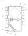
- FIG. 3 is a cross-sectional view of FIG. 2 ;
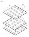
- FIG. 4 is an exploded perspective view illustrating a heat exchanger according to an embodiment of the present invention.
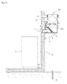
- FIG. 5 is a view illustrating a configuration of a ventilation apparatus of recovering thermal energy according to an embodiment of the present invention
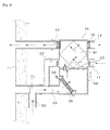
- FIG. 6 is a view illustrating an exemplary use of a ventilation apparatus of recovering thermal energy during the summer season according to an embodiment of the present invention
- FIG. 7 is a view illustrating an exemplary use of a ventilation apparatus of recovering thermal energy during the winter season according to an embodiment of the present invention.
- FIG. 8 is a view illustrating another exemplary use of a ventilation apparatus of recovering thermal energy according to an embodiment of the present invention.
- the present invention relates to a ventilation apparatus of recovering thermal energy to minimize a loss of thermal energy generated during the ventilation of indoor air when air conditioning is performed in buildings such as plants, apartments, and high-rise buildings.
- the ventilation apparatus may include a main body 10, an absorption filter 20, a heat exchanger 30, a pair of blowing fans 40, and a water supply pipe 50.
- the main body 10 may have a space in which the absorption filter 20, the heat exchanger 30, the blowing fan 40, and the water supply pipe 50 described later are installed, air supply ports 11 and 12 for supplying outdoor air into a room, and air exhaust ports 13 and 14.
- a plurality of doors may be disposed at the air supply port 11 through which outdoor air is introduced into the main body 10.
- the plurality of door may serve to control the open degree of the air supply port 11.
- the open degree of the doors may be automatically controlled by a controller 60.
- a water supply pipe 50 may be disposed at one side of the main body 10 to supply water to the absorption filter 20 disposed therein, and a water discharge pipe 17 may be disposed under the absorption filter 20 to discharge supplied water out of the main body 10.
- an open/close door 15 may be provided to change the flow passage of exhaust air according to the summer season and winter season, and a temperature and humidity sensor 18 may be further provided to sense the temperature and the humidity of exhaust air supplied into the main body 10.
- a heater core 16 may be further provided to compensate for a deficient temperature upon the heat exchange between supply air and exhaust air by reheating supply air during the winter season.
- the heater core 16 may be implemented using an electric heater.
- the heater core 16 may be configured to rotate about one end, if necessary, between air passages to allow supply air passing therethrough to be heated.
- the absorption filter 20 may be manufactured to have a sectional shape of lattice, wave or honeycomb, and may have an air passage communicating both sides thereof. When exhaust air passes along the air passage, exhaust air may be cooled by the absorption filter 20 soaked by water.
- the absorption filter 20 is being widely used in a technology of generating cold wind using heat of evaporation as in an evaporation-typed cold air blower and an evaporation-typed humidifier. Since the absorption filter 20 can be easily selected or modified into various types by those skilled in the art, a detailed description thereof will be omitted herein.
- the absorption filter 20 may be disposed in plurality at the side surface of the main body 10, and exhaust air ports 13 may also be formed to communicate with the plurality of absorption filters 20, respectively.
- the heat exchanger 30 may be configured to be disposed inside the main body 10 to allow supply air and exhaust air to cross each other and flow into different layers.
- a plate-type heat exchanger is being widely used as the heat exchanger 30.
- the plate-type heat exchanger may include first and second heat transfer plates 31 and 32 alternately stacked, and may indirectly exchange heat between supply air and exhaust air by allowing heat to be transferred to the first and second heat transfer plates 31 and 32 while supply air and exhaust air pass between the heat transfer plates.
- the blowing fan 40 may be disposed in the air supply port 12 and the air exhaust port 14 at the downstream side or the air supply port 11 and the air exhaust port 13 at the upstream side to transfer supply air and exhaust air to/from the main body 10, respectively.
- the water supply pipe 50 may be disposed at the upper portion of the absorption filter 20 to supply water to the absorption filter 20.
- the water supply pipe 50 may be directly connected to a water pipe, or may be connected to a condensate water drain pipe 51 of an air conditioner.
- the absorption filter 20 may be cooled to a lower temperature, allowing exhaust air passing the absorption filter 20 to be cooled to a lower temperature and thus improving the heat exchange performance.
- the controller 60 may receive temperature and humidity data sensed by the temperature and humidity sensor 18 to control the amount of air supplied into the room. If necessary, the controller 60 may control the operation of the absorption filter 20 and the heater core 16 inside the main body 10 to switch functions such as heating mode, cooling mode, and humidifying mode.
- the main body 10 may be installed so as to be connected to air supply and exhaust pipes 1' and 1" of a building 1.
- a separate support bracket 3 may also be installed according to the installation height of the main body 10.
- the main body 10 may also be installed inside the building to allow those skilled in the art to easily implement the present invention.
- the water discharge pipe 17 may be connected to a drain pipe 2, and the condensate water drain pipe 51 of the air conditioner C may be connected to the water supply pipe 50.
- the ventilation apparatus of recovering thermal energy according to the embodiment of the present invention can operate in various manners, which will be described in detail below.
- the ventilation apparatus may be controlled such that low-temperature cooled air is discharged out of the room through the air exhaust ports 13 and 14 and when outdoor air is supplied into the room along the air supply ports 11 and 12, low-temperature cooled air is discharged into the room.
- exhaust air supplied into the main body 10 may be introduced through the air exhaust port 13, and then may pass through the absorption filter 20.
- the absorption filter 20 may be in a cooled state by water or condensate water.
- exhaust air may be evaporatively cooled to a lower temperature than the indoor cooling temperature due to the evaporation of water.
- Evaporation-cooled exhaust air with a high humidity may be supplied to the heat exchanger 30 along a passage selected by the open/close door 15.
- exhaust air may pass through an interlayer selected from the first heat transfer plate 31 or the second heat transfer plate 32, and then may be discharged to the outside along the air exhaust port 14.
- outdoor air may be introduced into the main body 10 according to the amount of exhaust air discharged through the air supply port 11 and the air exhaust port 13, and may be supplied into the room through the air supply port 12 by passing through a different interlayer of the heat exchanger 30.
- heat may be exchanged between supply air and exhaust air. Since the temperature of air supplied into the room is compensated due to the heat exchange by cooling exhaust air in consideration of the heat exchange performance, the indoor air conditioning apparatus need not reoperate during the ventilation. Accordingly, energy can be saved.
- the ventilation apparatus may operate in ventilation mode while performing the same operation as the operation of summer season in a state where the operation of the absorption filter 20 is stopped.
- an auxiliary air exhaust port 13' may be opened together with the air exhaust port 13 to allow indoor air to be introduced into the main body 10. Air introduced through the air exhaust port 13 may flow to the air supply port 12 at the indoor side through the heat exchanger 30, and air introduced through the auxiliary air exhaust port 13' may be discharged to the air exhaust port 14 at the other side through a different layer of the heat exchanger 30.
- heat may be exchanged between indoor air at both sides.
- an appropriate amount of outdoor air through the other air supply port 11 may be mixed with indoor air flowing to the air supply port 12 through the air exhaust port 13.
- the amount of outdoor air introduced through the air supply port 11 may be set similar to the amount of air discharged to the outside through the auxiliary air exhaust port 13'.
- the temperature of supply air that is heat-exchanged through the heat exchanger 30 may become lower than the indoor heating temperature.
- the heater core 16 installed at the air supply port 12 may also operate to compensate for deficient thermal energy.
- the ventilation apparatus may also operate only in humidifier mode from a state where the ventilation apparatus operates in ventilation mode (heating).
- the auxiliary air exhaust port 13' and the air supply port 11 at the outdoor side may be interrupted.
- the flow passage may be connected using the open/close door 15 such that air introduced to the air exhaust port 13 is directly connected to the air supply port 12.
- the absorption filter 20 may operate to allow indoor air to pass through the absorption filter 20 and then be resupplied to the room.
- the heater core 16 may operate to reheat air cooled when passing through the absorption filter 20.
- the moisture of humidified air can be evaporated due to the operation of the heater core 16, it is desirable to operate the heater core 16 at a low temperature.
- a branch pipe 70 may be further installed at the air exhaust port 13, and a branch door 71 for selectively opening and closing the air exhaust port 13 and the branch pipe 70 may be further provided to supply cold wind into the room.
- a branch door 71 for selectively opening and closing the air exhaust port 13 and the branch pipe 70 may be further provided to supply cold wind into the room.
- This method can be applied to a case where the temperature of indoor air is higher than that of outdoor air.
- outdoor air lower than indoor air may be supplied into the main body 10 to be cooled by the absorption filter 20, and may be supplied into the room at the air supply ports 11 and 12.
- evaporation-cooled air may be used only for heat exchange with air supplied into the room, and then may be redischarged out of the room.
- the air exhaust port 13 may also be disposed so as to suction only outdoor air without being connected to the air exhaust port at the indoor side, allowing the ventilation apparatus to operate only in cold wind mode (cooling).
- the ventilation apparatus may recover exhaust heat by exchanging heat between exhaust air discharged to the outside and supply air supplied into the room, and may compensate for the temperature such that the temperature of supply air supplied into the room can get close to the setting temperature, reducing the rate of operation of the air conditioning apparatus and thus saving energy.
- the present invention is used together with an indoor air conditioning apparatus, the installation is easy. During the summer time, since exhaust gas is cooled by condensate water discharged out of the air conditioner for heat exchange with supply air, the heat exchange performance can be improved, and thus the loss of thermal energy can be minimized.
- indoor air can be maintained at an optimum temperature.
- the ventilation apparatus can also be used as a humidifier, indoor air can be maintained in a comfortable state.
Landscapes
- Engineering & Computer Science (AREA)
- Chemical & Material Sciences (AREA)
- Combustion & Propulsion (AREA)
- Mechanical Engineering (AREA)
- General Engineering & Computer Science (AREA)
- Central Air Conditioning (AREA)
Applications Claiming Priority (2)
| Application Number | Priority Date | Filing Date | Title |
|---|---|---|---|
| KR1020110015904A KR101269287B1 (ko) | 2011-02-23 | 2011-02-23 | 열에너지 회수형 환기장치 |
| PCT/KR2012/001385 WO2012115463A2 (ko) | 2011-02-23 | 2012-02-23 | 열에너지 회수형 환기장치 |
Publications (1)
| Publication Number | Publication Date |
|---|---|
| EP2679924A2 true EP2679924A2 (en) | 2014-01-01 |
Family
ID=46721348
Family Applications (1)
| Application Number | Title | Priority Date | Filing Date |
|---|---|---|---|
| EP12749901.0A Withdrawn EP2679924A2 (en) | 2011-02-23 | 2012-02-23 | Ventilation apparatus capable of recovering thermal energy |
Country Status (6)
| Country | Link |
|---|---|
| US (1) | US20130319632A1 (ko) |
| EP (1) | EP2679924A2 (ko) |
| KR (1) | KR101269287B1 (ko) |
| CN (1) | CN103392099A (ko) |
| MX (1) | MX2013009728A (ko) |
| WO (1) | WO2012115463A2 (ko) |
Cited By (1)
| Publication number | Priority date | Publication date | Assignee | Title |
|---|---|---|---|---|
| CN110285531A (zh) * | 2019-07-31 | 2019-09-27 | 广东美的制冷设备有限公司 | 空调器及其控制方法、装置和可读存储介质 |
Families Citing this family (15)
| Publication number | Priority date | Publication date | Assignee | Title |
|---|---|---|---|---|
| BR112015011999A2 (pt) * | 2012-11-27 | 2017-07-11 | Koninklijke Philips Nv | aparelho para purificação de ar |
| KR101373192B1 (ko) | 2013-06-11 | 2014-03-12 | 고상수 | 열교환 환기장치 |
| DE102015001845A1 (de) * | 2015-02-17 | 2016-08-18 | Howatherm-Klimatechnik Gmbh | Raumlufttechnisches Gerät sowie Verfahren zum Kühlen eines Rechenzentrums |
| KR101633378B1 (ko) * | 2015-09-01 | 2016-06-24 | (주)한국원자력 엔지니어링 | 원자력발전소의 보조건물 배기처리설비 |
| CN105465908B (zh) * | 2015-12-29 | 2019-01-11 | 淄博代克环能空调有限公司 | 防风式空调室外机 |
| KR101871442B1 (ko) | 2016-04-27 | 2018-06-27 | 전희준 | 열회수 방식의 실내공기 관리장치 |
| KR101964267B1 (ko) | 2016-08-17 | 2019-04-01 | 주식회사 경동나비엔 | 증발장치를 적용한 콘덴싱 보일러 |
| CN107763789B (zh) * | 2017-11-17 | 2023-11-03 | 四川大学 | 全热交换新风系统 |
| CN207907312U (zh) * | 2018-01-31 | 2018-09-25 | 宁波方太厨具有限公司 | 一种吸油烟机的出风结构 |
| KR101956591B1 (ko) * | 2018-10-23 | 2019-03-11 | (주)브이아이테크 | 열회수기능을 가진 환기형 공기정화 시스템 |
| CN110006155A (zh) * | 2019-05-06 | 2019-07-12 | 中国建筑科学研究院有限公司 | 通风管道 |
| KR102272766B1 (ko) * | 2020-11-10 | 2021-07-05 | 씨이에스 주식회사 | 스마트 팜 온습도 관리시스템 |
| CN114484846B (zh) * | 2022-02-23 | 2024-04-23 | 武汉海尔电器股份有限公司 | 壁挂式空调器及其凝露处理方法 |
| DE102024128170A1 (de) * | 2024-09-30 | 2025-12-04 | Viessmann Holding International GmbH | Lüftungsvorrichtung und Verfahren zum Betrieb einer Lüftungsvorrichtung |
| CN119412747B (zh) * | 2024-11-07 | 2025-06-03 | 浩金欧博科技股份有限公司 | 一种空气处理机组及其控制系统 |
Family Cites Families (14)
| Publication number | Priority date | Publication date | Assignee | Title |
|---|---|---|---|---|
| US2280633A (en) * | 1939-12-20 | 1942-04-21 | Robert B P Crawford | Air conditioning |
| DE3112394A1 (de) * | 1980-07-22 | 1982-07-08 | Eltreva AG, 4147 Aesch | "einrichtung zur luftregulierung einer energiefassade" |
| CN2173371Y (zh) * | 1993-09-04 | 1994-08-03 | 彭亭阶 | 一种利用空调器冷凝水的节能与加湿装置 |
| US20080003940A1 (en) * | 1998-11-09 | 2008-01-03 | Building Performance Equipment, Inc. | Ventilator system and method |
| US6161764A (en) * | 1999-01-22 | 2000-12-19 | Honeywell International Inc. | Enhanced economizer controller |
| CN1226570C (zh) * | 2001-03-30 | 2005-11-09 | 大金工业株式会社 | 换气装置及换气装置的组装方法 |
| JP2003035443A (ja) * | 2001-07-24 | 2003-02-07 | Sanyo Electric Co Ltd | 加湿機 |
| CA2447351C (en) * | 2003-10-30 | 2007-09-04 | Trent Metals Limited | Heat recovery ventilator |
| CA2509571A1 (en) * | 2005-06-09 | 2006-12-09 | Imperial Sheet Metal Ltd. | Pressure sensitive bypass defrost system |
| WO2008024102A1 (en) * | 2006-08-21 | 2008-02-28 | Carrier Corporation | Vapor compression system with condensate intercooling between compression stages |
| KR20080098859A (ko) * | 2007-05-07 | 2008-11-12 | 주식회사 유니온금속 | 욕실용 건조환기장치 |
| KR100907604B1 (ko) * | 2007-11-09 | 2009-07-14 | 지에스칼텍스 주식회사 | 천장형 공기조화기 및 에너지 절감형 공조시스템 |
| KR101092452B1 (ko) * | 2009-06-03 | 2011-12-13 | 엘지전자 주식회사 | 공기조화기 및 그 제어방법 |
| KR100943356B1 (ko) * | 2009-06-26 | 2010-02-18 | (주)해팍이엔지 | 사계절 환기형 냉난방 설비 |
-
2011
- 2011-02-23 KR KR1020110015904A patent/KR101269287B1/ko not_active Expired - Fee Related
-
2012
- 2012-02-23 EP EP12749901.0A patent/EP2679924A2/en not_active Withdrawn
- 2012-02-23 CN CN2012800101815A patent/CN103392099A/zh active Pending
- 2012-02-23 MX MX2013009728A patent/MX2013009728A/es not_active Application Discontinuation
- 2012-02-23 US US14/000,685 patent/US20130319632A1/en not_active Abandoned
- 2012-02-23 WO PCT/KR2012/001385 patent/WO2012115463A2/ko not_active Ceased
Non-Patent Citations (1)
| Title |
|---|
| See references of WO2012115463A2 * |
Cited By (2)
| Publication number | Priority date | Publication date | Assignee | Title |
|---|---|---|---|---|
| CN110285531A (zh) * | 2019-07-31 | 2019-09-27 | 广东美的制冷设备有限公司 | 空调器及其控制方法、装置和可读存储介质 |
| CN110285531B (zh) * | 2019-07-31 | 2021-09-14 | 广东美的制冷设备有限公司 | 空调器及其控制方法、装置和可读存储介质 |
Also Published As
| Publication number | Publication date |
|---|---|
| KR101269287B1 (ko) | 2013-05-29 |
| CN103392099A (zh) | 2013-11-13 |
| WO2012115463A3 (ko) | 2012-12-27 |
| MX2013009728A (es) | 2013-12-06 |
| US20130319632A1 (en) | 2013-12-05 |
| KR20120096679A (ko) | 2012-08-31 |
| WO2012115463A2 (ko) | 2012-08-30 |
Similar Documents
| Publication | Publication Date | Title |
|---|---|---|
| EP2679924A2 (en) | Ventilation apparatus capable of recovering thermal energy | |
| JP6253459B2 (ja) | 空調用換気装置 | |
| CN110023686A (zh) | 热交换型换气装置 | |
| JP5784654B2 (ja) | 空調システム及び空調方法 | |
| CN102297485B (zh) | 空气热源热泵式空调装置 | |
| JP3726802B2 (ja) | 床埋込形空調ユニット | |
| KR102613073B1 (ko) | 탄소중립 형 ehp-erv 융복합 제어 시스템 | |
| KR101941574B1 (ko) | 결로방지용 폐열 회수 환기장치 | |
| CN108286755A (zh) | 一种自带冷源的空气处理机组 | |
| JP4524348B1 (ja) | 省エネルギー換気システム | |
| KR101851372B1 (ko) | 상황별 공조가 가능한 에너지 절약형 공기조화기 및 그 제어방법 | |
| JP2018096664A (ja) | 空気調和システム | |
| KR101895355B1 (ko) | 폐열 회수 환기장치 | |
| KR20070054230A (ko) | 환기 장치 및 건물 | |
| KR100747802B1 (ko) | 환기장치 및 환기장치의 제어방법 | |
| JP5217701B2 (ja) | 空調システム | |
| CN113188205A (zh) | 一种带冷热辐射板的防气流组织交叉换热系统 | |
| KR101562744B1 (ko) | 환기 유니트와 연동되는 공조 시스템 | |
| JPH0933065A (ja) | 空気調和方法および装置 | |
| JP7091084B2 (ja) | 温冷感申告を付加した制御システム | |
| JP2006349276A (ja) | 空気調和機および外気冷房運転方法 | |
| KR20210096935A (ko) | 퍼지모드를 갖는 환기장치 | |
| CN216814447U (zh) | 一种恒温恒湿恒氧安装系统 | |
| JP6858396B2 (ja) | 空気調和システム | |
| CN216281801U (zh) | 一种带冷热辐射板的防气流组织交叉换热系统 |
Legal Events
| Date | Code | Title | Description |
|---|---|---|---|
| PUAI | Public reference made under article 153(3) epc to a published international application that has entered the european phase |
Free format text: ORIGINAL CODE: 0009012 |
|
| 17P | Request for examination filed |
Effective date: 20130905 |
|
| AK | Designated contracting states |
Kind code of ref document: A2 Designated state(s): AL AT BE BG CH CY CZ DE DK EE ES FI FR GB GR HR HU IE IS IT LI LT LU LV MC MK MT NL NO PL PT RO RS SE SI SK SM TR |
|
| DAX | Request for extension of the european patent (deleted) | ||
| STAA | Information on the status of an ep patent application or granted ep patent |
Free format text: STATUS: THE APPLICATION IS DEEMED TO BE WITHDRAWN |
|
| 18D | Application deemed to be withdrawn |
Effective date: 20150901 |