EP2680036B1 - Détection de signaux en présence d'un signal de brouillage - Google Patents
Détection de signaux en présence d'un signal de brouillage Download PDFInfo
- Publication number
- EP2680036B1 EP2680036B1 EP12173796.9A EP12173796A EP2680036B1 EP 2680036 B1 EP2680036 B1 EP 2680036B1 EP 12173796 A EP12173796 A EP 12173796A EP 2680036 B1 EP2680036 B1 EP 2680036B1
- Authority
- EP
- European Patent Office
- Prior art keywords
- correlations
- signal
- difference
- frequency
- determining
- Prior art date
- Legal status (The legal status is an assumption and is not a legal conclusion. Google has not performed a legal analysis and makes no representation as to the accuracy of the status listed.)
- Not-in-force
Links
- 238000001514 detection method Methods 0.000 title claims description 21
- 230000000694 effects Effects 0.000 claims description 28
- 238000000034 method Methods 0.000 claims description 17
- 230000006978 adaptation Effects 0.000 claims description 3
- 238000004590 computer program Methods 0.000 claims 1
- 230000001427 coherent effect Effects 0.000 description 16
- 230000000875 corresponding effect Effects 0.000 description 12
- 230000010267 cellular communication Effects 0.000 description 6
- 238000005259 measurement Methods 0.000 description 3
- 230000008901 benefit Effects 0.000 description 2
- 238000010586 diagram Methods 0.000 description 2
- 238000004519 manufacturing process Methods 0.000 description 2
- 230000003466 anti-cipated effect Effects 0.000 description 1
- 238000013459 approach Methods 0.000 description 1
- 238000003491 array Methods 0.000 description 1
- 230000002238 attenuated effect Effects 0.000 description 1
- 239000006227 byproduct Substances 0.000 description 1
- 230000015556 catabolic process Effects 0.000 description 1
- 238000004891 communication Methods 0.000 description 1
- 230000002596 correlated effect Effects 0.000 description 1
- 238000006731 degradation reaction Methods 0.000 description 1
- 238000013461 design Methods 0.000 description 1
- 238000001914 filtration Methods 0.000 description 1
- 230000000116 mitigating effect Effects 0.000 description 1
- 238000001228 spectrum Methods 0.000 description 1
Images


Classifications
-
- H—ELECTRICITY
- H04—ELECTRIC COMMUNICATION TECHNIQUE
- H04K—SECRET COMMUNICATION; JAMMING OF COMMUNICATION
- H04K3/00—Jamming of communication; Counter-measures
- H04K3/40—Jamming having variable characteristics
- H04K3/42—Jamming having variable characteristics characterized by the control of the jamming frequency or wavelength
-
- G—PHYSICS
- G01—MEASURING; TESTING
- G01S—RADIO DIRECTION-FINDING; RADIO NAVIGATION; DETERMINING DISTANCE OR VELOCITY BY USE OF RADIO WAVES; LOCATING OR PRESENCE-DETECTING BY USE OF THE REFLECTION OR RERADIATION OF RADIO WAVES; ANALOGOUS ARRANGEMENTS USING OTHER WAVES
- G01S19/00—Satellite radio beacon positioning systems; Determining position, velocity or attitude using signals transmitted by such systems
- G01S19/01—Satellite radio beacon positioning systems transmitting time-stamped messages, e.g. GPS [Global Positioning System], GLONASS [Global Orbiting Navigation Satellite System] or GALILEO
- G01S19/13—Receivers
- G01S19/21—Interference related issues ; Issues related to cross-correlation, spoofing or other methods of denial of service
-
- H—ELECTRICITY
- H04—ELECTRIC COMMUNICATION TECHNIQUE
- H04B—TRANSMISSION
- H04B1/00—Details of transmission systems, not covered by a single one of groups H04B3/00 - H04B13/00; Details of transmission systems not characterised by the medium used for transmission
- H04B1/06—Receivers
- H04B1/16—Circuits
-
- H—ELECTRICITY
- H04—ELECTRIC COMMUNICATION TECHNIQUE
- H04K—SECRET COMMUNICATION; JAMMING OF COMMUNICATION
- H04K3/00—Jamming of communication; Counter-measures
- H04K3/20—Countermeasures against jamming
- H04K3/22—Countermeasures against jamming including jamming detection and monitoring
- H04K3/224—Countermeasures against jamming including jamming detection and monitoring with countermeasures at transmission and/or reception of the jammed signal, e.g. stopping operation of transmitter or receiver, nulling or enhancing transmitted power in direction of or at frequency of jammer
- H04K3/228—Elimination in the received signal of jamming or of data corrupted by jamming
-
- H—ELECTRICITY
- H04—ELECTRIC COMMUNICATION TECHNIQUE
- H04K—SECRET COMMUNICATION; JAMMING OF COMMUNICATION
- H04K3/00—Jamming of communication; Counter-measures
- H04K3/40—Jamming having variable characteristics
- H04K3/45—Jamming having variable characteristics characterized by including monitoring of the target or target signal, e.g. in reactive jammers or follower jammers for example by means of an alternation of jamming phases and monitoring phases, called "look-through mode"
-
- H—ELECTRICITY
- H04—ELECTRIC COMMUNICATION TECHNIQUE
- H04K—SECRET COMMUNICATION; JAMMING OF COMMUNICATION
- H04K3/00—Jamming of communication; Counter-measures
- H04K3/80—Jamming or countermeasure characterized by its function
- H04K3/82—Jamming or countermeasure characterized by its function related to preventing surveillance, interception or detection
- H04K3/822—Jamming or countermeasure characterized by its function related to preventing surveillance, interception or detection by detecting the presence of a surveillance, interception or detection
Definitions
- This invention relates to signal detection, and in particular to signal detection in the presence of a jamming signal.
- GNSS Global Navigation Satellite System
- GPS Global Positioning System
- Each satellite transmits signals at a frequency of 1575.42 MHz, referred to as the L1 frequency.
- GPS user equipment devices therefore include receivers for receiving these signals, and for extracting the information that allows the position of the device to be deduced.
- GPS receivers are known to be vulnerable to carrier wave (CW) signals within the GPS L1 frequency spectrum. These signals can "jam” the GPS receiver, and either reduce or prevent its ability to acquire and track the GPS satellite signals.
- CW carrier wave
- Such "jamming" signals can be locally generated, possibly even from within the user's own platform, or radiated from other equipment in the local vicinity. In the vast majority of cases, these "jamming" signals are unintentional, often being a byproduct of the particular equipment design.
- the "jamming signal” might be a harmonic of the fundamental clock frequency generated in the device. Without sufficient filtering in place, the harmonic signals might be radiated and picked up by the GPS receiver.
- a method of detecting a signal and removing an unwanted signal from the detected signal comprising:
- a receiver operating in accordance with the method of the first aspect.
- FIG. 1 shows a GPS user equipment device 10 in the form of a communications device such as a mobile phone, personal computer, tracking device, or the like.
- the user equipment device 10 in this embodiment comprises a cellular communication unit 12 and a Global Navigation Satellite System (GNSS) receiver unit 14, such as a Global Positioning System (GPS) receiver unit.
- GNSS Global Navigation Satellite System
- GPS Global Positioning System
- the cellular communication unit 12 comprises a transceiver 16, connected to a modem 18 and a processor 20, such that the cellular communication unit 12 can communicate through an antenna 22 with a base station 24 of a cellular communications network.
- the GPS receiver unit 14 has receiver circuitry 24, connected to an antenna 26, for receiving signals from a satellite 28.
- the receiver circuitry 24 is also connected to a modem 30, which is connected in turn to a processor 32, which is configured to extract data from received GPS signals, in order to be able to determine the location of the unit.
- the processor 32 operates on the basis of algorithms stored in a memory 34. The location is then displayed on a display unit 36, for example in graphical form.
- the received GPS signals In order to be able to demodulate the received GPS signals, and extract the GPS data from them, in particular at low signal levels, it is advantageous to demodulate the signals using a signal at a frequency that is as close as possible to that of the received GPS signals.
- the frequency of the received signals is not exactly the same as the frequency of the transmitted signals, because of Doppler effects caused by the relative movement of the satellite 28 and the unit 14.
- This illustrated embodiment of the invention therefore includes a tracking unit, comprising a frequency generator 50, which generates signals at three frequencies.
- the centre frequency is intended to be as close as possible to the frequency of the signals received by the GPS receiver unit 14, taking account of Doppler effects.
- Upper and lower frequency signals are also generated, at frequencies that are respectively higher and lower than the centre frequency by a fixed frequency margin, for example in the region of 20Hz.
- the lower frequency signal, the centre frequency signal and the upper frequency signal are passed to the respective first inputs of three correlators 52, 54, 56.
- the received GPS signal, detected by the receiver circuitry 24, is passed to the respective second inputs of each of the three correlators 52, 54, 56.
- Output signals from the correlators 52, 54, 56 are then passed to the processor 32.
- Detection of the location of the unit 14 is then determined by the processor 32 based on algorithms described in more detail below.
- the algorithms can be downloaded in the form of computer readable code via the cellular communications network using the cellular communication unit 12 and stored in the memory 34.
- the algorithms can be stored in the device in the form of computer readable code at the time of manufacture of the device.
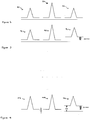
- Figure 2 is a schematic illustration of the operation of the frequency generator 50 and the correlators 52, 54, 56, as they act to track the GPS signal at low signal levels.
- three frequencies are generated locally, separated by typically 20 Hz.
- the centre one is set to be as close as possible to the anticipated Doppler frequency of the GPS satellite.
- the three correlators 52, 54, 56 then perform respective incoherent correlations between the received signal and all three of the locally generated frequencies. For each of the three frequencies, correlation is performed across 24 code taps, typically separated by a quarter chip of code phase. This gives a visibility of a range of 6 chips, corresponding to a physical distance in the order of 1800 meters. This allows the device to detect direct signals, but also reflected signals that will have a greater path length from the satellite than the direct line of sight signal.
- the receiver software attempts to maintain the peak code signal in the eighth tap of the 24 tap code array.
- Figure 2 shows, schematically, the typical outputs of these correlators.
- the output of the first correlator 52, corresponding to the lower frequency signal, is shown by the reference numeral 82
- the output of the second correlator 54, corresponding to the centre frequency signal is shown by the reference numeral 84
- the output of the third correlator 56, corresponding to the upper frequency signal is shown by the reference numeral 86.
- each of these outputs has a peak, and the timings of the signals are adjusted so that the peak appears on the eighth tap.
- the outputs of the first correlator 52 and the third correlator 56 are fed back to the frequency generator 50 as part of a frequency lock loop.
- the output of the second correlator 54 has a higher peak than either of the outputs of the first correlator 52 and the third correlator 56, reflecting the fact that the centre frequency is the closest of the three frequencies to the Doppler frequency of the received signals.
- the lower and upper frequencies are spaced equally from the centre frequency and so, when the peaks of the outputs of the first correlator 52 and the third correlator 56 are the same height (as shown in Figure 2 ), this indicates that the upper and lower frequencies are equidistant from the Doppler frequency of the received signals, and hence that the centre frequency is very close to the frequency of the received signals.
- the frequency generator 50 detects this difference, and adjusts the centre frequency so that the heights of the peaks in the correlator outputs 82, 86 remain equal. This ensures that the centre frequency remains very close to the frequency of the received signals.
- the output of the correlator 54 is then used on that basis to make pseudorange measurements in the processor 32 in a conventional manner.
- this feedback loop is unable to operate correctly if a carrier wave (CW) jamming signal is present, and is within a few tens of Hz of any of the three locally generated frequencies.
- CW carrier wave
- a jamming signal is present in the band of one of the three frequencies, it has the effect of increasing the count of each tap of the affected frequency. All 24 code taps of the associated frequency are affected to a similar degree as a pure CW jamming signal has no pseudo-random code associated with its signal.
- FIG. 3 the output of the first correlator 52, corresponding to the lower frequency signal, is shown by the reference numeral 92, the output of the second correlator 54, corresponding to the centre frequency signal, is shown by the reference numeral 94, and the output of the third correlator 56, corresponding to the upper frequency signal, is shown by the reference numeral 96.
- each of these outputs has a peak, and the timings of the signals are adjusted so that the peak appears on the eighth tap.
- the peak in the output 96 of the third correlator 56 is now higher than the peak in the output 92 in the output of the first correlator 52.
- the frequency generator 50 adjusts the three frequencies in order to equalise the heights of the peaks in these two outputs.
- the peaks of the outputs of the first correlator 52 and the third correlator 56 are the same height, but this has been achieved only by adjusting the centre frequency so that it is less close to the frequency of the received signals.
- the method according to the present invention seeks to mitigate this problem by removing at least some of the effects of a jamming signal on the correlator outputs.
- Figure 5 illustrates the relevant data flows 120.
- the correlators 52, 54, 56 Over a first detection period, namely one 20ms data period of the satellite signals, the correlators 52, 54, 56 produce correlations in the complex I, Q domain (that is, with in-phase and quadrature components) on a coherent basis. These correlation values are passed to respective magnitude detection blocks 122, 124, 126.
- the GPS signals can be heavily attenuated. Under these conditions, coherent phase lock to the GPS satellite signal is not normally possible, and tracking can typically only be achieved by incoherently correlating over a second period of time, which may be up to several seconds. At these indoor GPS signal levels, the tracking is affected by jamming signals at much lower levels. For example, performance can start to degrade once the jamming signal power exceeds a level that is more than 10 dB less than the satellite signal.
- a signal strength detection block 128 determines the strength of the received GPS signal. Based on this determination, the duration of the second, incoherent, period is determined. As mentioned above, the incoherent period can be up to several seconds when the received signal is very weak, or can in principle be equal to the first, coherent, detection period of 20ms if the signal is strong enough
- the magnitudes determined by the magnitude detection blocks 122, 124, 126 are passed to respective adders 130, 132, 134, which sum their respective inputs over the duration of the incoherent period, as determined by the strength detection block 128.
- the outputs of the adders 130, 132, 134 are passed to respective average base value calculators 136, 138, 140.
- the outputs of the adders 130, 132, 134 are the magnitudes of the outputs of the correlators 52, 54, 56, summed over the incoherent period. As such, these outputs have the general form shown in Figure 4 . It is therefore necessary to estimate the power of the jamming signal contained in each of the three frequencies of code tap arrays.
- the base value calculators 136, 138, 140 determine the count values of the respective correlator outputs, at tap values where these are not influenced by the received satellite signal. Thus, a subset of the tap values is considered. In this illustrated example, where the peak is controlled so that it appears at the eighth tap, all taps before the eighth are ignored for this purpose, because they might include the effect of reflected signals. In addition, taps within one chip period of the peak are also ignored, because they will be influenced by the received satellite signal. In this case, the taps are separated by one quarter of a chip period, and so it is only taps after the twelfth that are considered when determining the respective base values.
- Figure 4 shows the forms of the correlator outputs in a schematic, idealised form, but it will be appreciated that in practice there will be variation in the count values at different taps.
- the base value calculators 136, 138, 140 determine the count values of the respective correlator outputs, averaged across the tap values of the subset of the tap values that is being considered.
- the outputs 102, 104 are not influenced by the jamming signal, and so they each have the base value L1.
- the output 106 is influenced by the jamming signal, and so it has the higher base value L2.
- the three base values determined by the base value calculators 136, 138, 140 are passed to a minimum determining block 142, which determines the lowest of these three base values.
- a minimum determining block 142 which determines the lowest of these three base values.
- the smallest base value, L1 applies to two of the outputs.
- the three base values determined by the base value calculators 136, 138, 140 are also passed to the respective first inputs of subtractors 144, 146, 148, and the lowest value calculated by the minimum determining block 142 is passed to the respective second inputs of the subtractors 144, 146, 148.
- the result in each case, is the increase in the base level, caused by the influence of the jamming signal.
- the result of the subtraction is zero in the case of the lower and centre frequencies, but is equal to (L2 - L1) in the case of the upper frequency.
- the outputs of the subtractors 144, 146, 148 thus represent the effect of the jamming signal over the whole incoherent period, and they are passed to respective dividers 150, 152, 154.
- the purpose of the dividers 150, 152, 154 is to determine the effect of the jamming signal in each 20ms coherent detection period.
- the signal strength detection block 128, which determined the length of the incoherent period supplies a signal to an incoherent to coherent scaling block 156, which determines the ratio of the lengths of the incoherent period and the coherent period. That is, when the incoherent period is equal to the coherent period, this ratio is equal to one, while, when the incoherent period is 2s while the coherent period is 20ms, this ratio is 100.
- This ratio is passed to the dividers 150, 152, 154, and used to divide the outputs of the subtractors 144, 146, 148.
- the result of the division represents the effect of the jamming signal in each 20ms coherent detection period.
- the outputs of the dividers 150, 152, 154 are passed to respective delay units 158, 160, 162, where they are stored during the whole of the next incoherent period, and passed as inputs to respective subtractors 164, 166, 168 throughout that incoherent period.
- the other inputs of the subtractors 164, 166, 168 receive inputs from the magnitude detection blocks 122, 124, 126.
- the magnitude detection blocks produce an output value during each 20ms coherent detection period.
- the output of each divider 150, 152, 154 is subtracted from the corresponding magnitude value produced by the respective magnitude detection block 122, 124, 126 during each coherent detection period during the appropriate incoherent period.
- the jamming signal and the satellite signal are correlated in the complex I, Q domain, whereas the incoherent measurements are made in the magnitude domain.
- the jamming signal can in fact both add to, and subtract from, the satellite signal, in the coherent period. To compensate for this, it is possible to subtract only a portion of the detected jamming signal from the incoherent period during each subsequent coherent period.
- the block represented as the FLL filter 170 is a software algorithm that enables the frequency generated by the frequency generator 50 to be kept aligned with the Doppler frequency of the signal received from the satellite 28, as described above with reference to Figure 2 .
- the frequency generator 50 is able to adapt the centre frequency based on a frequency error that is indicated by the relative heights of the peaks in the correlations at the upper and lower frequencies, using correlations which have been adjusted as described here to remove the effects of the jamming signal.
- the method described in this example determines the effect of the jamming signals over the whole of an incoherent period, and then applies the results during every coherent period of the following incoherent period.
- This latency means that the method is unable to deal with the effects of rapidly varying jamming signals, for example when the unit is accelerating rapidly.
- the low level of jamming signals relative to the random noise in the signal means that jamming signals will typically not be detectable within a 20 ms interval, and so it is not always possible to determine (and hence remove) the effect of the jamming signal in each individual coherent period.
- the magnitude of the jamming signal can also calculated, allowing determination of the Jammer to Noise ratio (JNR), which can then be output for information.
- JNR Jammer to Noise ratio
- the JNR figure is calculated from the non peak correlations of all three frequencies, for example Jammer to Noise power (in dB Hz) is calculated as 6 times log (base 2) (Jammer Power / Noise Power), where the Jammer Power and Noise Power are read from the magnitude detectors 122, 124, 126, and normalized to a one second period. As all three frequencies are used, a large JNR figure could be published when the jammer is coincident with the centre frequency. For example, the calculated JNR figure can be used when estimating the degradation of the signal in the Position Engine in which the GPS signals are used.
- the received signal power When there are no obstructions between the users GPS antenna and the satellite, the received signal power will be strong, and the receiver will be able to maintain a coherent phase lock on the satellite signals. With strong GPS signals, jamming occurs only infrequently, and generally, the receivers will not be affected by jamming signals until the magnitude of the jamming signal approaches that of the GPS satellite signal.
- the use of software algorithms is thus of maximum benefit when the GPS signals are low level, i.e. less than 25 dB Hz, and jamming signals are present between this level and 10 dB below this level.
Landscapes
- Engineering & Computer Science (AREA)
- Computer Networks & Wireless Communication (AREA)
- Signal Processing (AREA)
- Radar, Positioning & Navigation (AREA)
- Remote Sensing (AREA)
- Physics & Mathematics (AREA)
- General Physics & Mathematics (AREA)
- Position Fixing By Use Of Radio Waves (AREA)
Claims (15)
- Procédé à utiliser dans un dispositif de positionnement/suivi GNSS pour la détection d'un signal et l'élimination d'un signal non souhaité depuis le signal détecté, le procédé comprenant :la détermination de première, deuxième et troisième corrélations respectives sur une pluralité d'impulsions de code entre un signal reçu et des signaux à des première, deuxième et troisième fréquences, la deuxième fréquence étant supérieure à la première fréquence et inférieure à la troisième fréquence, et étant à égale distance des première et troisième fréquences ;l'adaptation de la deuxième fréquence à une fréquence du signal reçu de telle sorte que des pics dans les première et troisième corrélations après une adaptation correspondante des première et troisième fréquences aient des amplitudes essentiellement égales ;caractérisé par :la détermination d'une différence entre une valeur de base des première et troisième corrélations ; etl'ajustement des valeurs d'au moins l'une des corrélations pour compenser les effets du signal non souhaité, en fonction de ladite différence.
- Procédé selon la revendication 1, dans lequel l'étape de détermination de la différence entre les valeurs de base des première et troisième corrélations comprend la détermination d'une différence entre des amplitudes des première et troisième corrélations à des positions d'impulsions correspondant à des signaux arrivant avant les pics respectifs.
- Procédé selon la revendication 2, dans lequel l'étape de détermination de la différence entre les valeurs de base des première et troisième corrélations comprend la détermination d'une différence entre des amplitudes moyennes des première et troisième corrélations sur une plage de positions d'impulsions correspondant à des signaux arrivant avant les pics respectifs.
- Procédé selon l'une quelconque des revendications précédentes, dans lequel les étapes de détermination de la différence entre les valeurs de base des première et troisième corrélations ; et d'ajustement des valeurs d'au moins l'une des corrélations pour compenser les effets du signal non souhaité, en fonction de ladite différence, comprennent :la détermination des valeurs de bases des première, deuxième et troisième corrélations ;la détermination d'une valeur la plus basse parmi les valeurs de base des première, deuxième et troisième corrélations ;la sélection de ladite valeur la plus basse des valeurs de base des première, deuxième et troisième corrélations à partir de chacune des valeurs de base des première, deuxième et troisième corrélations pour former des différences respectives ; etla soustraction des différence respectives à partir des amplitudes des première, deuxième et troisième corrélations.
- Procédé selon l'une quelconque des revendications précédentes, comprenant en outre :la détermination desdites première, deuxième et troisième corrélations pendant chacune d'une pluralité de premières périodes ;la détermination d'une durée pour une deuxième période, en fonction d'une intensité de signal du signal reçu, ladite deuxième période s'étendant sur au moins une première période ;la détermination de ladite différence entre les valeurs de base des première et troisième corrélations sur une deuxième période ; etl'ajustement des valeurs d'au moins l'une des corrélations pour compenser les effets du signal non souhaité, en fonction de ladite différence, pendant la ou chaque première période d'une deuxième période suivante.
- Procédé selon l'une quelconque des revendications précédentes, comprenant l'utilisation de la deuxième fréquence adaptée pour démoduler le signal pour une détection à partir du signal reçu.
- Procédé selon l'une quelconque des revendications précédentes, dans lequel le signal reçu est un signal provenant d'un système de navigation par satellite.
- Récepteur à utiliser dans un dispositif de positionnement/suivi GNSS pour la détection d'un signal et l'élimination d'un signal non souhaité depuis le signal détecté, le récepteur comprenant :au moins un corrélateur configuré pour déterminer des première, deuxième et troisième corrélations respectives sur une pluralité d'impulsions de code entre un signal reçu et des signaux à des première, deuxième et troisième fréquences, la deuxième fréquence étant supérieure à la première fréquence et inférieure à la troisième fréquence, et étant à égale distance des première et troisième fréquences ;un contrôleur configuré pour adapter la deuxième fréquence à une fréquence du signal reçu de telle sorte que des pics dans les première et troisième corrélations après une adaptation correspondante des première et troisième fréquences aient des amplitudes essentiellement égales ;caractérisé en ce que le contrôleur est configuré pour :déterminer une différence entre les valeurs de base des première et troisième corrélations ; etajuster les valeurs d'au moins l'une des corrélations pour compenser les effets du signal non souhaité, en fonction de ladite différence.
- Récepteur selon la revendication 8, dans lequel le contrôleur est configuré pour déterminer la différence entre les valeurs de base des première et troisième corrélations en déterminant une différence entre des amplitudes des première et troisième corrélations à des positions d'impulsions correspondant à des signaux arrivant avant les pics respectifs.
- Récepteur selon la revendication 9, dans lequel le contrôleur est configuré pour déterminer la différence entre les valeurs de base des première et troisième corrélations en déterminant une différence entre des amplitudes moyennes des première et troisième corrélations sur une plage de positions d'impulsions correspondant à des signaux arrivant avant les pics respectifs.
- Récepteur selon l'une quelconque des revendications 8 à 10, dans lequel le contrôleur est configuré pour déterminer la différence entre les valeurs de base des première et troisième corrélations ; et pour ajuster les valeurs d'au moins l'une des corrélations pour compenser les effets du signal non souhaité, en fonction de ladite différence, en :déterminant les valeurs de bases des première, deuxième et troisième corrélations ;déterminant une valeur la plus basse parmi les valeurs de base des première, deuxième et troisième corrélations ;sélectionnant ladite valeur la plus basse des valeurs de base des première, deuxième et troisième corrélations à partir de chacune des valeurs de base des première, deuxième et troisième corrélations pour former des différences respectives ; etsoustrayant les différence respectives à partir des amplitudes des première, deuxième et troisième corrélations.
- Récepteur selon l'une quelconque des revendications 8 à 11, dans lequel le contrôleur est en outre configuré pour :déterminer lesdites première, deuxième et troisième corrélations pendant chacune d'une pluralité de premières périodes ;déterminer une durée pour une deuxième période, en fonction d'une intensité de signal du signal reçu, ladite deuxième période s'étendant sur au moins une première période ;déterminer ladite différence entre les valeurs de base des première et troisième corrélations sur une deuxième période ; etajuster les valeurs d'au moins l'une des corrélations pour compenser les effets du signal non souhaité, en fonction de ladite différence, pendant la ou chaque première période d'une deuxième période suivante.
- Récepteur selon l'une quelconque des revendications 8 à 12, comprenant un démodulateur configuré pour démoduler le signal pour une détection à partir du signal reçu à l'aide de la deuxième fréquence adaptée.
- Récepteur pour un système de navigation par satellites selon l'une quelconque des revendications 8 à 13.
- Produit de programme informatique, comprenant un support lisible par ordinateur, contenant des instructions, configuré pour mettre en oeuvre un procédé selon l'une quelconque des revendications 1 à 7 lorsqu'il est exécuté sur un ordinateur.
Priority Applications (4)
| Application Number | Priority Date | Filing Date | Title |
|---|---|---|---|
| EP12173796.9A EP2680036B1 (fr) | 2012-06-27 | 2012-06-27 | Détection de signaux en présence d'un signal de brouillage |
| PCT/EP2013/063257 WO2014001323A1 (fr) | 2012-06-27 | 2013-06-25 | Détection d'un signal en présence d'un signal brouilleur |
| US14/405,475 US9467247B2 (en) | 2012-06-27 | 2013-06-25 | Signal detection in the presence of a jamming signal |
| IN10816DEN2014 IN2014DN10816A (fr) | 2012-06-27 | 2014-12-17 |
Applications Claiming Priority (1)
| Application Number | Priority Date | Filing Date | Title |
|---|---|---|---|
| EP12173796.9A EP2680036B1 (fr) | 2012-06-27 | 2012-06-27 | Détection de signaux en présence d'un signal de brouillage |
Publications (2)
| Publication Number | Publication Date |
|---|---|
| EP2680036A1 EP2680036A1 (fr) | 2014-01-01 |
| EP2680036B1 true EP2680036B1 (fr) | 2017-08-02 |
Family
ID=46384231
Family Applications (1)
| Application Number | Title | Priority Date | Filing Date |
|---|---|---|---|
| EP12173796.9A Not-in-force EP2680036B1 (fr) | 2012-06-27 | 2012-06-27 | Détection de signaux en présence d'un signal de brouillage |
Country Status (4)
| Country | Link |
|---|---|
| US (1) | US9467247B2 (fr) |
| EP (1) | EP2680036B1 (fr) |
| IN (1) | IN2014DN10816A (fr) |
| WO (1) | WO2014001323A1 (fr) |
Families Citing this family (2)
| Publication number | Priority date | Publication date | Assignee | Title |
|---|---|---|---|---|
| GB201401237D0 (en) | 2014-01-24 | 2014-03-12 | Qinetiq Ltd | Improvements to satellite positioning methods |
| CN119727943B (zh) * | 2024-11-01 | 2025-10-21 | 北京理工大学 | 基于干扰删除相关峰差分的多用户非正交信号捕获方法 |
Family Cites Families (5)
| Publication number | Priority date | Publication date | Assignee | Title |
|---|---|---|---|---|
| US6642884B2 (en) * | 2000-05-08 | 2003-11-04 | Sigtec Navigation Pty Ltd. | Satellite-based positioning system receiver for weak signal operation |
| JP2006502412A (ja) * | 2002-10-04 | 2006-01-19 | シグテック・ナヴィゲーション・プロプライエタリー・リミテッド | 衛星利用測位システムの改良 |
| US8170085B2 (en) * | 2006-03-09 | 2012-05-01 | CSR Technology Holdings Inc. | Multipath error estimation in satellite navigation receivers |
| GB0615930D0 (en) * | 2006-08-10 | 2006-09-20 | Univ Surrey | A receiver of binary offset carrier modulated signals |
| EP1916535B1 (fr) * | 2006-10-26 | 2015-11-18 | Qualcomm Incorporated | Suppression de la corrélation croisée dans un récepteur GNSS |
-
2012
- 2012-06-27 EP EP12173796.9A patent/EP2680036B1/fr not_active Not-in-force
-
2013
- 2013-06-25 US US14/405,475 patent/US9467247B2/en not_active Expired - Fee Related
- 2013-06-25 WO PCT/EP2013/063257 patent/WO2014001323A1/fr not_active Ceased
-
2014
- 2014-12-17 IN IN10816DEN2014 patent/IN2014DN10816A/en unknown
Non-Patent Citations (1)
| Title |
|---|
| None * |
Also Published As
| Publication number | Publication date |
|---|---|
| EP2680036A1 (fr) | 2014-01-01 |
| IN2014DN10816A (fr) | 2015-09-04 |
| WO2014001323A1 (fr) | 2014-01-03 |
| US20150163012A1 (en) | 2015-06-11 |
| US9467247B2 (en) | 2016-10-11 |
Similar Documents
| Publication | Publication Date | Title |
|---|---|---|
| US11740362B2 (en) | Receiver-independent spoofing detection device | |
| US6868110B2 (en) | Multipath and tracking error reduction method for spread-spectrum receivers | |
| CN100384104C (zh) | 在gps信号捕获中的振荡器频率校正 | |
| US8125381B2 (en) | Satellite-based positioning system improvement | |
| US20120201278A1 (en) | Cross-talk mitigation in global navigation satellite systems | |
| US6879913B1 (en) | Indoor GPS clock | |
| JP2003518819A (ja) | 強信号をキャンセルして弱スペクトラム拡散信号を強める方法 | |
| EP1173778A1 (fr) | Detecteur de signaux recourant a l'analyse par correlation de segments d'echantillons non uniformes et disjoints | |
| US20090153397A1 (en) | Gnss satellite signal interference handling method and correlator implementing the same | |
| US7903026B2 (en) | Positioning apparatus and positioning apparatus control method | |
| KR20170000806A (ko) | 다중 경로 환경의 위성 신호 트래킹 장치 | |
| EP1288672A1 (fr) | Procédé et dispositif pour le traitement des signaux pour la mesure de distance | |
| US12481071B2 (en) | GNSS spoofing detection and mitigation using peak suppression monitor | |
| US9467247B2 (en) | Signal detection in the presence of a jamming signal | |
| JP5029190B2 (ja) | 受信回路、電子機器及びノイズキャンセル方法 | |
| US20050147191A1 (en) | Extended frequency error correction in a wireless communication receiver | |
| US8908744B1 (en) | Discriminator system for timing error detection in presence and absence of multipath conditions | |
| US8175136B2 (en) | Noise cancellation method, receiver circuit, and electronic instrument | |
| Deshpande | Study of interference effects on GPS signal acquisition | |
| Bolla et al. | Joint Tracking of Multiple Frequency Signals from the same GNSS satellite | |
| EP2140562B1 (fr) | Procédés, dispositifs et produits-programmes informatiques pour une corrélation de codes de signaux à étalement de spectre multitrajet | |
| US9236903B2 (en) | Multi-path detection | |
| Mubarak et al. | Performance comparison of ELP and DELP for multipath detection | |
| US7230999B1 (en) | Method for extended coherent data demodulation for GPS receivers | |
| Jansen | The impact of jamming and spoofing on GNSS signals |
Legal Events
| Date | Code | Title | Description |
|---|---|---|---|
| PUAI | Public reference made under article 153(3) epc to a published international application that has entered the european phase |
Free format text: ORIGINAL CODE: 0009012 |
|
| AK | Designated contracting states |
Kind code of ref document: A1 Designated state(s): AL AT BE BG CH CY CZ DE DK EE ES FI FR GB GR HR HU IE IS IT LI LT LU LV MC MK MT NL NO PL PT RO RS SE SI SK SM TR |
|
| AX | Request for extension of the european patent |
Extension state: BA ME |
|
| 17P | Request for examination filed |
Effective date: 20140529 |
|
| RBV | Designated contracting states (corrected) |
Designated state(s): AL AT BE BG CH CY CZ DE DK EE ES FI FR GB GR HR HU IE IS IT LI LT LU LV MC MK MT NL NO PL PT RO RS SE SI SK SM TR |
|
| RIC1 | Information provided on ipc code assigned before grant |
Ipc: G01S 19/21 20100101AFI20161221BHEP Ipc: H04B 1/16 20060101ALN20161221BHEP Ipc: H04K 3/00 20060101ALN20161221BHEP |
|
| GRAP | Despatch of communication of intention to grant a patent |
Free format text: ORIGINAL CODE: EPIDOSNIGR1 |
|
| GRAJ | Information related to disapproval of communication of intention to grant by the applicant or resumption of examination proceedings by the epo deleted |
Free format text: ORIGINAL CODE: EPIDOSDIGR1 |
|
| GRAP | Despatch of communication of intention to grant a patent |
Free format text: ORIGINAL CODE: EPIDOSNIGR1 |
|
| RIC1 | Information provided on ipc code assigned before grant |
Ipc: G01S 19/21 20100101AFI20170117BHEP Ipc: H04B 1/16 20060101ALN20170117BHEP Ipc: H04K 3/00 20060101ALN20170117BHEP |
|
| INTG | Intention to grant announced |
Effective date: 20170130 |
|
| INTG | Intention to grant announced |
Effective date: 20170208 |
|
| GRAS | Grant fee paid |
Free format text: ORIGINAL CODE: EPIDOSNIGR3 |
|
| GRAA | (expected) grant |
Free format text: ORIGINAL CODE: 0009210 |
|
| AK | Designated contracting states |
Kind code of ref document: B1 Designated state(s): AL AT BE BG CH CY CZ DE DK EE ES FI FR GB GR HR HU IE IS IT LI LT LU LV MC MK MT NL NO PL PT RO RS SE SI SK SM TR |
|
| REG | Reference to a national code |
Ref country code: CH Ref legal event code: EP Ref country code: AT Ref legal event code: REF Ref document number: 915076 Country of ref document: AT Kind code of ref document: T Effective date: 20170815 |
|
| REG | Reference to a national code |
Ref country code: IE Ref legal event code: FG4D |
|
| REG | Reference to a national code |
Ref country code: DE Ref legal event code: R096 Ref document number: 602012035233 Country of ref document: DE |
|
| REG | Reference to a national code |
Ref country code: DE Ref legal event code: R082 Ref document number: 602012035233 Country of ref document: DE Representative=s name: GRUENECKER PATENT- UND RECHTSANWAELTE PARTG MB, DE Ref country code: DE Ref legal event code: R081 Ref document number: 602012035233 Country of ref document: DE Owner name: OCT CIRCUIT TECHNOLOGIES INTERNATIONAL LTD., IE Free format text: FORMER OWNER: ST-ERICSSON SA, PLAN-LES-OUATES, CH |
|
| REG | Reference to a national code |
Ref country code: NL Ref legal event code: MP Effective date: 20170802 |
|
| REG | Reference to a national code |
Ref country code: AT Ref legal event code: MK05 Ref document number: 915076 Country of ref document: AT Kind code of ref document: T Effective date: 20170802 |
|
| REG | Reference to a national code |
Ref country code: LT Ref legal event code: MG4D |
|
| PG25 | Lapsed in a contracting state [announced via postgrant information from national office to epo] |
Ref country code: SE Free format text: LAPSE BECAUSE OF FAILURE TO SUBMIT A TRANSLATION OF THE DESCRIPTION OR TO PAY THE FEE WITHIN THE PRESCRIBED TIME-LIMIT Effective date: 20170802 Ref country code: NL Free format text: LAPSE BECAUSE OF FAILURE TO SUBMIT A TRANSLATION OF THE DESCRIPTION OR TO PAY THE FEE WITHIN THE PRESCRIBED TIME-LIMIT Effective date: 20170802 Ref country code: FI Free format text: LAPSE BECAUSE OF FAILURE TO SUBMIT A TRANSLATION OF THE DESCRIPTION OR TO PAY THE FEE WITHIN THE PRESCRIBED TIME-LIMIT Effective date: 20170802 Ref country code: AT Free format text: LAPSE BECAUSE OF FAILURE TO SUBMIT A TRANSLATION OF THE DESCRIPTION OR TO PAY THE FEE WITHIN THE PRESCRIBED TIME-LIMIT Effective date: 20170802 Ref country code: LT Free format text: LAPSE BECAUSE OF FAILURE TO SUBMIT A TRANSLATION OF THE DESCRIPTION OR TO PAY THE FEE WITHIN THE PRESCRIBED TIME-LIMIT Effective date: 20170802 Ref country code: HR Free format text: LAPSE BECAUSE OF FAILURE TO SUBMIT A TRANSLATION OF THE DESCRIPTION OR TO PAY THE FEE WITHIN THE PRESCRIBED TIME-LIMIT Effective date: 20170802 Ref country code: NO Free format text: LAPSE BECAUSE OF FAILURE TO SUBMIT A TRANSLATION OF THE DESCRIPTION OR TO PAY THE FEE WITHIN THE PRESCRIBED TIME-LIMIT Effective date: 20171102 |
|
| PG25 | Lapsed in a contracting state [announced via postgrant information from national office to epo] |
Ref country code: PL Free format text: LAPSE BECAUSE OF FAILURE TO SUBMIT A TRANSLATION OF THE DESCRIPTION OR TO PAY THE FEE WITHIN THE PRESCRIBED TIME-LIMIT Effective date: 20170802 Ref country code: GR Free format text: LAPSE BECAUSE OF FAILURE TO SUBMIT A TRANSLATION OF THE DESCRIPTION OR TO PAY THE FEE WITHIN THE PRESCRIBED TIME-LIMIT Effective date: 20171103 Ref country code: LV Free format text: LAPSE BECAUSE OF FAILURE TO SUBMIT A TRANSLATION OF THE DESCRIPTION OR TO PAY THE FEE WITHIN THE PRESCRIBED TIME-LIMIT Effective date: 20170802 Ref country code: IS Free format text: LAPSE BECAUSE OF FAILURE TO SUBMIT A TRANSLATION OF THE DESCRIPTION OR TO PAY THE FEE WITHIN THE PRESCRIBED TIME-LIMIT Effective date: 20171202 Ref country code: BG Free format text: LAPSE BECAUSE OF FAILURE TO SUBMIT A TRANSLATION OF THE DESCRIPTION OR TO PAY THE FEE WITHIN THE PRESCRIBED TIME-LIMIT Effective date: 20171102 Ref country code: RS Free format text: LAPSE BECAUSE OF FAILURE TO SUBMIT A TRANSLATION OF THE DESCRIPTION OR TO PAY THE FEE WITHIN THE PRESCRIBED TIME-LIMIT Effective date: 20170802 Ref country code: ES Free format text: LAPSE BECAUSE OF FAILURE TO SUBMIT A TRANSLATION OF THE DESCRIPTION OR TO PAY THE FEE WITHIN THE PRESCRIBED TIME-LIMIT Effective date: 20170802 |
|
| PG25 | Lapsed in a contracting state [announced via postgrant information from national office to epo] |
Ref country code: DK Free format text: LAPSE BECAUSE OF FAILURE TO SUBMIT A TRANSLATION OF THE DESCRIPTION OR TO PAY THE FEE WITHIN THE PRESCRIBED TIME-LIMIT Effective date: 20170802 Ref country code: CZ Free format text: LAPSE BECAUSE OF FAILURE TO SUBMIT A TRANSLATION OF THE DESCRIPTION OR TO PAY THE FEE WITHIN THE PRESCRIBED TIME-LIMIT Effective date: 20170802 Ref country code: RO Free format text: LAPSE BECAUSE OF FAILURE TO SUBMIT A TRANSLATION OF THE DESCRIPTION OR TO PAY THE FEE WITHIN THE PRESCRIBED TIME-LIMIT Effective date: 20170802 |
|
| REG | Reference to a national code |
Ref country code: DE Ref legal event code: R097 Ref document number: 602012035233 Country of ref document: DE |
|
| PG25 | Lapsed in a contracting state [announced via postgrant information from national office to epo] |
Ref country code: SK Free format text: LAPSE BECAUSE OF FAILURE TO SUBMIT A TRANSLATION OF THE DESCRIPTION OR TO PAY THE FEE WITHIN THE PRESCRIBED TIME-LIMIT Effective date: 20170802 Ref country code: EE Free format text: LAPSE BECAUSE OF FAILURE TO SUBMIT A TRANSLATION OF THE DESCRIPTION OR TO PAY THE FEE WITHIN THE PRESCRIBED TIME-LIMIT Effective date: 20170802 Ref country code: SM Free format text: LAPSE BECAUSE OF FAILURE TO SUBMIT A TRANSLATION OF THE DESCRIPTION OR TO PAY THE FEE WITHIN THE PRESCRIBED TIME-LIMIT Effective date: 20170802 Ref country code: IT Free format text: LAPSE BECAUSE OF FAILURE TO SUBMIT A TRANSLATION OF THE DESCRIPTION OR TO PAY THE FEE WITHIN THE PRESCRIBED TIME-LIMIT Effective date: 20170802 |
|
| PLBE | No opposition filed within time limit |
Free format text: ORIGINAL CODE: 0009261 |
|
| STAA | Information on the status of an ep patent application or granted ep patent |
Free format text: STATUS: NO OPPOSITION FILED WITHIN TIME LIMIT |
|
| 26N | No opposition filed |
Effective date: 20180503 |
|
| PG25 | Lapsed in a contracting state [announced via postgrant information from national office to epo] |
Ref country code: SI Free format text: LAPSE BECAUSE OF FAILURE TO SUBMIT A TRANSLATION OF THE DESCRIPTION OR TO PAY THE FEE WITHIN THE PRESCRIBED TIME-LIMIT Effective date: 20170802 |
|
| REG | Reference to a national code |
Ref country code: CH Ref legal event code: PL |
|
| REG | Reference to a national code |
Ref country code: BE Ref legal event code: MM Effective date: 20180630 |
|
| PG25 | Lapsed in a contracting state [announced via postgrant information from national office to epo] |
Ref country code: MC Free format text: LAPSE BECAUSE OF FAILURE TO SUBMIT A TRANSLATION OF THE DESCRIPTION OR TO PAY THE FEE WITHIN THE PRESCRIBED TIME-LIMIT Effective date: 20170802 Ref country code: LU Free format text: LAPSE BECAUSE OF NON-PAYMENT OF DUE FEES Effective date: 20180627 |
|
| REG | Reference to a national code |
Ref country code: IE Ref legal event code: MM4A |
|
| PG25 | Lapsed in a contracting state [announced via postgrant information from national office to epo] |
Ref country code: IE Free format text: LAPSE BECAUSE OF NON-PAYMENT OF DUE FEES Effective date: 20180627 Ref country code: CH Free format text: LAPSE BECAUSE OF NON-PAYMENT OF DUE FEES Effective date: 20180630 Ref country code: LI Free format text: LAPSE BECAUSE OF NON-PAYMENT OF DUE FEES Effective date: 20180630 |
|
| PG25 | Lapsed in a contracting state [announced via postgrant information from national office to epo] |
Ref country code: BE Free format text: LAPSE BECAUSE OF NON-PAYMENT OF DUE FEES Effective date: 20180630 |
|
| PG25 | Lapsed in a contracting state [announced via postgrant information from national office to epo] |
Ref country code: MT Free format text: LAPSE BECAUSE OF NON-PAYMENT OF DUE FEES Effective date: 20180627 |
|
| PG25 | Lapsed in a contracting state [announced via postgrant information from national office to epo] |
Ref country code: TR Free format text: LAPSE BECAUSE OF FAILURE TO SUBMIT A TRANSLATION OF THE DESCRIPTION OR TO PAY THE FEE WITHIN THE PRESCRIBED TIME-LIMIT Effective date: 20170802 |
|
| PG25 | Lapsed in a contracting state [announced via postgrant information from national office to epo] |
Ref country code: HU Free format text: LAPSE BECAUSE OF FAILURE TO SUBMIT A TRANSLATION OF THE DESCRIPTION OR TO PAY THE FEE WITHIN THE PRESCRIBED TIME-LIMIT; INVALID AB INITIO Effective date: 20120627 Ref country code: PT Free format text: LAPSE BECAUSE OF FAILURE TO SUBMIT A TRANSLATION OF THE DESCRIPTION OR TO PAY THE FEE WITHIN THE PRESCRIBED TIME-LIMIT Effective date: 20170802 |
|
| PG25 | Lapsed in a contracting state [announced via postgrant information from national office to epo] |
Ref country code: MK Free format text: LAPSE BECAUSE OF NON-PAYMENT OF DUE FEES Effective date: 20170802 Ref country code: CY Free format text: LAPSE BECAUSE OF FAILURE TO SUBMIT A TRANSLATION OF THE DESCRIPTION OR TO PAY THE FEE WITHIN THE PRESCRIBED TIME-LIMIT Effective date: 20170802 |
|
| PG25 | Lapsed in a contracting state [announced via postgrant information from national office to epo] |
Ref country code: AL Free format text: LAPSE BECAUSE OF FAILURE TO SUBMIT A TRANSLATION OF THE DESCRIPTION OR TO PAY THE FEE WITHIN THE PRESCRIBED TIME-LIMIT Effective date: 20170802 |
|
| REG | Reference to a national code |
Ref country code: GB Ref legal event code: 732E Free format text: REGISTERED BETWEEN 20210805 AND 20210811 |
|
| PGFP | Annual fee paid to national office [announced via postgrant information from national office to epo] |
Ref country code: GB Payment date: 20220628 Year of fee payment: 11 |
|
| PGFP | Annual fee paid to national office [announced via postgrant information from national office to epo] |
Ref country code: FR Payment date: 20220627 Year of fee payment: 11 |
|
| PGFP | Annual fee paid to national office [announced via postgrant information from national office to epo] |
Ref country code: DE Payment date: 20220629 Year of fee payment: 11 |
|
| REG | Reference to a national code |
Ref country code: DE Ref legal event code: R119 Ref document number: 602012035233 Country of ref document: DE |
|
| GBPC | Gb: european patent ceased through non-payment of renewal fee |
Effective date: 20230627 |
|
| PG25 | Lapsed in a contracting state [announced via postgrant information from national office to epo] |
Ref country code: DE Free format text: LAPSE BECAUSE OF NON-PAYMENT OF DUE FEES Effective date: 20240103 Ref country code: GB Free format text: LAPSE BECAUSE OF NON-PAYMENT OF DUE FEES Effective date: 20230627 |
|
| PG25 | Lapsed in a contracting state [announced via postgrant information from national office to epo] |
Ref country code: FR Free format text: LAPSE BECAUSE OF NON-PAYMENT OF DUE FEES Effective date: 20230630 |