EP2680042B1 - Configuration d'instruments de surface pour une opération d'appareil de forage - Google Patents
Configuration d'instruments de surface pour une opération d'appareil de forage Download PDFInfo
- Publication number
- EP2680042B1 EP2680042B1 EP13186045.4A EP13186045A EP2680042B1 EP 2680042 B1 EP2680042 B1 EP 2680042B1 EP 13186045 A EP13186045 A EP 13186045A EP 2680042 B1 EP2680042 B1 EP 2680042B1
- Authority
- EP
- European Patent Office
- Prior art keywords
- pack
- receiver
- tubing
- acoustic
- transmitter
- Prior art date
- Legal status (The legal status is an assumption and is not a legal conclusion. Google has not performed a legal analysis and makes no representation as to the accuracy of the status listed.)
- Ceased
Links
Images


Classifications
-
- E—FIXED CONSTRUCTIONS
- E21—EARTH OR ROCK DRILLING; MINING
- E21B—EARTH OR ROCK DRILLING; OBTAINING OIL, GAS, WATER, SOLUBLE OR MELTABLE MATERIALS OR A SLURRY OF MINERALS FROM WELLS
- E21B47/00—Survey of boreholes or wells
- E21B47/12—Means for transmitting measuring-signals or control signals from the well to the surface, or from the surface to the well, e.g. for logging while drilling
- E21B47/14—Means for transmitting measuring-signals or control signals from the well to the surface, or from the surface to the well, e.g. for logging while drilling using acoustic waves
-
- G—PHYSICS
- G01—MEASURING; TESTING
- G01V—GEOPHYSICS; GRAVITATIONAL MEASUREMENTS; DETECTING MASSES OR OBJECTS; TAGS
- G01V1/00—Seismology; Seismic or acoustic prospecting or detecting
- G01V1/40—Seismology; Seismic or acoustic prospecting or detecting specially adapted for well-logging
- G01V1/52—Structural details
-
- E—FIXED CONSTRUCTIONS
- E21—EARTH OR ROCK DRILLING; MINING
- E21B—EARTH OR ROCK DRILLING; OBTAINING OIL, GAS, WATER, SOLUBLE OR MELTABLE MATERIALS OR A SLURRY OF MINERALS FROM WELLS
- E21B33/00—Sealing or packing boreholes or wells
- E21B33/02—Surface sealing or packing
-
- E—FIXED CONSTRUCTIONS
- E21—EARTH OR ROCK DRILLING; MINING
- E21B—EARTH OR ROCK DRILLING; OBTAINING OIL, GAS, WATER, SOLUBLE OR MELTABLE MATERIALS OR A SLURRY OF MINERALS FROM WELLS
- E21B47/00—Survey of boreholes or wells
- E21B47/12—Means for transmitting measuring-signals or control signals from the well to the surface, or from the surface to the well, e.g. for logging while drilling
- E21B47/14—Means for transmitting measuring-signals or control signals from the well to the surface, or from the surface to the well, e.g. for logging while drilling using acoustic waves
- E21B47/16—Means for transmitting measuring-signals or control signals from the well to the surface, or from the surface to the well, e.g. for logging while drilling using acoustic waves through the drill string or casing, e.g. by torsional acoustic waves
Definitions
- the application relates generally to communications.
- the application relates to acoustic communications for drilling rig-related operations.
- Measurement of parameters such as weight on bit, torque, wear and bearing condition in real time provides for more efficient drilling operations. In fact, faster penetration rates, better trip planning, reduced equipment failures, fewer delays for directional surveys, and the elimination of a need to interrupt drilling for abnormal pressure detection is achievable using MWD techniques.
- One current approach to provide real time data from the vicinity of the drill bit to the surface includes acoustic communications.
- an acoustic signal is generated near the bit and is transmitted through the drill pipe, mud column or the earth. It has been found, however, that the very low intensity of the signal which can be generated downhole, along with the acoustic noise generated by the drilling system, makes signal detection difficult.
- Reflective and refractive interference resulting from changing diameters and thread makeup at the tool joints compounds the signal attenuation problem for drill pipe transmission. Such reflective and refractive interference causes interbit interference among the bits of data being transmitted.
- Acoustic communications are further complicated when surface slips are used on the drill rig floor.
- surface slips may be used to provide support during periods when drill stand is being added or removed to the drill pipe.
- additional drill pipe may be periodically installed to increase the depth of such drill pipe downhole or remove as part of a tripping operation.
- the surface slips generally surround an opening in the rig floor through which the upper end of the uppermost joint of drill pipe protrudes. The surface slips hold the protruded drill pipe in position (a few feet above the surface of the rig floor) to allow rig personnel and/or automated handling equipment to attach or remove drill pipe.
- the surface slips may act as a reflective point for the acoustic communications between downhole and surface instrumentation, thereby distorting and/or damping such communications.
- US 2004/047534 A1 discloses a system in which a portion of at least one fiber is moved into an exterior annulus of a well between a tubular structure in the well and the wall of the borehole of the well such that the portion is placed to conduct a signal responsive to at least one parameter in the exterior annulus.
- One particular implementation uses fiber optic cable with a cementing process whereby flowing cementing fluid pulls the portion of the cable into the exterior annulus.
- the present invention provides an apparatus as set out in appended claim 1.
- the present invention provides a method as set out in appended claim 8 Preferred embodiments of the invention may be gathered from the dependent claims.
- embodiments may be used any other types of environments for acoustic communications. Additionally, some embodiments of the invention may be applicable during both Logging While Drilling (LWD) and Measurement While Drilling (MWD) operations while the drill pipe is stationary. Some embodiments may be performed during a logging while tripping operation, zero emissions testing, drill stem testing, etc. Additionally, some embodiments are applicable not only during drilling, but throughout the life of a wellbore including, but not limited to, during logging, drill stem testing, completing and production.
- LWD Logging While Drilling
- MWD Measurement While Drilling
- Some embodiments may be performed during a logging while tripping operation, zero emissions testing, drill stem testing, etc. Additionally, some embodiments are applicable not only during drilling, but throughout the life of a wellbore including, but not limited to, during logging, drill stem testing, completing and production.
- some examples not part of the invention may include one or more instrumented surface slips.
- surface slip(s) which typically provide support to the drill pipe during various phases of the drilling rig-related operations, may include a communications receiver and/or transmitter.
- the surface slip(s) may include an acoustic receiver (such as an accelerometer) positioned approximately at or near its bottom end.
- the surface slip(s) may include an acoustic transmitter to transmit data communications to downhole instrumentation. Accordingly, as described, examples not part of the invention enable high-speed telemetry operations along the drill pipe while the drill pipe is in the surface slips.
- examples not part of the invention may allow for acoustic communications essentially independent of interference by the surface slip(s).
- embodiments allow a rig crew to install and uninstall instrumentation as part of normal rig procedures to change a pipe stand. Further, some embodiments may incorporate instrumentation into other surface equipment. According to the invention, such instrumentation is incorporated into pack-off material.
- FIG. 1 illustrates a system for drilling operations, according to some embodiments of the invention.
- a system 100 includes a drilling rig 102 located at a surface 104 of a well.
- the drilling rig 102 provides support for a drill string 108.
- the drill string 108 penetrates a rotary table 110 for drilling a borehole 112 through subsurface formations 114.
- the drill string 108 includes a Kelly 116 (in the upper portion), a drill pipe 118 and a bottom hole assembly 120 (located at the lower portion of the drill pipe 118).
- the bottom hole assembly 120 may include a drill collar 122, a downhole tool 124 and a drill bit 126.
- the downhole tool 124 may be any of a number of different types of tools including Measurement While Drilling (MWD) tools, Logging While Drilling (LWD) tools, etc.
- MWD Measurement While Drilling
- LWD Logging While Drilling
- the drill string 108 (including the Kelly 116, the drill pipe 118 and the bottom hole assembly 120) may be rotated by the rotary table 110.
- the bottom hole assembly 120 may also be rotated by a motor (not shown) that is downhole.
- the drill collar 122 may be used to add weight to the drill bit 126.
- the drill collar 122 also may stiffen the bottom hole assembly 120 to allow the bottom hole assembly 120 to transfer the weight to the drill bit 126. Accordingly, this weight provided by the drill collar 122 also assists the drill bit 126 in the penetration of the surface 104 and the subsurface formations 114.
- a mud pump 132 may pump drilling fluid (known as "drilling mud") from a mud pit 134 through a hose 136 into the drill pipe 118 down to the drill bit 126.
- the drilling fluid can flow out from the drill bit 126 and return back to the surface through an annular area 140 between the drill pipe 118 and the sides of the borehole 112.
- the drilling fluid may then be returned to the mud pit 134, where such fluid is filtered. Accordingly, the drilling fluid can cool the drill bit 126 as well as provide for lubrication of the drill bit 126 during the drilling operation. Additionally, the drilling fluid removes the cuttings of the subsurface formations 114 created by the drill bit 126.
- the drill string 108 may include one to a number of different sensors 151, which monitor different downhole parameters. Such parameters may include the downhole temperature and pressure, the various characteristics of the subsurface formations (such as resistivity, density, porosity, etc.), the characteristics of the borehole (e.g., size, shape, etc.), etc.
- the drill string 108 may also include an acoustic transmitter 123 that transmits telemetry signals in the form of acoustic vibrations in the tubing wall of the drill sting 108.
- An acoustic receiver 115 is coupled to the kelly 116 to receive transmitted telemetry signals.
- One or more repeaters 119 may be provided along the drill string 108 to receive and retransmit the telemetry signals.
- the repeaters 119 may include both an acoustic telemetry receiver and an acoustic telemetry transmitter configured similarly to the acoustic receiver 115 and the acoustic transmitter 123.
- Figures 2-6 illustrate different configurations for surface slips and pack-off material having surface receivers and/or surface transmitters, according to some embodiments of the invention.
- Figure 2 illustrates surface slips having a surface receiver and a surface transmitter, according to some examples not part of the invention.
- Figure 2 illustrates a tubing 202 positioned in a borehole 217.
- the tubing 202 may be a drill string (such as the drill string 108 shown in Figure 1 ), a wired pipe, a production tubing, etc.
- the borehole 217 includes sides 215, which may include casing.
- An annulus 214 is formed between the tubing 202 and the sides 215.
- Surface slips 204A-204B are positioned within the annulus 214 at the rig floor 210.
- the surface slips 204A-204B may include gripping elements adjacent to the tubing 202 used to attach the surface slips 204A-204B to the tubing 202.
- the surface slips 204A-204B may be manual or hydraulic.
- the surface slips 204A-204B may provide support to the tubing 202.
- the surface slips 204A-204B may be inserted along the tubing 202 when a pipe stand is being added or removed there from.
- the tubing 202 may include a joint 219, which may be the location where a pipe stand is added or removed.
- the surface slips 204A-204B may include instrumentation.
- the instrumentation may include a surface receiver 212 and surface transmitters 206A-206B.
- the surface receiver 212 may be positioned at or near the top of the surface slips 204A-204B for simplicity of implementation. However, if the surface receiver 212 is positioned near the top or above the surface slips 204A-204B, the surface receiver 212 may receive acoustic signals that have undergone significant dissipation in the rig floor. In some embodiments, the surface receiver 212 may be positioned at or near the bottom end of the surface slips 204A-204B, thereby positioning the surface receiver 212 below the rig floor.
- the surface receiver 212 may receive the acoustic signals from downhole before such signals may be subject to dissipation. This position of the surface receiver 212 may increase the signal to noise ratio of the received acoustic signal, thereby potentially increasing the data bandwidth.
- the surface receiver 212 may be positioned approximately at or near the bottom end of the surface slip 204A, relative to its position in the borehole 217.
- the surface transmitter 206A and the surface transmitter 206B are respectively positioned approximately at or near the top end of the surface slip 204A and the top end of the surface slip 204B, relative to their positions in the borehole 217.
- the surface receiver 212 may be a number of different types of acoustic receivers including an accelerometer, a strain gage, etc.
- the surface receiver 212 and/or the surface transmitters 206A-206B may be attached (bolted, welded, etc.) to the surface slips 206A-206B. In some embodiments, the surface receiver 212 and/or the surface transmitters 206A-206B may be manufactured as a single object.
- the surface slip 206A may include a signal line 208.
- the signal line 208 may provide a power signal to the surface transmitter 206A and/or the surface receiver 212.
- the signal line 208 may provide a communications signal (such as data communications) to and from the surface transmitter 206A and/or the surface receiver 212.
- the surface slips 206A-206B may be without the signal line 208 (as shown by surface slip 206B).
- a power source such as a battery
- communications with the surface transmitters 206A-206B and/or the surface receiver 212 may be through wireless communications or other wired coupling (not shown).
- the surface receiver 212 may include a storage medium to store data communications received from downhole. Such data may be downloaded there from subsequent to the removal of the surface slips 204A-204B from their support of the tubing 202.
- some embodiments include an acoustic surface receiver positioned below the surface slips 206 to receive acoustic communications from downhole. Such positioning allows for acoustic communications along the tubing that is essentially independent of interference (such as reflections) caused by the surface slips 206.
- Figure 3 illustrates surface slips having a surface receiver and a surface transmitter, according to some examples not part of the invention.
- Figure 3 illustrates a configuration of the surface slips wherein both the surface receiver and the surface transmitter are positioned approximately at or near the bottom end of the surface slips.
- the surface slips 204A-204B may include instrumentation. Similar to the configuration shown in Figure 2 , the instrumentation may include the surface receiver 212 and the surface transmitters 206A-206B.
- the surface transmitter 206A and the surface transmitter 206B are respectively positioned approximately at or near the bottom end of the surface slip 204A and the bottom end of the surface slip 204B, relative to their positions in the borehole 217.
- the surface receiver 212 is positioned approximately near or below the bottom end of the surface transmitter 206A, relative to its position in the borehole 217.
- the surface receiver 212 is a given distance from the gripping elements of the surface slip 204A used to attached the surface slip 204A to the tubing 202.
- such distance may be dependent on the wavelength of the acoustic signal being transmitted from downhole to be received by the surface receiver 212. In particular, this distance may be set to avoid null points caused by the reflections by the surface slip 204A.
- the surface receiver 212 may be approximately ⁇ /16 and 3 ⁇ /8 from the gripping elements of the surface slip 204A.
- Figure 4 illustrates a surface slip having a surface receiver, according to some examples not part of the invention.
- Figure 4 illustrates a configuration wherein a surface slip only includes a surface receiver positioned approximately at or near the bottom end of the surface slip.
- the surface slip 204A may include the surface receiver 212.
- the surface receiver 212 is positioned approximately at or near the bottom end of the surface slip 204A, relative to its position in the borehole 217.
- Figure 5 illustrates a surface slip having a surface receiver, according to some examples not part of the invention.
- Figure 4 illustrates a configuration wherein a surface receiver may be positioned at a location that is not approximately at or near the bottom end of the surface slip.
- the surface slip 204A may include the surface receiver 212.
- the surface receiver 212 is positioned within the surface slip 204A (and not a given end of the surface slip 204A).
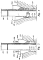
- Figure 6 illustrates pack-off material having a surface receiver and a surface transmitter, according to some embodiments of the invention.
- Figure 6 illustrates a pack-off material 602A-602B that is used to plug the borehole around the tubing 202.
- the pack-off material 602A-602B may be positioned around the tubing 202 to maintain the pressure downhole.
- the pack-off material 602A-602B includes instrumentation.
- the instrumentation may include a surface receiver 606 and a surface transmitter 604.
- the surface receiver 606 may be positioned approximately at or near the bottom end of the pack-off material 602A, relative to its position in the borehole 217.
- the surface transmitter 604 may be positioned approximately at or near the bottom end of the pack-off material 602B, relative to its position in the borehole 217.
- the surface receiver 606 may be a number of different types of acoustic receivers including an accelerometer, a strain gage, etc.
- the surface receiver 606 and/or the surface transmitter 604 may be embedded or attached (e.g., using an adhesive, etc.) to the pack-off material 602A-602B.
- the pack-off material 602A-602B may include signal lines similar to the signal line 208 (described above). Such signal lines may provide power, data, etc to the surface receiver 606 and/or the surface transmitter 604. In some embodiments, the pack-off material 602A-602B may be without signal lines. Accordingly, a power source (such as a battery) may be a part of the pack-off material 602A-602B. Additionally, communications with the surface receiver 606 and/or the surface transmitter 604 may be through wireless communications. The surface receiver 606 may include a storage medium to store data communications received from downhole. Such data may be downloaded there from subsequent to the removal of the pack-off material 602A-602B from the annulus 214.
- a power source such as a battery
- a surface slip may include a surface receiver and a surface transmitter at its top end, relative to the borehole.
- the pack-off material may include both a surface receiver and a surface transmitter.
- the surface receiver and/or the surface transmitter may be positioned at a location that is not approximately at or near the bottom end of the pack-off material.
- the surface slip may include an extension beyond the gripping elements to allow for such a distance.
- Figure 7 illustrates a flow diagram for adding/removing a pipe stand to/from a tubing, according to some examples not part of the invention.
- Figure 7 includes a flow diagram 700 that illustrates used of an instrumented surface slip for the adding/removing pipe stand to/from a tubing, according to some embodiments of the invention.
- a joint where the tubing is to be changed is positioned near the rig floor.
- the hoisting system of the system 100 (shown in Figure 1 ) adjusts the traveling block to place the tubing 202 in a position such that the joint 219 is just above the rig floor 210. Control continues at block 704.
- one or more instrumented surface slips are positioned to support the tubing.
- the surface slips 204A-204B are positioned in the annulus 214 along the sides of the tubing 202. Additionally, the surface slips 204A-204B may be coupled to the tubing 202. Control continues at block 706.
- a signal is coupled to instrumentation that is a part of or attached to the instrumented surface slips.
- a signal may be coupled to the surface receiver 212 and/or the surface transmitter 206A through the signal line 208.
- Such signals may include power, data, etc.
- a power and/or data signal line may be coupled to a data acquisition and processing system (not shown) to supply such signals to the surface receiver 212 and/or the surface transmitter 206A. Control continues at block 708.
- a weight of the tubing is released onto the instrumented surface slips.
- rig personnel may cause the drilling rig 102 to release the weight of the tubing 202 onto the surface slips 204A-204B to set the surface slips 204A-204B in position in the annulus 214.
- rig personnel may release the weight of the tubing 202 from the hoisting system of the drilling rig 102 onto the surface slips 204A-204B. Control continues at block 710.
- a pipe stand is added/removed to/from the tubing.
- rig personnel may add/remove a pipe stand from the tubing 202. Additionally, the rig personnel may reconnect the joint 219. Control continues at block 714.
- the weight of the tubing is transferred back to the travel blocks of the drilling rig.
- the weight of the tubing 202 is transferred back to the travel block that is part of the hoisting system of the drilling rig 102. Control continues at block 716.
- the instrumented surface slip(s) are removed from the annulus.
- rig personnel may remove the surface slips 204A-204B from their position in the annulus 214.
- the acoustic communications between the instrumentation in the surface slips 204A-204B and downhole instrumentation may occur at any point while the surface slips 204A-204B are adjacent to the tubing 202. Accordingly, some embodiments may provide acoustic communications using the instrument surface slips at different periods of the operations when the tubing is stationary.
- references in the specification to "one embodiment”, “an embodiment”, “an example embodiment”, etc., indicate that the embodiment described may include a particular feature, structure, or characteristic, but every embodiment may not necessarily include the particular feature, structure, or characteristic. Moreover, such phrases are not necessarily referring to the same embodiment. Further, when a particular feature, structure, or characteristic is described in connection with an embodiment, it is submitted that it is within the knowledge of one skilled in the art to affect such feature, structure, or characteristic in connection with other embodiments whether or not explicitly described.
- a number of figures show block diagrams of systems and apparatus for a surface instrumentation configuration for drilling rig-related operations, in accordance with some embodiments of the invention.
- a number of figures show flow diagrams illustrating operations for a surface instrumentation configuration for drilling rig-related operations, in accordance with some embodiments of the invention.
- the operations of the flow diagrams are described with references to the systems/apparatus shown in the block diagrams. However, it should be understood that the operations of the flow diagrams could be performed by embodiments of systems and apparatus other than those discussed with reference to the block diagrams, and embodiments discussed with reference to the systems/apparatus could perform operations different than those discussed with reference to the flow diagrams.
Landscapes
- Physics & Mathematics (AREA)
- Engineering & Computer Science (AREA)
- Life Sciences & Earth Sciences (AREA)
- Geology (AREA)
- Mining & Mineral Resources (AREA)
- Acoustics & Sound (AREA)
- Environmental & Geological Engineering (AREA)
- General Life Sciences & Earth Sciences (AREA)
- Remote Sensing (AREA)
- Geophysics (AREA)
- Geochemistry & Mineralogy (AREA)
- Fluid Mechanics (AREA)
- General Physics & Mathematics (AREA)
- Earth Drilling (AREA)
- Drilling And Boring (AREA)
- Arrangements For Transmission Of Measured Signals (AREA)
- Investigation Of Foundation Soil And Reinforcement Of Foundation Soil By Compacting Or Drainage (AREA)
- Supports For Pipes And Cables (AREA)
Claims (15)
- Appareil comprenant :
un matériau d'étanchéité (602A, 602B) devant être positionné dans un anneau (214) entre un tubage le long de côtés (215) d'un trou de forage (217) et un tube de forage (202) dans le trou de forage, caractérisé en ce que le matériau d'étanchéité comporte des instruments de surface avec un récepteur acoustique (606) positionnés de manière à recevoir des signaux acoustiques provenant d'instruments de fond de trou et dans lequel le récepteur acoustique est conçu pour recevoir des signaux acoustiques dans une bande de fréquences comprise entre 600 Hz et 1 800 Hz. - Appareil selon la revendication 1, dans lequel les instruments de surface comportent un émetteur de surface (604).
- Appareil selon la revendication 2, dans lequel l'émetteur de surface (604) est positionné approximativement au niveau d'une extrémité inférieure du matériau d'étanchéité (602A, 602B) ou en dessous de celle-ci.
- Appareil selon la revendication 2, dans lequel l'émetteur de surface (604) est positionné approximativement au niveau d'une extrémité supérieure du matériau d'étanchéité (602A, 602B) ou au-dessus de celle-ci.
- Appareil selon la revendication 1 ou la revendication 2, dans lequel le récepteur acoustique (606) est positionné approximativement au niveau d'une extrémité inférieure du matériau d'étanchéité (602A, 602B) ou en dessous de celle-ci.
- Appareil selon la revendication 1 ou la revendication 2, dans lequel le récepteur acoustique (606) comprend un d'un accéléromètre ou d'une jauge de contrainte.
- Appareil selon la revendication 1, dans lequel le tube de forage (202) comprend un d'un train de tiges de forage (108), d'un tube câblé ou d'un tube de production.
- Procédé comprenant :le positionnement d'un matériau d'étanchéité (602A, 602B) dans un anneau (214) entre un tubage le long de côtés (215) d'un trou de forage (217) et un tube de forage (202) dans le trou de forage, caractérisé en ce que le matériau d'étanchéité comporte des instruments de surface avec un récepteur acoustique (606) positionnés de manière à recevoir des signaux acoustiques provenant d'instruments de fond de trou; etla réception, au moyen du récepteur acoustique, de signaux acoustiques dans une bande de fréquences comprise entre 600 Hz et 1 800 Hz.
- Procédé selon la revendication 8, dans lequel les instruments de surface comportent un émetteur de surface (604).
- Procédé selon la revendication 9, dans lequel l'émetteur de surface (604) est positionné approximativement au niveau d'une extrémité inférieure du matériau d'étanchéité (602A, 602B) ou en dessous de celle-ci.
- Procédé selon la revendication 9, dans lequel l'émetteur de surface (604) est positionné approximativement au niveau d'une extrémité supérieure du matériau d'étanchéité (602A, 602B) ou au-dessus de celle-ci.
- Procédé selon la revendication 8, dans lequel le récepteur acoustique (606) comporte un support de stockage destiné à stocker les communications de données reçues depuis les instruments de fond de trou.
- Procédé selon la revendication 8 ou la revendication 9, dans lequel le récepteur acoustique (606) est positionné approximativement au niveau d'une extrémité inférieure du matériau d'étanchéité (602A, 602B) ou en dessous de celle-ci.
- Procédé selon la revendication 13, dans lequel le récepteur acoustique (606) comprend un d'un accéléromètre ou d'une jauge de contrainte.
- Procédé selon la revendication 9, dans lequel le tube de forage (202) comprend un d'un train de tiges de forage (108), d'un tube câblé ou d'un tube de production.
Applications Claiming Priority (3)
| Application Number | Priority Date | Filing Date | Title |
|---|---|---|---|
| US10/958,861 US7434630B2 (en) | 2004-10-05 | 2004-10-05 | Surface instrumentation configuration for drilling rig operation |
| EP05786663.4A EP1797461B1 (fr) | 2004-10-05 | 2005-08-12 | Configuration d'instrumentation de surface pour des operations reliees au forage |
| PCT/US2005/029050 WO2006041566A1 (fr) | 2004-10-05 | 2005-08-12 | Configuration d'instruments de surface pour operation d'engins de forage |
Related Parent Applications (3)
| Application Number | Title | Priority Date | Filing Date |
|---|---|---|---|
| EP05786663.4A Division-Into EP1797461B1 (fr) | 2004-10-05 | 2005-08-12 | Configuration d'instrumentation de surface pour des operations reliees au forage |
| EP05786663.4A Division EP1797461B1 (fr) | 2004-10-05 | 2005-08-12 | Configuration d'instrumentation de surface pour des operations reliees au forage |
| EP05786663.4 Division | 2005-08-12 |
Publications (3)
| Publication Number | Publication Date |
|---|---|
| EP2680042A2 EP2680042A2 (fr) | 2014-01-01 |
| EP2680042A3 EP2680042A3 (fr) | 2017-04-12 |
| EP2680042B1 true EP2680042B1 (fr) | 2021-02-17 |
Family
ID=35892595
Family Applications (3)
| Application Number | Title | Priority Date | Filing Date |
|---|---|---|---|
| EP05786663.4A Ceased EP1797461B1 (fr) | 2004-10-05 | 2005-08-12 | Configuration d'instrumentation de surface pour des operations reliees au forage |
| EP13186044.7A Withdrawn EP2685290A3 (fr) | 2004-10-05 | 2005-08-12 | Configuration d'instruments de surface pour une opération d'appareil de forage |
| EP13186045.4A Ceased EP2680042B1 (fr) | 2004-10-05 | 2005-08-12 | Configuration d'instruments de surface pour une opération d'appareil de forage |
Family Applications Before (2)
| Application Number | Title | Priority Date | Filing Date |
|---|---|---|---|
| EP05786663.4A Ceased EP1797461B1 (fr) | 2004-10-05 | 2005-08-12 | Configuration d'instrumentation de surface pour des operations reliees au forage |
| EP13186044.7A Withdrawn EP2685290A3 (fr) | 2004-10-05 | 2005-08-12 | Configuration d'instruments de surface pour une opération d'appareil de forage |
Country Status (7)
| Country | Link |
|---|---|
| US (3) | US7434630B2 (fr) |
| EP (3) | EP1797461B1 (fr) |
| AU (1) | AU2005294745B2 (fr) |
| BR (2) | BR122017013089B1 (fr) |
| CA (1) | CA2580685C (fr) |
| NO (3) | NO342228B1 (fr) |
| WO (1) | WO2006041566A1 (fr) |
Families Citing this family (7)
| Publication number | Priority date | Publication date | Assignee | Title |
|---|---|---|---|---|
| US7434630B2 (en) | 2004-10-05 | 2008-10-14 | Halliburton Energy Services, Inc. | Surface instrumentation configuration for drilling rig operation |
| US7508734B2 (en) * | 2006-12-04 | 2009-03-24 | Halliburton Energy Services, Inc. | Method and apparatus for acoustic data transmission in a subterranean well |
| WO2012166931A2 (fr) * | 2011-05-31 | 2012-12-06 | Weatherford/Lamb, Inc. | Procédé d'incorporation de communication à distance avec un appareil de manipulation d'éléments tubulaires pour champ pétrolifère |
| WO2018106247A1 (fr) * | 2016-12-08 | 2018-06-14 | Halliburton Energy Services, Inc. | Procédés et systèmes d'optimisation de l'identification de conditions et de la réponse de fond de trou à l'aide de différents types d'outils de détection de fond de trou |
| WO2020086065A1 (fr) | 2018-10-23 | 2020-04-30 | Halliburton Energy Services, Inc. | Système de mesure de position pour réseau de corrélation |
| NO345838B1 (no) * | 2019-02-12 | 2021-08-30 | Wellstarter As | System og fremgangsmåte for nedihulls monitorering av fluidstrøm |
| US20240200443A1 (en) * | 2022-12-14 | 2024-06-20 | Baker Hughes Oilfield Operations Llc | In-slips acoustic reception |
Family Cites Families (28)
| Publication number | Priority date | Publication date | Assignee | Title |
|---|---|---|---|---|
| US3876972A (en) * | 1972-06-19 | 1975-04-08 | Smith International | Kelly |
| US4027282A (en) | 1974-10-18 | 1977-05-31 | Texas Dynamatics, Inc. | Methods and apparatus for transmitting information through a pipe string |
| ZA823430B (en) | 1981-05-22 | 1983-03-30 | Coal Industry Patents Ltd | Drill pipe sections |
| US4802143A (en) * | 1986-04-16 | 1989-01-31 | Smith Robert D | Alarm system for measurement while drilling oil wells |
| US4823919A (en) | 1986-09-15 | 1989-04-25 | Premiere Casing Services, Inc. | Slip construction for supporting tubular members |
| US4839644A (en) * | 1987-06-10 | 1989-06-13 | Schlumberger Technology Corp. | System and method for communicating signals in a cased borehole having tubing |
| US4937863A (en) * | 1988-03-07 | 1990-06-26 | Digital Equipment Corporation | Software licensing management system |
| US5307481A (en) * | 1990-02-28 | 1994-04-26 | Hitachi, Ltd. | Highly reliable online system |
| US5157663A (en) * | 1990-09-24 | 1992-10-20 | Novell, Inc. | Fault tolerant computer system |
| US5236048A (en) * | 1991-12-10 | 1993-08-17 | Halliburton Company | Apparatus and method for communicating electrical signals in a well, including electrical coupling for electric circuits therein |
| US5408649A (en) * | 1993-04-30 | 1995-04-18 | Quotron Systems, Inc. | Distributed data access system including a plurality of database access processors with one-for-N redundancy |
| JP3047275B2 (ja) * | 1993-06-11 | 2000-05-29 | 株式会社日立製作所 | バックアップ切り換え制御方法 |
| US5571412A (en) * | 1994-10-28 | 1996-11-05 | Nerli; Robert A. | Dental filter assembly |
| US6050131A (en) * | 1996-08-26 | 2000-04-18 | Baker Hughes Incorporated | Method for verifying positive inflation of an inflatable element |
| US5978585A (en) * | 1997-03-27 | 1999-11-02 | Inprise Corporation | Development system with improved methods for recompiling dependent code modules |
| GB2346989A (en) * | 1999-02-19 | 2000-08-23 | Ibm | Software licence management system uses clustered licence servers |
| US6584454B1 (en) * | 1999-12-31 | 2003-06-24 | Ge Medical Technology Services, Inc. | Method and apparatus for community management in remote system servicing |
| US7385523B2 (en) * | 2000-03-28 | 2008-06-10 | Schlumberger Technology Corporation | Apparatus and method for downhole well equipment and process management, identification, and operation |
| US6854010B1 (en) * | 2001-04-05 | 2005-02-08 | Bluecube Software, Inc. | Multi-location management system |
| JP4076326B2 (ja) * | 2001-05-25 | 2008-04-16 | 富士通株式会社 | バックアップシステム、データベース装置、データベース装置のバックアップ方法、データベース管理プログラム、バックアップ装置、バックアップ方法および、バックアッププログラム |
| US6847034B2 (en) * | 2002-09-09 | 2005-01-25 | Halliburton Energy Services, Inc. | Downhole sensing with fiber in exterior annulus |
| US20040060696A1 (en) * | 2002-09-30 | 2004-04-01 | Schultz Roger L. | System and method for monitoring packer conditions |
| US7040402B2 (en) | 2003-02-26 | 2006-05-09 | Schlumberger Technology Corp. | Instrumented packer |
| GB2399921B (en) * | 2003-03-26 | 2005-12-28 | Schlumberger Holdings | Borehole telemetry system |
| US6968895B2 (en) * | 2003-09-09 | 2005-11-29 | Frank's Casing Crew And Rental Tools | Drilling rig elevator safety system |
| US7063146B2 (en) * | 2003-10-24 | 2006-06-20 | Halliburton Energy Services, Inc. | System and method for processing signals in a well |
| US7234517B2 (en) * | 2004-01-30 | 2007-06-26 | Halliburton Energy Services, Inc. | System and method for sensing load on a downhole tool |
| US7434630B2 (en) | 2004-10-05 | 2008-10-14 | Halliburton Energy Services, Inc. | Surface instrumentation configuration for drilling rig operation |
-
2004
- 2004-10-05 US US10/958,861 patent/US7434630B2/en not_active Expired - Lifetime
-
2005
- 2005-08-12 EP EP05786663.4A patent/EP1797461B1/fr not_active Ceased
- 2005-08-12 EP EP13186044.7A patent/EP2685290A3/fr not_active Withdrawn
- 2005-08-12 AU AU2005294745A patent/AU2005294745B2/en not_active Ceased
- 2005-08-12 BR BR122017013089-7A patent/BR122017013089B1/pt not_active IP Right Cessation
- 2005-08-12 EP EP13186045.4A patent/EP2680042B1/fr not_active Ceased
- 2005-08-12 BR BRPI0516444-3A patent/BRPI0516444B1/pt not_active IP Right Cessation
- 2005-08-12 CA CA2580685A patent/CA2580685C/fr not_active Expired - Lifetime
- 2005-08-12 WO PCT/US2005/029050 patent/WO2006041566A1/fr not_active Ceased
-
2007
- 2007-05-03 NO NO20072295A patent/NO342228B1/no unknown
-
2008
- 2008-09-08 US US12/206,282 patent/US7886817B2/en not_active Expired - Lifetime
-
2011
- 2011-02-14 US US13/026,450 patent/US8132622B2/en not_active Expired - Fee Related
-
2017
- 2017-10-27 NO NO20171717A patent/NO343233B1/no unknown
- 2017-10-27 NO NO20171718A patent/NO343287B1/no not_active IP Right Cessation
Non-Patent Citations (1)
| Title |
|---|
| None * |
Also Published As
| Publication number | Publication date |
|---|---|
| EP1797461B1 (fr) | 2016-04-20 |
| CA2580685A1 (fr) | 2006-04-20 |
| WO2006041566A1 (fr) | 2006-04-20 |
| BRPI0516444A (pt) | 2008-09-02 |
| US7886817B2 (en) | 2011-02-15 |
| US20110162834A1 (en) | 2011-07-07 |
| BRPI0516444B1 (pt) | 2017-11-07 |
| AU2005294745B2 (en) | 2010-09-09 |
| US20060070743A1 (en) | 2006-04-06 |
| BR122017013089B1 (pt) | 2018-03-06 |
| EP2685290A2 (fr) | 2014-01-15 |
| NO342228B1 (no) | 2018-04-23 |
| US7434630B2 (en) | 2008-10-14 |
| AU2005294745A1 (en) | 2006-04-20 |
| NO343233B1 (no) | 2018-12-10 |
| US8132622B2 (en) | 2012-03-13 |
| EP2685290A3 (fr) | 2016-10-19 |
| US20090101327A1 (en) | 2009-04-23 |
| EP2680042A2 (fr) | 2014-01-01 |
| NO20171717A1 (no) | 2007-07-04 |
| CA2580685C (fr) | 2013-06-18 |
| EP2680042A3 (fr) | 2017-04-12 |
| NO20171718A1 (no) | 2007-07-04 |
| EP1797461A1 (fr) | 2007-06-20 |
| NO343287B1 (no) | 2019-01-21 |
| NO20072295L (no) | 2007-07-04 |
Similar Documents
| Publication | Publication Date | Title |
|---|---|---|
| EP1335104B1 (fr) | Procédé pour empêcher la fracturation d'une formation souterraine | |
| US8132622B2 (en) | Surface instrumentation configuration for drilling rig operation | |
| WO2021086352A1 (fr) | Système d'acquisition de données |
Legal Events
| Date | Code | Title | Description |
|---|---|---|---|
| PUAI | Public reference made under article 153(3) epc to a published international application that has entered the european phase |
Free format text: ORIGINAL CODE: 0009012 |
|
| AC | Divisional application: reference to earlier application |
Ref document number: 1797461 Country of ref document: EP Kind code of ref document: P |
|
| AK | Designated contracting states |
Kind code of ref document: A2 Designated state(s): DE FR GB |
|
| PUAL | Search report despatched |
Free format text: ORIGINAL CODE: 0009013 |
|
| AK | Designated contracting states |
Kind code of ref document: A3 Designated state(s): DE FR GB |
|
| RIC1 | Information provided on ipc code assigned before grant |
Ipc: G01V 1/52 20060101AFI20170307BHEP Ipc: E21B 47/16 20060101ALI20170307BHEP |
|
| STAA | Information on the status of an ep patent application or granted ep patent |
Free format text: STATUS: REQUEST FOR EXAMINATION WAS MADE |
|
| 17P | Request for examination filed |
Effective date: 20170921 |
|
| RBV | Designated contracting states (corrected) |
Designated state(s): DE FR GB |
|
| STAA | Information on the status of an ep patent application or granted ep patent |
Free format text: STATUS: EXAMINATION IS IN PROGRESS |
|
| 17Q | First examination report despatched |
Effective date: 20190403 |
|
| RAP1 | Party data changed (applicant data changed or rights of an application transferred) |
Owner name: HALLIBURTON ENERGY SERVICES INC. |
|
| GRAP | Despatch of communication of intention to grant a patent |
Free format text: ORIGINAL CODE: EPIDOSNIGR1 |
|
| STAA | Information on the status of an ep patent application or granted ep patent |
Free format text: STATUS: GRANT OF PATENT IS INTENDED |
|
| INTG | Intention to grant announced |
Effective date: 20201022 |
|
| GRAS | Grant fee paid |
Free format text: ORIGINAL CODE: EPIDOSNIGR3 |
|
| GRAA | (expected) grant |
Free format text: ORIGINAL CODE: 0009210 |
|
| STAA | Information on the status of an ep patent application or granted ep patent |
Free format text: STATUS: THE PATENT HAS BEEN GRANTED |
|
| AC | Divisional application: reference to earlier application |
Ref document number: 1797461 Country of ref document: EP Kind code of ref document: P |
|
| AK | Designated contracting states |
Kind code of ref document: B1 Designated state(s): DE FR GB |
|
| REG | Reference to a national code |
Ref country code: GB Ref legal event code: FG4D |
|
| REG | Reference to a national code |
Ref country code: DE Ref legal event code: R096 Ref document number: 602005057144 Country of ref document: DE |
|
| REG | Reference to a national code |
Ref country code: DE Ref legal event code: R097 Ref document number: 602005057144 Country of ref document: DE |
|
| PLBE | No opposition filed within time limit |
Free format text: ORIGINAL CODE: 0009261 |
|
| STAA | Information on the status of an ep patent application or granted ep patent |
Free format text: STATUS: NO OPPOSITION FILED WITHIN TIME LIMIT |
|
| 26N | No opposition filed |
Effective date: 20211118 |
|
| REG | Reference to a national code |
Ref country code: DE Ref legal event code: R119 Ref document number: 602005057144 Country of ref document: DE |
|
| PG25 | Lapsed in a contracting state [announced via postgrant information from national office to epo] |
Ref country code: FR Free format text: LAPSE BECAUSE OF NON-PAYMENT OF DUE FEES Effective date: 20210831 Ref country code: DE Free format text: LAPSE BECAUSE OF NON-PAYMENT OF DUE FEES Effective date: 20220301 |
|
| PGFP | Annual fee paid to national office [announced via postgrant information from national office to epo] |
Ref country code: GB Payment date: 20230606 Year of fee payment: 19 |
|
| GBPC | Gb: european patent ceased through non-payment of renewal fee |
Effective date: 20240812 |
|
| PG25 | Lapsed in a contracting state [announced via postgrant information from national office to epo] |
Ref country code: GB Free format text: LAPSE BECAUSE OF NON-PAYMENT OF DUE FEES Effective date: 20240812 |