EP2680122A2 - Mobiles Endgerät und Steuerungsverfahren dafür - Google Patents
Mobiles Endgerät und Steuerungsverfahren dafür Download PDFInfo
- Publication number
- EP2680122A2 EP2680122A2 EP13003179.2A EP13003179A EP2680122A2 EP 2680122 A2 EP2680122 A2 EP 2680122A2 EP 13003179 A EP13003179 A EP 13003179A EP 2680122 A2 EP2680122 A2 EP 2680122A2
- Authority
- EP
- European Patent Office
- Prior art keywords
- screen
- mobile terminal
- display unit
- locked
- controller
- Prior art date
- Legal status (The legal status is an assumption and is not a legal conclusion. Google has not performed a legal analysis and makes no representation as to the accuracy of the status listed.)
- Withdrawn
Links
Images










Classifications
-
- G—PHYSICS
- G06—COMPUTING OR CALCULATING; COUNTING
- G06F—ELECTRIC DIGITAL DATA PROCESSING
- G06F3/00—Input arrangements for transferring data to be processed into a form capable of being handled by the computer; Output arrangements for transferring data from processing unit to output unit, e.g. interface arrangements
- G06F3/01—Input arrangements or combined input and output arrangements for interaction between user and computer
- G06F3/03—Arrangements for converting the position or the displacement of a member into a coded form
- G06F3/041—Digitisers, e.g. for touch screens or touch pads, characterised by the transducing means
-
- G—PHYSICS
- G06—COMPUTING OR CALCULATING; COUNTING
- G06F—ELECTRIC DIGITAL DATA PROCESSING
- G06F3/00—Input arrangements for transferring data to be processed into a form capable of being handled by the computer; Output arrangements for transferring data from processing unit to output unit, e.g. interface arrangements
- G06F3/01—Input arrangements or combined input and output arrangements for interaction between user and computer
- G06F3/048—Interaction techniques based on graphical user interfaces [GUI]
- G06F3/0487—Interaction techniques based on graphical user interfaces [GUI] using specific features provided by the input device, e.g. functions controlled by the rotation of a mouse with dual sensing arrangements, or of the nature of the input device, e.g. tap gestures based on pressure sensed by a digitiser
- G06F3/0488—Interaction techniques based on graphical user interfaces [GUI] using specific features provided by the input device, e.g. functions controlled by the rotation of a mouse with dual sensing arrangements, or of the nature of the input device, e.g. tap gestures based on pressure sensed by a digitiser using a touch-screen or digitiser, e.g. input of commands through traced gestures
-
- H—ELECTRICITY
- H04—ELECTRIC COMMUNICATION TECHNIQUE
- H04M—TELEPHONIC COMMUNICATION
- H04M1/00—Substation equipment, e.g. for use by subscribers
- H04M1/66—Substation equipment, e.g. for use by subscribers with means for preventing unauthorised or fraudulent calling
- H04M1/667—Preventing unauthorised calls from a telephone set
- H04M1/67—Preventing unauthorised calls from a telephone set by electronic means
-
- H—ELECTRICITY
- H04—ELECTRIC COMMUNICATION TECHNIQUE
- H04W—WIRELESS COMMUNICATION NETWORKS
- H04W88/00—Devices specially adapted for wireless communication networks, e.g. terminals, base stations or access point devices
- H04W88/02—Terminal devices
Definitions
- the present disclosure relates to a mobile terminal capable of performing a touch input and a control method therefor.
- Terminals can be divided into mobile/portable terminals and stationary terminals according to their mobility.
- the portable terminals can be divided into handheld terminals and vehicle mount terminals according to whether a user directly carries his or her terminal.
- the mobile terminal can be allowed to capture still images or moving images, play music or video files, play games, receive broadcast, etc., so as to be implemented as an integrated multimedia player.
- it can be considered to improve configuration and/or software of the terminal.
- a locked state for limiting the user's input of a control command can be performed in order to prevent a user's undesired touch input.
- an aspect of the detailed description is to provide a mobile terminal and a control method therefor, which enables a user to display desired information on a locked screen displayed in a locked state.
- a mobile terminal includes a display unit configured to display screen information; and a controller configured to receive a control signal for setting the screen information as a locked screen, and control the display unit so that the screen information is output on the display unit, based on the control signal, when a locked state for limiting the input of a control command for an application.
- a graphic objective for receiving the set locked screen may be output on the display unit, and the control signal may be received, based on that the graphic objective selected by a user.
- the controller may set the locked state, and the control signal may be received, based on that the locked state.
- control signal may be received only when the screen information is an execution screen of a predetermined application.
- the controller may set an execution screen of the application, corresponding to the screen information, as the locked screen.
- the controller may update the execution screen set as the locked screen so that the user receives update information corresponding to the application.
- position information of the mobile terminal when the application is an application related to position information with which the user identifies the position of the mobile terminal, position information of the mobile terminal, corresponding to a changed position of the mobile terminal, may be updated in real time or at a predetermined time interval on the locked screen.
- the controller may allow a control command for the application to be received through a region set on the display unit.
- control command may be received, based on a touch input.
- the controller may display the predetermined region to be distinguished from another region so that the user identifies the predetermined region.
- the controller may capture the screen information in an image form, based on the control signal, and then set the captured image as the locked screen.
- the controller may change setting information on the locked screen so that the screen information is no longer displayed on the locked screen.
- the controller may display a plurality of graphic objectives respectively matched to different screen information on the locked screen, and if a touch input for any one of the plurality of graphic objectives satisfies a release condition, the controller may change the locked state into the released state, and output screen information corresponding to the one graphic objective on the display unit.
- a first graphic objective of the plurality of graphic objectives may be matched to screen information corresponding to a home screen page, and a second graphic objective of the plurality of graphic objectives may be matched to screen information corresponding to the received control signal.
- the controller may execute an application corresponding to the screen information.
- a graphic objective for controlling illumination of the display unit on the locked screen may be output on the locked screen, and the controller may control a time for which the illumination of the display unit is activated in the locked state, based on the touch input applied to the graphic objective.
- control unit may display, on the display unit, the screen information set as the locked screen before the control signal is received, based on the touch input applied in the locked state.
- a control method for a mobile terminal includes displaying screen information on a display unit; receiving a control signal for setting the screen information as a locked screen; outputting the screen information on the display unit rather than a predetermined lock screen image, when a locked state for limiting the input of a control command for an application is performed; and outputting the predetermined lock screen image on the display unit, when the locked state is again performed after the locked state is changed into a released state.
- a terminal in the present description may include a mobile terminal such as a portable phone, a smart phone, a notebook computer, a digital broadcasting terminal, Personal Digital Assistants (PDA), Portable Multimedia Player (PMP), a navigation system, a slate PC, a tablet PC and an ultra book.
- PDA Personal Digital Assistants
- PMP Portable Multimedia Player
- a navigation system a slate PC, a tablet PC and an ultra book.
- a fixed terminal such as a digital TV and a desktop computer, except for specific configurations for mobility.
- FIG. 1 is a block diagram of a mobile terminal according to an embodiment of the present invention.
- the mobile terminal 100 includes a wireless communication unit 110, an A/V (Audio/Video) input unit 120, a user input unit 130, a sensing unit 140, an output unit 150, a memory 160, an interface unit 170, a controller 180, and a power supply unit 190.
- FIG. 1 shows the mobile terminal 100 having various components, but it is understood that implementing all of the illustrated components is not a requirement. The mobile terminal 100 may be implemented by greater or fewer components.
- the wireless communication unit 110 typically includes one or more components allowing radio communication between the mobile terminal 100 and a wireless communication system or a network in which the mobile terminal is located.
- the wireless communication unit may include at least one of a broadcast receiving module 111, a mobile communication module 112, a wireless Internet module 113, a short-range communication module 114, and a location information module 115.
- the broadcast receiving module 111 receives broadcast signals and/or broadcast associated information from an external broadcast management server (or other network entity) via a broadcast channel.
- the broadcast channel may include a satellite channel and/or a terrestrial channel.
- the broadcast management server may be a server that generates and transmits a broadcast signal and/or broadcast associated information or a server that receives a previously generated broadcast signal and/or broadcast associated information and transmits the same to a terminal.
- the broadcast associated information may refer to information associated with a broadcast channel, a broadcast program or a broadcast service provider.
- the broadcast signal may include a TV broadcast signal, a radio broadcast signal, a data broadcast signal, and the like. Also, the broadcast signal may further include a broadcast signal combined with a TV or radio broadcast signal.
- the broadcast associated information may also be provided via a mobile communication network and, in this case, the broadcast associated information may be received by the mobile communication module 112.
- the broadcast signal may exist in various forms. For example, it may exist in the form of an electronic program guide (EPG) of digital multimedia broadcasting (DMB), electronic service guide (ESG) of digital video broadcast-handheld (DVB-H), and the like.
- EPG electronic program guide
- DMB digital multimedia broadcasting
- ESG electronic service guide
- DVB-H digital video broadcast-handheld
- the broadcast receiving module 111 may be configured to receive signals broadcast by using various types of broadcast systems.
- the broadcast receiving module 111 may receive a digital broadcast by using a digital broadcast system such as multimedia broadcasting-terrestrial (DMB-T), digital multimedia broadcasting-satellite (DMB-S), digital video broadcast-handheld (DVB-H), the data broadcasting system known as media forward link only (MediaFLO ® ), integrated services digital broadcast-terrestrial (ISDB-T), etc.
- the broadcast receiving module 111 may be configured to be suitable for every broadcast system that provides a broadcast signal as well as the above-mentioned digital broadcast systems.
- Broadcast signals and/or broadcast-associated information received via the broadcast receiving module 111 may be stored in the memory 160.
- the mobile communication module 112 transmits and/or receives radio signals to and/or from at least one of a base station, an external terminal and a server.
- radio signals may include a voice call signal, a video call signal or various types of data according to text and/or multimedia message transmission and/or reception.
- the mobile communication module 112 is configured to implement a video call mode and a voice call mode.
- the video call mode indicates a call performed while a user views another party
- the voice call mode indicates a call performed while a user does not view another party.
- the mobile communication module 112 is configured to transceive at least one of voice data and image data.
- the wireless Internet module 113 supports wireless Internet access for the mobile communication terminal. This module may be internally or externally coupled to the mobile terminal 100.
- a wireless local area network (WLAN), Wi-Fi, wireless broadband (WiBro), world interoperability for microwave access (WiMAX), high speed downlink packet access (HSDPA), and the like may be used.
- the short-range communication module 114 is a module for supporting short range communications.
- Some examples of short-range communication technology include BluetoothTM, Radio Frequency IDentification (RFID), Infrared Data Association (IrDA), Ultra-WideBand (UWB), ZigBeeTM, and the like.
- the location information module 115 is a module for acquiring a location (or position) of the mobile communication terminal.
- the location information module 115 may include a GPS (Global Positioning System) module.
- the A/V input unit 120 is configured to receive an audio or video signal.
- the A/V input unit 120 may include a camera 121 and a microphone 122.
- the camera 121 processes image data of still pictures or video acquired by an image capture device in a video capturing mode or an image capturing mode.
- the processed image frames may be displayed on a display unit 151.
- the image frames processed by the camera 121 may be stored in the memory 160 or transmitted via the wireless communication unit 110. Two or more cameras 121 may be provided according to the configuration of the mobile communication terminal.
- the microphone 122 may receive sounds (audible data) via a microphone in a phone call mode, a recording mode, a voice recognition mode, and the like, and can process such sounds into audio data.
- the processed audio (voice) data may be converted for output into a format transmittable to a mobile communication base station via the mobile communication module 112 in case of the phone call mode.
- the microphone 122 may implement various types of noise canceling (or suppression) algorithms to cancel (or suppress) noise or interference generated in the course of receiving and transmitting audio signals.
- the user input unit 130 may generate key input data from commands entered by a user to control various operations of the mobile communication terminal.
- the user input unit 130 allows the user to enter various types of information, and may include a keypad, a dome switch, a touch pad (e.g., a touch sensitive member that detects changes in resistance, pressure, capacitance, etc. due to being contacted) a jog wheel, a jog switch, and the like.
- the sensing unit 140 detects a current status (or state) of the mobile terminal 100 such as an opened or closed state of the mobile terminal 100, a location of the mobile terminal 100, the presence or absence of a user's touch (contact) with the mobile terminal 100 (e.g., touch inputs), the orientation of the mobile terminal 100, an acceleration or deceleration movement and direction of the mobile terminal 100, etc., and generates commands or signals for controlling the operation of the mobile terminal 100.
- a current status (or state) of the mobile terminal 100 such as an opened or closed state of the mobile terminal 100, a location of the mobile terminal 100, the presence or absence of a user's touch (contact) with the mobile terminal 100 (e.g., touch inputs), the orientation of the mobile terminal 100, an acceleration or deceleration movement and direction of the mobile terminal 100, etc.
- a current status (or state) of the mobile terminal 100 such as an opened or closed state of the mobile terminal 100, a location of the mobile terminal 100, the presence or absence of a user's touch
- the output unit 150 is configured to provide outputs in a visual, audible, and/or tactile manner (e.g., audio signal, video signal, alarm signal, vibration signal, etc.).
- the output unit 150 may include the display unit 151, an audio output module 152, an alarm unit 153, a haptic module 154, and the like.
- the display unit 151 may display information processed in the mobile terminal 100. For example, when the mobile terminal 100 is in a phone call mode, the display unit 151 may display a User Interface (UI) or a Graphic User Interface (GUI) associated with a call. When the mobile terminal 100 is in a video call mode or a capturing mode, the display unit 151 may display a captured and/or received image or a GUI or a UI.
- UI User Interface
- GUI Graphic User Interface
- the display unit 151 may include at least one of a Liquid Crystal Display (LCD), a Thin Film Transistor-LCD (TFT-LCD), an Organic Light Emitting Diode (OLED) display, a flexible display, a three-dimensional (3D) display, and an e-ink display.
- LCD Liquid Crystal Display
- TFT-LCD Thin Film Transistor-LCD
- OLED Organic Light Emitting Diode
- flexible display a three-dimensional (3D) display
- 3D three-dimensional
- e-ink display e-ink display
- the mobile terminal 100 may include two or more display units 151.
- the mobile terminal may include both an external display unit (not shown) and an internal display unit (not shown).
- the touch screen may be configured to detect a touch input pressure as well as a touch input location and a touch input area.
- the display unit 151 may be implemented in two or more in number according to a configured aspect of the mobile terminal 100. For instance, a plurality of displays may be arranged on one surface integrally or separately, or may be arranged on different surfaces.
- the display unit 151 and a touch sensitive sensor have a layered structure therebetween, the structure may be referred to as a touch screen.
- the display unit 151 may be used as an input device rather than an output device.
- the touch sensor may be implemented as a touch film, a touch sheet, a touch pad, and the like.
- the touch sensor may be configured to convert changes of a pressure applied to a specific part of the display unit 151, or a capacitance occurring from a specific part of the display unit 151, into electric input signals. Also, the touch sensor may be configured to sense not only a touched position and a touched area, but also a touch pressure.
- touch controller When touch inputs are sensed by the touch sensors, corresponding signals are transmitted to a touch controller (not shown).
- the touch controller processes the received signals, and then transmits corresponding data to the controller 180. Accordingly, the controller 180 may sense which region of the display unit 151 has been touched.
- a proximity sensor may be arranged at an inner region of the mobile terminal covered by the touch screen, or near the touch screen.
- the proximity sensor indicates a sensor to sense presence or absence of an object approaching to a surface to be sensed, or an object disposed near a surface to be sensed, by using an electromagnetic field or infrared rays without a mechanical contact.
- the proximity sensor has a longer lifespan and a more enhanced utility than a contact sensor.
- the proximity sensor may include a transmissive type photoelectric sensor, a direct reflective type photoelectric sensor, a mirror reflective type photoelectric sensor, a high-frequency oscillation proximity sensor, a capacitance type proximity sensor, a magnetic type proximity sensor, an infrared rays proximity sensor, and so on.
- a capacitance type proximity sensor When the touch screen is implemented as a capacitance type, proximity of a pointer to the touch screen is sensed by changes of an electromagnetic field.
- the touch screen may be categorized into a proximity sensor.
- recognition of the pointer positioned to be close to the touch screen without being contacted will be called a 'proximity touch'
- recognition of actual contacting of the pointer on the touch screen will be called a 'contact touch'.
- the pointer when the pointer is in the state of the proximity touch, it means that the pointer is positioned to correspond vertically to the touch screen.
- the proximity sensor detects a proximity touch and a proximity touch pattern (e.g., a proximity touch distance, a proximity touch speed, a proximity touch time, a proximity touch position, a proximity touch movement state, or the like), and information corresponding to the detected proximity touch operation and the proximity touch pattern can be outputted to the touch screen.
- a proximity touch and a proximity touch pattern e.g., a proximity touch distance, a proximity touch speed, a proximity touch time, a proximity touch position, a proximity touch movement state, or the like
- the audio output module 152 may output audio data received from the wireless communication unit 110 or stored in the memory 160 in a call signal reception mode, a call mode, a record mode, a voice recognition mode, a broadcast reception mode, and the like. Also, the audio output module 152 may provide audible outputs related to a particular function (e.g., a call signal reception sound, a message reception sound, etc.) performed in the mobile terminal 100.
- the audio output module 152 may include a receiver, a speaker, a buzzer, etc.
- the alarm unit 153 outputs a signal for informing about an occurrence of an event of the mobile terminal 100.
- Events generated in the mobile terminal may include call signal reception, message reception, key signal inputs, and the like.
- the alarm unit 153 may output signals in a different manner, for example, to inform about an occurrence of an event.
- the alarm unit 153 may output a signal in the form of vibration.
- Such video signal or audio signal may be output through the display unit 151 or the audio output module 152. Accordingly, the display unit 151 or the audio output module 152 may be categorized into part of the alarm unit 153.
- the haptic module 154 generates various tactile effects the user may feel.
- a typical example of the tactile effects generated by the haptic module 154 is vibration.
- the strength and pattern of the haptic module 154 can be controlled. For example, different vibrations may be combined to be outputted or sequentially outputted.
- the haptic module 154 may generate various other tactile effects such as an effect by stimulation such as a pin arrangement vertically moving with respect to a contact skin, a spray force or suction force of air through a jet orifice or a suction opening, a contact on the skin, a contact of an electrode, electrostatic force, etc., an effect by reproducing the sense of cold and warmth using an element that can absorb or generate heat.
- an effect by stimulation such as a pin arrangement vertically moving with respect to a contact skin, a spray force or suction force of air through a jet orifice or a suction opening, a contact on the skin, a contact of an electrode, electrostatic force, etc.
- the haptic module 154 may be implemented to allow the user to feel a tactile effect through a muscle sensation such as fingers or arm of the user, as well as transferring the tactile effect through a direct contact. Two or more haptic modules 154 may be provided according to the configuration of the mobile terminal 100.
- the memory 160 may store software programs used for the processing and controlling operations performed by the controller 180, or may temporarily store data (e.g., a map data, phonebook, messages, still images, video, etc.) that are inputted or outputted.
- the memory 160 may store therein data on vibrations and sounds of various patterns output when a touch is input onto the touch screen.
- the memory 160 may include at least one type of storage medium including a Flash memory, a hard disk, a multimedia card micro type, a card-type memory (e.g., SD or DX memory, etc), a Random Access Memory (RAM), a Static Random Access Memory (SRAM), a Read-Only Memory (ROM), an Electrically Erasable Programmable Read-Only Memory (EEPROM), a Programmable Read-Only memory (PROM), a magnetic memory, a magnetic disk, and an optical disk.
- the mobile terminal 100 may be operated in relation to a web storage device that performs the storage function of the memory 160 over the Internet.
- the interface unit 170 serves as an interface with every external device connected with the mobile terminal 100.
- the external devices may transmit data to an external device, receives and transmits power to each element of the mobile terminal 100, or transmits internal data of the mobile terminal 100 to an external device.
- the interface unit 170 may include wired or wireless headset ports, external power supply ports, wired or wireless data ports, memory card ports, ports for connecting a device having an identification module, audio input/output (I/O) ports, video I/O ports, earphone ports, or the like.
- the identification module may be a chip that stores various information for authenticating the authority of using the mobile terminal 100 and may include a user identity module (UIM), a subscriber identity module (SIM) a universal subscriber identity module (USIM), and the like.
- the device having the identification module (referred to as 'identifying device', hereinafter) may take the form of a smart card. Accordingly, the identifying device may be connected with the terminal 100 via a port.
- the interface unit 170 may serve as a passage to allow power from the cradle to be supplied therethrough to the mobile terminal 100 or may serve as a passage to allow various command signals inputted by the user from the cradle to be transferred to the mobile terminal therethrough.
- Various command signals or power inputted from the cradle may operate as signals for recognizing that the mobile terminal is properly mounted on the cradle.
- the controller 180 typically controls the general operations of the mobile terminal. For example, the controller 180 performs controlling and processing associated with voice calls, data communications, video calls, and the like.
- the controller 180 may include a multimedia module 181 for reproducing multimedia data.
- the multimedia module 181 may be configured within the controller 180 or may be configured to be separated from the controller 180.
- the controller 180 may perform a pattern recognition processing to recognize a handwriting input or a picture drawing input performed on the touch screen as characters or images, respectively.
- the controlled 180 can execute a locked state for limiting a user's input of control commands with respect to applications. And, the controller 180 can control a locked screen displayed in the locked state, based on a touch input sensed by the display unit (hereinafter, will be referred to as 'touch screen' 151) in the locked state.
- 'touch screen' 151 a touch input sensed by the display unit
- the power supply unit 190 receives external power or internal power and supplies appropriate power required for operating respective elements and components under the control of the controller 180.
- the embodiments described herein may be implemented by using at least one of application specific integrated circuits (ASICs), digital signal processors (DSPs), digital signal processing devices (DSPDs), programmable logic devices (PLDs), field programmable gate arrays (FPGAs), processors, controllers, micro-controllers, microprocessors, electronic units designed to perform the functions described herein. In some cases, such embodiments may be implemented by the controller 180 itself.
- ASICs application specific integrated circuits
- DSPs digital signal processors
- DSPDs digital signal processing devices
- PLDs programmable logic devices
- FPGAs field programmable gate arrays
- processors controllers, micro-controllers, microprocessors, electronic units designed to perform the functions described herein.
- controller 180 itself.
- each software module may perform one or more functions or operations described herein.
- Software codes can be implemented by a software application written in any suitable programming language.
- the software codes may be stored in the memory 160 and executed by the controller 180.
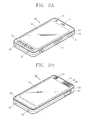
- FIG. 2A is a front perspective view of the mobile terminal according to an embodiment of the present invention
- FIG. 2B is a rear perspective view of the mobile terminal according to an embodiment of the present invention
- the mobile terminal 100 is a bar type mobile terminal.
- the present disclosure is not limited to this, but may be applied to a slide type in which two or more bodies are coupled to each other so as to perform a relative motion, a folder type, or a swing type, a swivel type and the like.
- a body of the mobile terminal 100 has a front surface, side surfaces and a rear surface.
- the body has two ends in a lengthwise direction.
- a case (casing, housing, cover, etc.) forming an outer appearance of the body may include a front case 101 and a rear case 102.
- a space formed by the front case 101 and the rear case 102 may accommodate various components therein.
- At least one intermediate case may further be disposed between the front case 101 and the rear case 102.
- Such cases may be formed by injection-molded synthetic resin, or may be formed using a metallic material such as stainless steel (STS) or titanium (Ti).
- STS stainless steel
- Ti titanium
- At the front case 101 may be disposed a display unit 151, an audio output unit(or an audio output module) 152, a camera 121, user input units 130/131 and 132, a microphone 122, an interface unit 170, etc.
- the display unit 151 occupies most parts of a main surface of the front case 101.
- the audio output unit 152 and the camera 121 are arranged at a region adjacent to one end of the stereoscopic display unit 151, and the user input unit 131 and the microphone 122 are arranged at a region adjacent to another end of the display unit 152.
- the user input unit 131, the interface unit 170, etc. may be arranged on side surfaces of the front case 101 and the rear case 102.
- the microphone 122 is arranged at another end of the body.
- the user input unit 130 is manipulated to receive a command for controlling the operation of the mobile terminal 100, and may include a plurality of manipulation units 131 and 132.
- the manipulation units may be referred to as manipulating portions, and may include any type of ones that can be manipulated in a user's tactile manner.
- Commands inputted through the first or second user input units 131 and 132 may be variously set.
- the first manipulation 131 is configured to input commands such as START, END, SCROLL or the like
- the second manipulation unit 132 is configured to input commands for controlling a level of sound outputted from the audio output unit 152, or commands for converting the current mode of the display unit 151 to a touch recognition mode.
- an audio output unit 152' may be additionally disposed at the rear case 102.
- the audio output unit 152' may implement a stereo function together with the audio output unit 152 (refer to FIG. 2A ), and may be used for calling in a speaker phone mode.
- a power supply unit 190 for supplying power to the mobile terminal 100 is mounted to the body.
- the power supply unit 190 may be mounted in the body, or may be detachably mounted to the body.
- a touch pad 135 for sensing touch may be additionally mounted to the rear case 102.
- the touch pad 135 may be formed to be light-transmissive.
- the display unit 151 is configured to output visual information from two surfaces thereof, the visual information can be recognized through the touch pad 135.
- the information output from the two surfaces can be controlled by the touch pad 135.
- a display may be additionally mounted to the touch pad 135, so that a touch screen can be disposed at the rear case 102.
- a camera 121' may be additionally provided on the rear case 102.
- the camera 121' faces a direction which is opposite to a direction faced by the camera 121 (refer to FIG. 2A ), and may have different pixels from those of the camera 121.
- the camera 121 may operate with relatively lower pixels (lower resolution). Thus, the camera 121 may be useful when a user can capture his face and send it to another party during a video call or the like.
- the camera 121' may operate with a relatively higher pixels (higher resolution) such that it can be useful for a user to obtain higher quality pictures for later use.
- the cameras 121 and 121' may be installed at the body so as to rotate or pop-up.
- a flash 123 and a mirror 124 may be additionally disposed close to the camera 121'.
- the flash 123 operates in conjunction with the camera 121' when taking a picture using the camera 121'.
- the mirror 124 can cooperate with the camera 121' to allow a user to photograph himself in a self-portrait mode.
- An audio output unit 252' may be additionally arranged on a rear surface of the body.
- the audio output unit 252' (refer to FIG. 2A ) may cooperate with the audio output unit 252 (refer to FIG. 2A ) so as to implement a stereo function.
- the audio output unit may be configured to operate as a speakerphone.
- a power supply unit 190 for supplying power to the mobile terminal 100 is mounted to the body.
- the power supply unit 190 may be mounted in the body, or may be detachably mounted to the body.
- the touch pad 135 operates in association with the display unit 151 of the front case 101.
- the touch pad 135 may be disposed on the rear surface of the display unit 151 in parallel.
- the touch pad 135 may have a size equal to or smaller than that of the display unit 151.
- the controller 180 of the mobile terminal may perform a locked state for limiting the input of a command control for an application.
- a locked screen may be output in the locked state, and screen information output on the display unit before the performance of the locked state may be set as the locked screen, based on a user's selection. That is, the screen information output on the display unit before the performance of the locked state may be output as the locked screen in the locked state on the display unit.
- An image objective for changing the locked state into a released state may be output on the locked screen.
- the image objective may be output together with the screen information set as the locked screen on the display unit 151.
- the controller 180 releases the locked state in response to a touch gesture for the image objective, and changes the state of the mobile terminal from the locked state into the released state.
- the locked state is a state in which the user's input of control commands to applications included in the mobile terminal is limited.
- the locked state is used to prevent functions and applications of a mobile terminal having a touch screen (or display unit 151 configured with a touch screen) from being activated or non-activated by the user's unintentional input of a control command in the mobile terminal.
- the user's input a control command input through the touch screen (or display unit 151) or the user input unit 130 can be limited within a set range.
- the released state is a state in which the user's input of control commands to the mobile terminal is not limited.
- the functions and applications of the mobile terminal are activated or non-activated depending on a control command input by a user through the touch screen (or display unit 151) or the user input unit 130.
- the locked state may be performed when the user's input is not sensed by the touch screen (or display unit 151) or the user input unit 130 provided in the mobile terminal for a predetermined time.
- the predetermined time may be changed depending on the user's setting.
- the locked state may be performed when the user presses a special key (e.g., a hold key) provided to the mobile terminal.
- a special key e.g., a hold key
- the special key is previously set to perform the locked state.
- the case where the user's input to the mobile terminal is not sensed for the predetermined time or the case where the user's input for the special key is sensed to perform the locked state can be expressed as 'the locked state is performed when the set condition is satisfied.
- the released state may be performed by the special key again pressed by the user in the locked state or the touch gesture input to the image objective displayed in the locked state.
- the lock screen image (or screen information) displayed on a locked screen in the conventional mobile terminal may be generally a specific image set by a user or controller.
- the specific image may be a static or dynamic image. Therefore, in a case where a locked state is performed, the same specific image is always output on the locked screen.
- the locked state is performed while the user executes a specific function through the mobile terminal, the user desires to continuously receive screen information corresponding to the specific function.
- the execution screen or specific image of the application can be set as a locked screen, based on a user's selection.
- the set execution screen or specific image can be output on the display unit.
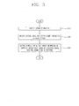
- FIG. 3 is a flowchart illustrating a control method for setting a locked screen in the mobile terminal according to an exemplary embodiment.
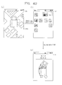
- FIGS. 4A to 4D are conceptual views illustrating the control method of FIG. 3 in the mobile terminal according to an exemplary embodiment.
- screen information is displayed on the display unit 151 (S310).
- the screen information may be any one of an execution screen of any one of a plurality of applications, a screen of home screen page and a menu screen.
- the screen information is output on the display unit 151 in a state in which the mobile terminal is activated, i.e., in a state in which the locked state is not performed.
- the controller 180 may receive a control signal for setting the screen information as a locked screen while the screen information is output on the display unit 151 (S320).
- the control signal may be received through various channels.
- the control signal may be received when a user selects an image objective corresponding to the function of setting the locked screen.
- an execution screen 200 of a specific application e.g., the execution screen 200 of a map-based application is output on the display unit 151 as shown in FIG. 4A (a)
- the control signal may be received, based on an item 210 "Set as locked screen" for setting the execution screen 200 as the locked screen is selected as shown in FIG. 4A (b) .
- the item "Set as locked screen,” as shown in FIG. 4A (b) may be any one of a plurality of functional items for controlling the execution screen 200.
- the control signal related to the item "Set as locked screen” may be received through a separate icon output on the execution screen 200.
- the controller 180 controls the display unit 151 so that the execution screen 200 (or screen information) is output on the display unit 151, based on the received control signal (S330).
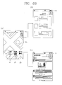
- the controller 180 in the locked state, the controller 180, as shown in FIG. 4A (c) , outputs an execution screen (or screen information) 300 set through the process of setting the locked screen, described in FIGS. 4A (a) and (b) , on the display unit 151.
- screen information (or execution screen) arbitrarily set by the user may be output as the locked screen on the display unit 151, rather than a lock screen image (or moving image) previously set to be output in the locked state.
- the controller 180 may temporarily output the screen information in the locked state and then control the display unit 151 so that the previously set lock screen image is output on the display unit 151.
- the controller 180 may change setting information related to the locked screen so that the screen information (or execution screen) is no longer displayed on the locked screen. Therefore, if the locked state is again performed, the controller 180, as shown in FIG. 4B (c) , may control the display unit 151 so that the previously set lock screen image is output as the locked screen, rather than the screen information (or execution screen) selected by the user.
- the setting information related to the locked screen may be set when the control signal for setting the execution screen of the application as the locked screen is received.
- the controller 180 may receive a screen to be output in the locked state, selected by the user, using another method in addition to the method described above.
- a plurality of graphic objectives 410 and 420 respectively matched to different screen information may be output on a locked screen 300. If a touch input for any one of the plurality of graphic objectives 410 and 420 satisfies a release condition for converting the locked state into a released state, the controller 180 converts the locked state into the released state, and outputs screen information corresponding to the graphic objective on the display unit 151. In a case where the screen information corresponding to the graphic objective is an execution screen of an application, the controller 180 may execute the application.
- the controller 180 In a case where the touch input for the second graphic objective 420 corresponds to the release condition as shown in FIG. 4C (a) , the controller 180, as shown in FIG. 4C (b) , outputs screen information 200 matched to the second graphic objective 420 on the display unit 151 in the released state.
- the controller 180 may execute an application corresponding to the screen information 200, e.g., an application related to position information.
- the controller 180 In a case where the touch input for the first graphic objective 410 corresponds to the release condition as shown in FIG. 4C (a) , the controller 180, as shown in FIG. 4C (c) , outputs screen information 400 corresponding to the home screen page matched to the first graphic objective 410 on the display unit 151 in the released state.
- the controller 180 converts the locked state into the released state and immediately outputs a screen desired by the user, so that it is possible to an inconvenience that the user should reselect an application to be executed in the released state.
- the controller 180 may output the screen information on the locked screen when the screen information corresponds to a predetermined condition, in addition to the method for immediately outputting the screen information on the locked screen in the locked state performed after the control signal for setting the screen information to be displayed on the locked screen is received.
- the predetermined condition may be set based on a user's selection.
- the predetermined condition may be a condition related to ambient environment or state information of the mobile terminal, such as time, weather, position, place or battery capacity of the mobile terminal.
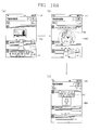
- the controller 180 In a case where the predetermined condition is set to "Near destination" by the user while the execution screen 200 of the map application is set as the locked screen as shown in FIG. 4D (a) , the controller 180, as shown in FIG. 4D (b) , outputs a previously set lock screen image 300a on the locked screen when the mobile terminal 100 is positioned not near the destination. In a case where the mobile terminal is positioned near the destination, the controller 180, as shown in FIG. 4D (c) and (d) , outputs execution screens 300b and 300c of the map application on the locked screen.
- the controller 180 may monitor the position of the mobile terminal at a predetermined interval, and may receive, from the user, detailed information related to how far distant from the destination the execution screen is to be output, etc.
- the controller 180 may output the screen information (or execution screen of the application) set by the user on the locked screen at the time desired by the user.
- the controller 180 may temporarily output the screen information on the display unit 151, rather than the previously set lock screen image.
- the controller 180 may control the display unit 151 so that the screen information is output on the display unit 151 in the locked state.
- the screen information selected by the user can be arbitrarily set as the locked screen, rather than the previously set lock screen image.
- the user can continuously receive the screen information even when the locked state for limiting a control command for an application is performed.
- FIGS. 5A and 5B are conceptual views illustrating a method for receiving a control signal related to the setting of a locked screen in the mobile terminal according to an exemplary embodiment.
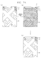
- the controller 180 may set the screen information output on the display unit 151 as a locked screen, based on that a graphic objective for receiving the set locked screen is selected by a user.
- the controller 180 may output the captured image on a locked screen 300.
- the control signal the control signal for capturing the screen information 200 may be received, based on at least a touch input to the display unit 151 or a hot key provided to the mobile terminal.
- the controller 180 may output an execution screen of an application, corresponding to the screen information, on the locked screen 300, based on the control signal. That is, the controller 180 may receive the execution screen of the application provided on the locked screen.
- the user can identify the event in the locked state, even though the locked state is not converted into the released state.
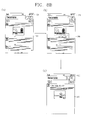
- the controller 180 may perform a locked state. After the reference time elapses, the controller 180, as shown in FIG. 5B (c) , may set the screen information output on the display unit 151 just before the locked state is performed as a locked screen, based on performance of the locked state.
- the controller 180 may perform the locked state and receive a control signal for setting the screen information as the locked screen, based on performance of the locked state.
- the control signal may be received only when the screen information is an execution screen of an application.
- the control signal may be received only when the screen information is an execution screen of a predetermined kind of application.
- the predetermined kind of application may be set according to a user's selection, or may be set according to characteristics of the application.
- the reference time is a time set so that the locked state is performed when a control command is not received for a predetermined time in the mobile terminal.
- the degree of the reference time may be variously set according to the user's setting.
- the screen information output on the display unit before the locked state is performed is set as the locked screen, so that the user can continuously receive necessary information even in the locked state.
- the mobile terminal As described above, in the mobile terminal according to the exemplary embodiment, it is possible to set the screen information output on the display unit as the locked screen, based on the control signal received through various channels.
- FIGS. 6A to 6C are conceptual views illustrating a method for changing a locked screen in the mobile terminal according to an exemplary embodiment.
- the screen information output on the display unit e.g., the execution screen of the application is arbitrarily set as the locked screen, and the existing lock screen image is output as a locked screen in the next locked state when the locked state is released, thereby arbitrarily outputting the screen information on the locked screen.
- the currently output locked screen may be converted into another locked screen in the state in which the locked state is performed.
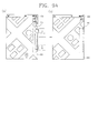
- the controller 180 may output, on the locked screen, a graphic image 310 for outputting a previously set lock screen image on the locked screen, rather than screen information received from a user.
- the controller 180 as shown in FIG. 6A (b) , may output the lock screen image on a locked screen 300b, based on the graphic image 310 being selected by the user.
- a graphic objective for outputting screen information 300a set by the user on the locked screen may be output on the locked screen 300b of FIG. 6A (b) .
- the controller 180 may output thumbnail images (or graphic objectives) 310, 320 and 330 corresponding to the screen information that has been set as the locked screen earlier than a currently output locked screen 300a. If any one of the thumbnail images 310, 320 and 300 is selected by the user, the controller 180, as shown in FIGS. 6B (b) and (c) , may display screen information corresponding to the selected thumbnail image on the display unit 151 in the locked state.
- the controller 180 may change the locked screen, based on a touch input applied on the display unit 151 in the locked state, e.g., a flicking touch input or sliding touch input. That is, the controller 180 may convert a currently output locked screen 300a into other locked screens 300b and 300c.
- the converted locked screen corresponds to the screen information that has been set as the locked screen earlier than the currently output locked screen. That is, the user can receive history information on the screen information that has been set by the user.
- the mobile terminal it is possible to convert the currently output locked screen in the locked state into another locked screen. Further, it is possible to convert the locked screen using various methods other than the method for applying the touch input on the display unit.
- FIGS. 7A and 7B are conceptual views illustrating a method for controlling illumination of the display unit in the mobile terminal according to an exemplary embodiment.
- the controller 180 may allow a locked screen 300 to be identified by a user by maintaining illustration of the display unit 151 for a reference time in the locked state. That is, in a case where the illumination of the display unit 151 is off, the locked state is maintained, but visual information is not displayed on the display unit 151.
- the time for which the illumination of the display unit 151 is maintained as an on-state in the locked state (or the time for which the illumination of the display unit 151 is activated) may be changed by a user's setting.
- the controller 180 may output an image objective 310 on the locked screen, and control the time for which the illumination of the display unit 151 is on, based on that the image objective 310 is selected by the user.
- the controller 180 may allow the illumination of the display unit 151 to be again brightened or to be converted into the on-state, based on selection of the image objective 310 by the user.
- the controller 180 may output a progress bar together with the image objective 310 so that the user can identify the time when the illumination of the display unit 151 is off. If the image objective 310 is selected by the user, the indication of the progress bar may be changed as shown in FIG. 7B (c) .
- a graphic objective capable of controlling the time when the illumination of the display unit is on may be displayed on the display unit using various methods.
- the mobile terminal it is possible to provide a function of controlling the illumination of the display unit on the locked screen 300 so that the user can continuously identify information displayed on the locked screen.
- FIGS. 8A and 8B are conceptual views illustrating a method for updating a locked screen in the mobile terminal according to an exemplary embodiment.
- the controller 180 may control the display unit 151 so that an execution screen of an application is output on the locked screen 300, based on a user's selection.
- the controller 180 may output the execution screen output on the display unit 151 at the time when a control signal for setting the locked screen is received in an image form on the locked screen.
- the controller 180 may control the display unit 151 so that the execution screen of the application itself is output on the locked screen. That is, information on a progressive state of the application or update information related to the application may be displayed on the locked screen.
- the controller 180 may update information corresponding the changed position of the mobile terminal in real time or at a predetermined time interval on the locked screen.
- the controller 180 may output an event occurring in the application, e.g., information on an event "Notification of new script" on the display unit 151. Further, the controller 180 may change the locked screen displayed on the display unit 151 so that the user can receive the information on the event "Notification of new script.”
- the controller 180 can update the execution screen of the application displayed on the locked screen 300 so that the user can receive update information on the application.
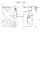
- FIGS. 9A to 9C are conceptual views illustrating a method for receiving a control command in a locked state in the mobile terminal according to an exemplary embodiment.
- a control command for an application is limited by limiting a touch input applied on the display unit 151 in the locked state.
- a control command for controlling an application corresponding to screen information display on the locked screen may be received through a touch input.
- the controller 180 may allow a control command for an application to be received, only on a predetermined region 310 included in the display unit 151.
- an execution screen displayed on the locked screen 300 is scrolled through a touch input on the predetermined region 310, thereby changing the display area of the display unit 151.
- the controller 180 may control the execution screen, i.e., the application by enlarging, reducing or changing the execution screen displayed on the locked screen, based on the touch input on the predetermined region 310.
- the controller 180 may control the display unit 151 so that another region different from the predetermined region 310 is displayed on the locked screen. That is, the controller 180 may control the display unit 151 so that the visual exterior appearance of the predetermined region 310 is different from that of another region.
- the size of the predetermined region 310 may be changed depending on a user's setting. As shown in FIG. 9C (b) , the size of the predetermined region 310 may be changed depending on a touch input applied on the locked screen.
- the controller 180 can control the application even in the locked state.
- the user should change the locked state into the released state so as to apply a control command for an application.
- FIGS. 10A and 10B are conceptual views illustrating a method for changing a locked state into a released state in the mobile terminal according to an exemplary embodiment.
- the method for changing the locked state into the released state while the locked state is being executed may be changed depending on a user's selection.
- the controller 180 may change the locked state into the released state, based on a touch input on the display unit 151.
- the controller 180 as shown in FIG. 10A (b) , may change the method for releasing the locked state, based on a touch input corresponding to a predetermined method on the display unit 151, e.g., a flicking or sliding touch input.
- the controller 180 may release the locked state through a face recognition method rather than the touch input. If the touch input corresponding to the predetermined method on the display unit 151 is again applied, the controller 180, as shown in FIG. 10A (c) , may again change the method for releasing the locked state.
- the controller 180 may change the locked state into the released state through voice recognition.
- the controller 180 may recognize a function to be executed through voice or the name of an application together with the voice recognition, so that it is possible to release the locked state and immediately execute the recognized function or application.
- the controller 180 may simultaneously receive a function to be executed or voice for an application together with a control command for releasing the locked state. For example, the controller 180 may recognize the function to be executed or the name of the application through the voice applied from the user, so that it is possible to release the locked state and simultaneously execute the recognized function or application.
- various methods for releasing the locked state can be provided in the locked state so that the user can release the locked state using a suitable method according to the user's situation. Further, in the mobile terminal according to the exemplary embodiment, the locked state is released, and simultaneously, a user's desired function or application is executed, so that it is possible to save a time for which the user applies a separate control command for performing the desired function after releasing the locked state.
- an execution screen of an application can be set as the locked screen.
- the user can receive information necessary for the user through the execution screen of the application, set as the locked screen, even in the locked state.
- the execution screen of the application is updated, thereby providing up-to-date information to the user.
- the aforementioned methods can be embodied as computer readable codes on a computer-readable recording medium.
- the computer readable recording medium include a ROM, RAM, CD-ROM, magnetic tapes, floppy disks, optical data storage devices, and carrier waves (such as data transmission through the Internet).
Landscapes
- Engineering & Computer Science (AREA)
- General Engineering & Computer Science (AREA)
- Theoretical Computer Science (AREA)
- Computer Security & Cryptography (AREA)
- Human Computer Interaction (AREA)
- Physics & Mathematics (AREA)
- General Physics & Mathematics (AREA)
- Signal Processing (AREA)
- Computer Networks & Wireless Communication (AREA)
- Telephone Function (AREA)
- User Interface Of Digital Computer (AREA)
- Controls And Circuits For Display Device (AREA)
Applications Claiming Priority (1)
| Application Number | Priority Date | Filing Date | Title |
|---|---|---|---|
| KR1020120068739A KR101977074B1 (ko) | 2012-06-26 | 2012-06-26 | 이동 단말기 및 그것의 제어방법 |
Publications (2)
| Publication Number | Publication Date |
|---|---|
| EP2680122A2 true EP2680122A2 (de) | 2014-01-01 |
| EP2680122A3 EP2680122A3 (de) | 2016-04-20 |
Family
ID=48747878
Family Applications (1)
| Application Number | Title | Priority Date | Filing Date |
|---|---|---|---|
| EP13003179.2A Withdrawn EP2680122A3 (de) | 2012-06-26 | 2013-06-21 | Mobiles Endgerät und Steuerungsverfahren dafür |
Country Status (4)
| Country | Link |
|---|---|
| US (1) | US20130342487A1 (de) |
| EP (1) | EP2680122A3 (de) |
| KR (1) | KR101977074B1 (de) |
| CN (1) | CN103513923A (de) |
Families Citing this family (27)
| Publication number | Priority date | Publication date | Assignee | Title |
|---|---|---|---|---|
| US8977255B2 (en) | 2007-04-03 | 2015-03-10 | Apple Inc. | Method and system for operating a multi-function portable electronic device using voice-activation |
| JP5284504B1 (ja) * | 2012-03-02 | 2013-09-11 | 株式会社東芝 | 電子機器、電子機器の制御方法、制御プログラム及び記録媒体 |
| DE112014000709B4 (de) | 2013-02-07 | 2021-12-30 | Apple Inc. | Verfahren und vorrichtung zum betrieb eines sprachtriggers für einen digitalen assistenten |
| US9715875B2 (en) | 2014-05-30 | 2017-07-25 | Apple Inc. | Reducing the need for manual start/end-pointing and trigger phrases |
| US10170123B2 (en) | 2014-05-30 | 2019-01-01 | Apple Inc. | Intelligent assistant for home automation |
| CN104010230B (zh) * | 2014-06-17 | 2015-09-23 | 合一网络技术(北京)有限公司 | 锁屏状态下的视频播放的方法和系统 |
| US9338493B2 (en) | 2014-06-30 | 2016-05-10 | Apple Inc. | Intelligent automated assistant for TV user interactions |
| KR101602866B1 (ko) * | 2014-07-18 | 2016-03-14 | 세기 리미티드 | 차량 원격 제어 시스템 및 그 방법 |
| US9886953B2 (en) | 2015-03-08 | 2018-02-06 | Apple Inc. | Virtual assistant activation |
| US9998547B2 (en) * | 2015-06-25 | 2018-06-12 | Livio, Inc. | Vehicle computing systems and methods for delivery of a mobile device lockout icon |
| US10747498B2 (en) | 2015-09-08 | 2020-08-18 | Apple Inc. | Zero latency digital assistant |
| US10223066B2 (en) * | 2015-12-23 | 2019-03-05 | Apple Inc. | Proactive assistance based on dialog communication between devices |
| US10586535B2 (en) | 2016-06-10 | 2020-03-10 | Apple Inc. | Intelligent digital assistant in a multi-tasking environment |
| DK201670540A1 (en) | 2016-06-11 | 2018-01-08 | Apple Inc | Application integration with a digital assistant |
| US12197817B2 (en) | 2016-06-11 | 2025-01-14 | Apple Inc. | Intelligent device arbitration and control |
| US11204787B2 (en) | 2017-01-09 | 2021-12-21 | Apple Inc. | Application integration with a digital assistant |
| DK201770428A1 (en) | 2017-05-12 | 2019-02-18 | Apple Inc. | LOW-LATENCY INTELLIGENT AUTOMATED ASSISTANT |
| DK179496B1 (en) | 2017-05-12 | 2019-01-15 | Apple Inc. | USER-SPECIFIC Acoustic Models |
| US10303715B2 (en) | 2017-05-16 | 2019-05-28 | Apple Inc. | Intelligent automated assistant for media exploration |
| CN107132908B (zh) * | 2017-06-08 | 2020-02-14 | 青岛海信移动通信技术股份有限公司 | 图像更新方法及装置 |
| US10818288B2 (en) | 2018-03-26 | 2020-10-27 | Apple Inc. | Natural assistant interaction |
| DK180639B1 (en) | 2018-06-01 | 2021-11-04 | Apple Inc | DISABILITY OF ATTENTION-ATTENTIVE VIRTUAL ASSISTANT |
| US11348573B2 (en) | 2019-03-18 | 2022-05-31 | Apple Inc. | Multimodality in digital assistant systems |
| DK201970509A1 (en) | 2019-05-06 | 2021-01-15 | Apple Inc | Spoken notifications |
| US11307752B2 (en) | 2019-05-06 | 2022-04-19 | Apple Inc. | User configurable task triggers |
| US11490204B2 (en) | 2020-07-20 | 2022-11-01 | Apple Inc. | Multi-device audio adjustment coordination |
| US11438683B2 (en) | 2020-07-21 | 2022-09-06 | Apple Inc. | User identification using headphones |
Family Cites Families (18)
| Publication number | Priority date | Publication date | Assignee | Title |
|---|---|---|---|---|
| FI115190B (fi) * | 2003-01-21 | 2005-03-15 | Nokia Corp | Menetelmä paikkariippuvan toiminnon käynnistämiseksi, järjestelmä ja laite |
| US9197738B2 (en) * | 2008-12-04 | 2015-11-24 | Microsoft Technology Licensing, Llc | Providing selected data through a locked display |
| US8539382B2 (en) * | 2009-04-03 | 2013-09-17 | Palm, Inc. | Preventing unintentional activation and/or input in an electronic device |
| KR101537706B1 (ko) * | 2009-04-16 | 2015-07-20 | 엘지전자 주식회사 | 이동 단말기 및 그 제어 방법 |
| US9563350B2 (en) * | 2009-08-11 | 2017-02-07 | Lg Electronics Inc. | Mobile terminal and method for controlling the same |
| US8434153B2 (en) * | 2009-08-24 | 2013-04-30 | Microsoft Corporation | Application display on a locked device |
| US20110163972A1 (en) * | 2010-01-06 | 2011-07-07 | Freddy Allen Anzures | Device, Method, and Graphical User Interface for Interacting with a Digital Photo Frame |
| EP2383636A1 (de) * | 2010-04-29 | 2011-11-02 | Acer Incorporated | Bildschirmfreigabeverfahren und elektronische Vorrichtung dafür |
| KR20120007686A (ko) * | 2010-07-15 | 2012-01-25 | 삼성전자주식회사 | 터치 디바이스에서 기능 제어 방법 및 장치 |
| KR101669967B1 (ko) * | 2010-08-23 | 2016-10-27 | 엘지전자 주식회사 | 이동단말기 및 그 제어방법 |
| KR101685991B1 (ko) * | 2010-09-30 | 2016-12-13 | 엘지전자 주식회사 | 이동 단말기 및 이동 단말기의 제어 방법 |
| WO2012060486A1 (en) * | 2010-11-02 | 2012-05-10 | Lg Electronics Inc. | Mobile terminal and method of controlling the same |
| KR101808625B1 (ko) * | 2010-11-23 | 2018-01-18 | 엘지전자 주식회사 | 콘텐츠 제어 장치 및 그 방법 |
| KR101788048B1 (ko) * | 2010-12-02 | 2017-10-19 | 엘지전자 주식회사 | 이동 단말기 및 그 제어방법 |
| CN102707870B (zh) * | 2011-02-17 | 2015-07-01 | 宏达国际电子股份有限公司 | 提供屏幕锁定的背景的方法及电子装置 |
| US8638385B2 (en) * | 2011-06-05 | 2014-01-28 | Apple Inc. | Device, method, and graphical user interface for accessing an application in a locked device |
| CN102236527B (zh) * | 2011-07-15 | 2014-06-25 | Tcl集团股份有限公司 | 一种触摸屏解锁的方法、装置及触摸屏终端 |
| CN102231097A (zh) * | 2011-07-28 | 2011-11-02 | 青岛海信移动通信技术股份有限公司 | 一种屏幕解锁方法及装置 |
-
2012
- 2012-06-26 KR KR1020120068739A patent/KR101977074B1/ko not_active Expired - Fee Related
-
2013
- 2013-06-21 EP EP13003179.2A patent/EP2680122A3/de not_active Withdrawn
- 2013-06-24 US US13/925,582 patent/US20130342487A1/en not_active Abandoned
- 2013-06-26 CN CN201310259537.5A patent/CN103513923A/zh active Pending
Non-Patent Citations (1)
| Title |
|---|
| None |
Also Published As
| Publication number | Publication date |
|---|---|
| EP2680122A3 (de) | 2016-04-20 |
| US20130342487A1 (en) | 2013-12-26 |
| KR101977074B1 (ko) | 2019-05-10 |
| CN103513923A (zh) | 2014-01-15 |
| KR20140000930A (ko) | 2014-01-06 |
Similar Documents
| Publication | Publication Date | Title |
|---|---|---|
| EP2680122A2 (de) | Mobiles Endgerät und Steuerungsverfahren dafür | |
| US9794394B2 (en) | Mobile terminal | |
| US9367206B2 (en) | Displaying indicators that indicate ability to change a size of a widget on a display of a mobile terminal | |
| US9996249B2 (en) | Mobile terminal and method of controlling the mobile terminal | |
| US10241743B2 (en) | Mobile terminal for matching displayed text with recorded external audio and method of controlling the mobile terminal | |
| US8914064B2 (en) | Mobile terminal and method of controlling the mobile terminal | |
| US9965166B2 (en) | Mobile terminal and method of controlling the same | |
| US9125017B2 (en) | Mobile terminal and schedule notifying method thereof | |
| US9293112B2 (en) | Mobile terminal and control method thereof | |
| EP2428947A2 (de) | Endgerät und Verfahren zum gemeinsamen Nutzen von Inhalten für ein Endgerät | |
| EP2693307A1 (de) | Mobiles Kommunikationsgerät interagierend mit einem externen elektronischen Schreiber mit Farbsensor | |
| US9746948B2 (en) | Mobile terminal and control method thereof | |
| US9448720B2 (en) | Mobile terminal and control method thereof | |
| US9753632B2 (en) | Mobile terminal and control method thereof | |
| US10516829B2 (en) | Mobile terminal and method for controlling same | |
| KR101172663B1 (ko) | 이동 단말기 및 그 애플리케이션 그룹화 방법 | |
| EP2824557B1 (de) | Mobiles Endgerät und Verfahren zur Steuerung des mobilen Endgerätes | |
| EP2680134A1 (de) | Mobiles Endgerät und Steuerungsverfahren dafür | |
| KR101966320B1 (ko) | 이동 단말기 및 그것의 제어방법 | |
| KR20110062090A (ko) | 이동단말기 및 그의 데이터 전송 방법 | |
| KR20110139791A (ko) | 이동 통신 단말기에서 증강현실을 이용한 메신저 제공방법 | |
| KR20150020785A (ko) | 이동 단말기 및 그것의 제어방법 | |
| KR20100038930A (ko) | 이동 단말기 및 그 제어 방법 | |
| KR20140054937A (ko) | 이동단말 제어방법 |
Legal Events
| Date | Code | Title | Description |
|---|---|---|---|
| PUAI | Public reference made under article 153(3) epc to a published international application that has entered the european phase |
Free format text: ORIGINAL CODE: 0009012 |
|
| 17P | Request for examination filed |
Effective date: 20130621 |
|
| AK | Designated contracting states |
Kind code of ref document: A2 Designated state(s): AL AT BE BG CH CY CZ DE DK EE ES FI FR GB GR HR HU IE IS IT LI LT LU LV MC MK MT NL NO PL PT RO RS SE SI SK SM TR |
|
| AX | Request for extension of the european patent |
Extension state: BA ME |
|
| PUAL | Search report despatched |
Free format text: ORIGINAL CODE: 0009013 |
|
| AK | Designated contracting states |
Kind code of ref document: A3 Designated state(s): AL AT BE BG CH CY CZ DE DK EE ES FI FR GB GR HR HU IE IS IT LI LT LU LV MC MK MT NL NO PL PT RO RS SE SI SK SM TR |
|
| AX | Request for extension of the european patent |
Extension state: BA ME |
|
| RIC1 | Information provided on ipc code assigned before grant |
Ipc: G06F 3/0488 20130101AFI20160315BHEP Ipc: G06F 3/041 20060101ALI20160315BHEP Ipc: H04M 1/67 20060101ALI20160315BHEP |
|
| STAA | Information on the status of an ep patent application or granted ep patent |
Free format text: STATUS: EXAMINATION IS IN PROGRESS |
|
| 17Q | First examination report despatched |
Effective date: 20180305 |
|
| STAA | Information on the status of an ep patent application or granted ep patent |
Free format text: STATUS: THE APPLICATION HAS BEEN WITHDRAWN |
|
| 18W | Application withdrawn |
Effective date: 20180627 |