EP2680127B1 - Bilderzeugungssystem und Verfahren, mit dem Client-Geräte via Druckserver über in einer Bilderzeugungsvorrichtung aufgetretene Ereignisse benachrichtigt werden - Google Patents
Bilderzeugungssystem und Verfahren, mit dem Client-Geräte via Druckserver über in einer Bilderzeugungsvorrichtung aufgetretene Ereignisse benachrichtigt werden Download PDFInfo
- Publication number
- EP2680127B1 EP2680127B1 EP13174126.6A EP13174126A EP2680127B1 EP 2680127 B1 EP2680127 B1 EP 2680127B1 EP 13174126 A EP13174126 A EP 13174126A EP 2680127 B1 EP2680127 B1 EP 2680127B1
- Authority
- EP
- European Patent Office
- Prior art keywords
- job
- image forming
- client
- address
- Prior art date
- Legal status (The legal status is an assumption and is not a legal conclusion. Google has not performed a legal analysis and makes no representation as to the accuracy of the status listed.)
- Active
Links
Images



Classifications
-
- G—PHYSICS
- G06—COMPUTING OR CALCULATING; COUNTING
- G06F—ELECTRIC DIGITAL DATA PROCESSING
- G06F3/00—Input arrangements for transferring data to be processed into a form capable of being handled by the computer; Output arrangements for transferring data from processing unit to output unit, e.g. interface arrangements
- G06F3/12—Digital output to print unit, e.g. line printer, chain printer
- G06F3/1201—Dedicated interfaces to print systems
- G06F3/1202—Dedicated interfaces to print systems specifically adapted to achieve a particular effect
- G06F3/1203—Improving or facilitating administration, e.g. print management
- G06F3/1207—Improving or facilitating administration, e.g. print management resulting in the user being informed about print result after a job submission
-
- G—PHYSICS
- G06—COMPUTING OR CALCULATING; COUNTING
- G06F—ELECTRIC DIGITAL DATA PROCESSING
- G06F3/00—Input arrangements for transferring data to be processed into a form capable of being handled by the computer; Output arrangements for transferring data from processing unit to output unit, e.g. interface arrangements
- G06F3/12—Digital output to print unit, e.g. line printer, chain printer
- G06F3/1201—Dedicated interfaces to print systems
- G06F3/1223—Dedicated interfaces to print systems specifically adapted to use a particular technique
- G06F3/1237—Print job management
- G06F3/1259—Print job monitoring, e.g. job status
-
- G—PHYSICS
- G06—COMPUTING OR CALCULATING; COUNTING
- G06F—ELECTRIC DIGITAL DATA PROCESSING
- G06F3/00—Input arrangements for transferring data to be processed into a form capable of being handled by the computer; Output arrangements for transferring data from processing unit to output unit, e.g. interface arrangements
- G06F3/12—Digital output to print unit, e.g. line printer, chain printer
- G06F3/1201—Dedicated interfaces to print systems
- G06F3/1278—Dedicated interfaces to print systems specifically adapted to adopt a particular infrastructure
- G06F3/1285—Remote printer device, e.g. being remote from client or server
- G06F3/1288—Remote printer device, e.g. being remote from client or server in client-server-printer device configuration
Definitions
- the present disclosure relates to an image forming system and an image forming method in which a client apparatus is notified via a print server of an event generated in an image forming apparatus.
- the print server Since the print server notifies each client of status changes of the statuses of jobs, the amount of communication traffic on the network is increased. Usually, it suffices for each user to know of a status change in his/her job.
- the present invention provides a system as defined in claim 1.
- the system may include the features of any one or more of dependent claims 2 to 8.
- the present invention also provides a method as defined in claim 9.
- the method may include the features of any one or more of dependent claims 10 to 16.
- the present disclosure relates to an image forming system and an image forming method that cause the amount of traffic on a network to be reduced by omitting unnecessary event notifications transmitted from a print server to each client apparatus.
- An image forming system includes a client apparatus, a print server and an image forming apparatus, each of which are coupled to a network.
- the client apparatus includes a status monitor, a printer driver, and a client-side notification service.
- the printer driver is configured to i) convert document data into print job data, ii) generate a job ID of the print job data, iii) provide the job ID to a client-side notification service of the client apparatus, and iv) transmit the print job data to the image forming apparatus via the print server.
- the client-side notification service is configured to i) transmit the provided job ID together with an IP address of the client apparatus to a server-side notification service of the print server via the network and ii) cause content of an event received from the server-side notification service to be displayed on a status monitor.
- the print server includes a job address table and a server-side notification service.
- the job address table includes a field in which the IP address of the client apparatus is associated with the job ID.
- the server-side notification service is configured to i) register the job ID and the IP address received from the client-side notification service in the job address table, ii) receive content of an event transmitted from the image forming apparatus via the network, iii) read an IP address associated with a job ID included in the content of the event from the job address table when the event is a change in job status, and iv) transmit the content of the event to the client-side notification service of the client apparatus having the read IP address.
- An image forming method is performed by a client apparatus that is coupled to a network, a print server that is coupled to the network, and an image forming apparatus that is coupled to the network.
- the client apparatus converts document data into print job data, generates a job ID of the print job data, transmits the print job data to the image forming apparatus via the print server, transmits the job ID together with an IP address of the client apparatus to the print server, and causes content of an event received from the print server to be displayed on a status monitor of the client apparatus.
- the print server registers the job ID and the IP address received from the client apparatus in the job address table, receives content of an event transmitted from the image forming apparatus, reads the IP address associated with the job ID included in the content of the event from the job address table when the event is a change in job status, and transmits the content of the event to the client apparatus having the read IP address.
- Fig. 1 is a schematic diagram illustrating the configuration of an image forming system according to a first embodiment of the present disclosure.
- a print server 10 used as a manager computer and a print server (i) N client apparatus PCs 10-1 to 10-N, and (iii) an image forming apparatus 20 are coupled to one another via a network 30.
- the network is configured to cause the print server 10 to communicate with the image forming apparatus 20 and to cause the print server 10 to communicate with the client apparatus PCs 10-1 to 10-N.
- Fig. 2 is a block diagram illustrating the hardware configurations of the print server 10 and the image forming apparatus 20 that form part of the image forming system.
- a central processing unit (CPU) 11 is coupled to a programmable read only memory (PROM) 13, a dynamic random access memory (DRAM) 14, a network interface 15, an auxiliary storage unit 16, an input unit 17, and a display unit 18 via an interface 12.
- PROM programmable read only memory
- DRAM dynamic random access memory
- network interface 15 an auxiliary storage unit 16
- input unit 17 an input unit 17
- display unit 18 a display unit 18
- Multiple types of interfaces are represented as a single functional block 12.
- the hardware configurations of the client apparatus PCs 10-1 to 10-N are similar to the hardware configuration of the PC 10.
- the PROM 13 which is, for example, a flash memory, stores a basic input/output system (BIOS).
- BIOS basic input/output system
- the DRAM 14 is used as the main memory.
- the auxiliary storage unit 16 stores an operating system (OS), various drivers, and applications that realize the functions of the manager computer and the print server.
- the input unit may include, for example, a keyboard and a pointing device.
- a CPU 21 is coupled via an interface 22 to a PROM 23, a DRAM 24, a network interface 25, an auxiliary storage unit 26, an operation panel 27, a scanner 28, a printer 29, and a fax modem 200.
- the PROM 23 which may be, for example, a flash memory, may store a BIOS, an OS, various drivers, and various applications that realize the various functions of the image forming apparatus.
- the DRAM 24 is used as the main memory.
- the auxiliary storage unit 26 stores print data, image data read by the scanner 28, document data received from the client apparatus PCs 10-1 to 10-N via the print server 10, and facsimile reception data as document files.
- the operation panel 27 includes an input unit and a display unit.
- the scanner 28 changes an image on a paper medium to an electronic image, and an electronic image file is used for printing, facsimile transmission, or file transmission.
- the printer 29 includes a print engine, a paper feed unit, a paper transport unit, and a paper output unit. Based on provided bitmap data generated in the DRAM 24, an electrostatic latent image is formed on a photoconductor drum. The electrostatic latent image is developed with toner, a toner image is transferred to paper and fixed thereon, and the paper is output.
- the network interfaces 15 and 25 are coupled to the network 30.
- Fig. 3 is a block diagram illustrating the functional configurations of the print server 10, the client PC 10-1, and the image forming apparatus 20, each of which are part of the image forming system.
- the client PC 10-1 in this figure is also representative of the client PCs 10-2 to 10-N.
- the configurations of the PCs 10-2 to 10-N are similar to the configuration of the PC 10-1.
- the OS is assumed to be Windows®.
- Fig. 4A is a flowchart illustrating the operations of functional blocks 40 to 42 in the client PC 10-1.
- an application 40 converts document data to print job data by calling a function within a Graphic Device Interface (GDI) library 41.
- a GDI function (i) converts GDI drawing data to page description language (PDL) data that can be interpreted by the image forming apparatus 20 and (ii) writes the data into a first spool file 43, both via a printer driver 42.
- PDL page description language
- step S1 the conversion process for a single job ends when the application 40 calls the EndDoc function within the GDI library 41.
- the printer driver 42 generates a globally unique identifier (GUID), and writes the GUID into the first spool file 43 as a job ID.
- GUID globally unique identifier
- the printer driver 42 by providing the job ID to a client-side notification service 44, requests registration of the job ID.
- the client-side notification service 44 which is a resident program, is activated by the OS at power-on of the client PC 10-1 and operates in the background so as to always receive input.
- Fig. 4B is a flowchart illustrating the process of the client-side notification service 44.
- step S10 when the client-side notification service 44 receives a request for registration of a job ID, the flow proceeds to step S11; otherwise the flow proceeds to step S12 described later.
- step S11 the client-side notification service 44 transmits, together with the IP address of the client PC 10-1, the job ID to be registered to a server-side notification service 51 via a first network communication unit 46, the network 30, and a second network communication unit 50.
- the server-side notification service 51 which is a resident program similar to the client-side notification service 44, is activated by the OS at power-on of the client PC 10-1 and operates in the background so as to always receive input.
- the server-side notification service 51 upon receipt of the job ID and the IP address, registers these as a single record in a job address table 52 illustrated in Fig. 5A .
- Communication between the client-side notification service 44 and the server-side notification service 51 is performed using a Simple Object Access Protocol (SOAP) or a Simple Network Management Protocol (SNMP).
- SOAP Simple Object Access Protocol
- SNMP Simple Network Management Protocol
- a first spooler 45 puts the identifier of the print job data in a queue. Every time an identifier is taken out from the head of the queue, the first spooler 45 supplies the first spool file 43 to a second spooler 53 via the first network communication unit 46 and the second network communication unit 50.
- the second spooler 53 causes a port monitor 56 to transmit (via a language monitor 55) second spool files 54 to the image forming apparatus 20 in the order in which they were spooled.
- the port monitor 56 transmits the second spool file 54 to a main control unit 61 via both the second network communication unit 50 and a third network communication unit 60.
- Work area 62 includes a buffer area in which the main control unit 61 stores print job data that is included in the received second spool file 54. After storing print job data included in the received second spool file 54, the main control unit 61 develops the print job data into bitmap data using an image processing unit 63. The main control unit 61 prints an image based on the bitmap data by (i) supplying the developed bitmap data to a print engine 65 via an engine controller 64 and (ii) controlling a paper feed/output mechanism 67 via a paper feed/output mechanism controller 66.
- the main control unit 61 transmits the content of the error as a status change event of the image forming apparatus 20 to the server-side notification service 51 via the third network communication unit 60 and the second network communication unit 50.
- the content of an event includes a status code and, if the status code indicates a job status, a job ID.
- Fig. 5B is a schematic diagram illustrating the configuration of an event table 47 showing the relationship between a status code and the name of the status code.
- the two highest-order digits of the status code represent a status type code.
- the two highest-order digits of the status code indicating "01" show that the type of status is a job.
- the two highest-order digits of the status code indicating "02” show that the type of status is an image forming apparatus.
- "Start”, “Stop”, “Pause”, “Resume” and “Completed” which are the names of the status codes, respectively indicate the starting, stopping, pausing, resumption, and completion of a job.
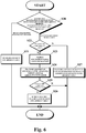
- Fig. 6 is a flowchart illustrating the process of the server-side notification service 51.
- step S20 the flow proceeds to step S21 when the server-side notification service 51 receives a request for registration of a job ID from the client-side notification service 44.
- step S20 the flow proceeds to step S22 when the server-side notification service 51 receives a request for notification from the main control unit 61.
- step S22 when the status type code indicates a job ("01"), the flow proceeds to step S23. Otherwise, for example, when the status type code indicates an image forming apparatus ("02"), the flow proceeds to step S27.
- step S23 the server-side notification service 51 searches the job address table 52 using the job ID as the key.
- step S24 when a record is found in the search, the server-side notification service 51 transmits the content of the event, along with an IP address included in the record as the transmission address, to the client-side notification service 44 via the second network communication unit 50 and the first network communication unit 46.
- step S12 illustrated in Fig. 4B the client-side notification service 44, after converting the status code included in the content of the event to the corresponding name by referring to the event table 47, provides a status monitor 48 with the name of the event together with the job ID and any other content, such as a toner level, included in the content of the event.
- a status display window (not illustrated) is updated. Note that when the status display window is not being displayed, the status display window is displayed as a popup window.
- step S25 when the status code indicates the completion of the job, the flow proceeds to step S26; otherwise, the process illustrated in Fig. 6 ends.
- step S26 the server-side notification service 51 (i) removes from the job address table 52 the record corresponding to the job ID and (ii) finishes the process illustrated in Fig. 6 .
- step S27 the server-side notification service 51 transmits the content of the event to the client-side notification services 44 with all the IP addresses registered in the job address table 52 as the destination addresses.
- a user can display only the job status of his/her own job on the status monitor 48. Further, the amount of communication traffic on the network 30 can be reduced.
- Fig. 7 is a block diagram illustrating the functional configurations of a print server 10A, a client apparatus 10-1A, and an image forming apparatus 20A, each of which are part of the image forming system according to a second embodiment of the present disclosure.
- a language monitor 55A upon receipt of a second spool file 54A from a second spooler 53A, provides both a job ID and an IP address included in this file to a server-side notification service 51A and requests registration.
- the server-side notification service 51A registers, in the job address table 52 illustrated in Fig. 5A , a record including both the job ID and IP address.
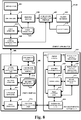
- Fig. 8 is a block diagram illustrating the functional configurations of a print server 10B, a client apparatus 10-1B, and an image forming apparatus 20B, each of which are part of the image forming system, according to a third embodiment of the present disclosure.
- the print server 10B includes a first USB communication unit 57B, and the image forming apparatus 20B includes a second USB communication unit 60B.
- the print server 10 and the image forming apparatus 20B are locally coupled to each other.
- configurations and operations of other configuration blocks in the third embodiment are the same as those in the first embodiment or the second embodiment.
- the configuration of the image forming apparatus in the third embodiment is applicable to the image forming systems of the above-described first and second embodiments.
- a configuration may be employed in which the application 40 writes data into the spool file 43 in an Extended Meta File (EMF) format using the GDI library 41, and a printer driver provided in the spooler 53 converts EMF data into PDL data.
- EMF Extended Meta File
- a configuration may be employed in which the language monitor 55 is omitted.
Landscapes
- Engineering & Computer Science (AREA)
- Theoretical Computer Science (AREA)
- Human Computer Interaction (AREA)
- Physics & Mathematics (AREA)
- General Engineering & Computer Science (AREA)
- General Physics & Mathematics (AREA)
- Accessory Devices And Overall Control Thereof (AREA)
- Facsimiles In General (AREA)
Claims (16)
- Bilderzeugungssystem mit:einem Clientgerät (10-1), das mit einem Netzwerk (30) gekoppelt ist;einem Druckserver (10), der mit dem Netzwerk (30) gekoppelt ist; undeinem Bilderzeugungsgerät (20), das mit dem Netzwerk (30) gekoppelt ist,wobei das Clientgerät (10-1) Folgendes aufweist:einen Statusmonitor (48), der einen Inhalt eines Ereignisses in dem Bilderzeugungsgerät (20) anzeigt;einen clientseitigen Mitteilungsdienst (44); undeinen Druckertreiber (42), undwobei der Druckserver (10) Folgendes aufweist:einen serverseitigen Mitteilungsdienst (51); undeine Jobadressentabelle (52) einschließlich eines Feldes, in dem die IP-Adresse des Clientgerätes (10-1) mit einer Job-ID als eine einzige Aufzeichnung verknüpft ist,wobei der Druckertreiber (42) dazu konfiguriert ist,i) Dokumentendaten zu Druckjobdaten zu wandeln (S0),ii) eine Job-ID der Druckjobdaten zu erzeugen,iii) die Job-ID für den clientseitigen Mitteilungsdienst (44) des Clientgeräts (10-1) bereitzustellen (S1), undiv) die Druckjobdaten zu dem Bilderzeugungsgerät (20) über den Druckserver (10) zu übertragen; undwobei der clientseitige Mitteilungsdienst (44) dazu konfiguriert ist,i) die bereitgestellte Job-ID zusammen mit einer IP-Adresse des Clientgerätes (10-1) zu dem serverseitigen Mitteilungsdienst (51) des Druckservers (10) über das Netzwerk (30) zu übertragen (S11) undii) den Inhalt eines Ereignisses, der von dem serverseitigen Mitteilungsdienst (51) aufgenommen ist, zum Anzeigen an dem Statusmonitor (48) zu veranlassen (S12),wobei der serverseitige Mitteilungsdienst (51) dazu konfiguriert ist,i) die Job-ID und die IP-Adresse, die von dem clientseitigen Mitteilungsdienst (44) aufgenommen wurden, in der Jobadressentabelle (52) zu registrieren (S21),ii) den Inhalt eines Ereignisses einschließlich eines Statuscodes aufzunehmen, der von dem Bilderzeugungsgerät (20) über das Netzwerk (30) übertragen ist, wobei der Inhalt des Ereignisses des Weiteren die Job-ID enthält, falls der Statuscode einen Jobstatus angibt, der entweder "Start", "Stopp", "Pause", "Wiederaufnehmen" oder "Beendet" enthält,iii) die IP-Adresse, die mit der in dem Inhalt des Ereignisses enthaltenen Job-ID verknüpft ist, aus der Jobadressentabelle (52) zu lesen und den Inhalt des Ereignisses zu dem clientseitigen Mitteilungsdienst (44) des Clientgerätes (10-1) zu übertragen (S24), das die gelesene IP-Adresse hat, falls der Statuscode den Jobstatus angibt, undden Inhalt des Ereignisses zu den clientseitigen Mitteilungsdiensten (44) von allen Clients mit IP-Adressen zu übertragen, die in der Jobadressentabelle (52) registriert sind, falls der Statuscode nicht einen Jobstatus sondern einen Bilderzeugungsgerätestatus angibt, der entweder "Bereit", "Drucken" oder "Toner aus" enthält, und
wobei die Erzeugung der Job-ID ein Erzeugen eines global eindeutigen Identifikators (GUID) und ein Schreiben des GUID in eine Pufferdatei (43) als die Job-ID aufweist. - Bilderzeugungssystem gemäß Anspruch 1,
wobei, wenn das Ereignis eine Beendigung des Druckjobs ist, der serverseitige Mitteilungsdienst (51) des Weiteren dazu konfiguriert ist, aus der Jobadressentabelle (52) eine Aufzeichnung zu löschen (S26), die die Job-ID des Druckjobs und die mit der Job-ID verknüpfte IP-Adresse enthält. - Bilderzeugungssystem gemäß Anspruch 1,wobei das Clientgerät (10-1) des Weiteren einen ersten Puffer (45) aufweist und der Druckserver (10) des Weiteren einen zweiten Puffer (53) aufweist,wobei der erste Puffer (45), wenn ein Schreiben der Druckjobdaten in die Pufferdatei (43) beendet ist, dazu konfiguriert ist, einen Identifikator der Druckjobdaten in eine Warteschlange zu setzen und die Pufferdatei (43) zu dem zweiten Puffer (53) jedes Mal dann zuzuführen, wenn der Identifikator aus einem Kopf der Warteschlange akquiriert wird.
- Bilderzeugungssystem gemäß Anspruch 3,wobei der Druckserver (10) des Weiteren einen Sprachmonitor (55) und einen Portmonitor (56) aufweist, undwobei der zweite Puffer (53) dazu konfiguriert ist, ein Übertragen der Pufferdatei (43) zu dem Portmonitor (56) über den Sprachmonitor (55) in der Pufferreihenfolge zu veranlassen.
- Bilderzeugungssystem gemäß Anspruch 4,wobei der Druckertreiber (42) des Weiteren dazu konfiguriert ist, die IP-Adresse des Clientgerätes (10-1) in die Pufferdatei (43) zu schreiben, undwobei der Sprachmonitor (55) dazu konfiguriert ist, die Job-ID und die IP-Adresse aus den Druckjobdaten zu akquirieren und die Job-ID und die IP-Adresse für den serverseitigen Mitteilungsdienst (51) bereitzustellen.
- Bilderzeugungssystem gemäß Anspruch 1,
wobei das Bilderzeugungsgerät (20) lokal an den Druckserver (10) gekoppelt ist und das Clientgerät (10-1) und der Druckserver (10) über das Netzwerk (30) miteinander gekoppelt sind. - Bilderzeugungssystem gemäß Anspruch 1,
wobei eine Kommunikation zwischen dem clientseitigen Mitteilungsdienst (44) und dem serverseitigen Mitteilungsdienst (51) unter Verwendung eines Simple-Objekt-Access-Protokolls (SOAP) bewirkt wird. - Bilderzeugungssystem gemäß Anspruch 1,
wobei ein Wandeln der Dokumentendaten zu den Druckjobdaten ein Aufrufen einer Funktion innerhalb einer Graphic-Device-Interface-(GDI)-Bibliothek (41) aufweist. - Bilderzeugungsverfahren unter Verwendung eines Clientgerätes (10-1), das mit einem Netzwerk (30) gekoppelt ist, eines Druckservers (10), der mit dem Netzwerk (30) gekoppelt ist, und eines Bilderzeugungsgeräts (20), das mit dem Netzwerk (30) gekoppelt ist, wobei das Verfahren Folgendes aufweist:das Clientgerät (10-1) wandelt Dokumentendaten zu Druckjobdaten (S0);das Clientgerät (10-1) erzeugt eine Job-ID der Druckjobdaten;das Clientgerät (10-1) überträgt die Druckjobdaten zu dem Bilderzeugungsgerät (20) über den Druckserver (10);das Clientgerät (10-1) überträgt die Job-ID zusammen mit einer IP-Adresse des Clientgerätes (10-1) zu dem Druckserver (10) (S11);der Druckserver (10) registriert die Job-ID und die IP-Adresse, die von dem Clientgerät (10-1) aufgenommen werden, als eine einzige Aufzeichnung in einer Jobadressentabelle (52) (S21);der Druckserver (10) nimmt den Inhalt eines Ereignisses einschließlich eines von dem Bilderzeugungsgerät (20) übertragenen Statuscodes auf;falls der Statuscode einen Jobstatus angibt, der entweder "Start", "Stopp", "Pause", "Wiederaufnehmen" oder "Beendet" enthält, nimmt der Druckserver (10) die in dem Inhalt des Ereignisses enthaltene Job-ID auf, liest die IP-Adresse, die mit der Job-ID verknüpft ist, aus der Jobadressentabelle (52) und überträgt den Inhalt des Ereignisses zu dem Clientgerät (10-1), das die gelesene IP-Adresse hat (S24),falls der Statuscode nicht einen Jobstatus sondern einen Bilderzeugungsgerätestatus angibt, der entweder "Bereit", "Drucken" oder "Toner aus" aufweist, überträgt der Druckserver (10) den Inhalt des Ereignisses zu allen Clientgeräten (10-1; 10-2; 10-3; 10-N) mit allen IP-Adressen, die in der Jobadressentabelle (52) registriert sind;das Clientgerät (10-1) veranlasst ein Anzeigen eines Inhaltes eines Ereignisses, der von dem Druckserver (10) aufgenommen wird, an einem Statusmonitor (48) des Clientgerätes (10-1) (S12); wobeiein Erzeugen der Job-ID ein Erzeugen eines global eindeutigen Identifikators (GUID) und ein Schreiben des GUID in eine Pufferdatei (43) als die Job-ID aufweist.
- Bilderzeugungsverfahren gemäß Anspruch 9, des Weiteren mit Folgendem über den Druckserver (10):
wenn das Ereignis eine Beendigung des Druckjobs ist, Löschen (S26) einer Aufzeichnung, die die Job-ID des Druckjobs und die mit der Job-ID verknüpfte IP-Adresse enthält, aus der Jobadressentabelle (52). - Bilderzeugungsverfahren gemäß Anspruch 9, des Weiteren mit Folgendem über das Clientgerät (10-1):wenn ein Schreiben der Druckjobdaten in die Pufferdatei (43) beendet ist,Setzen eines Identifikators der Druckjobdaten in eine Warteschlange, undZuführen der Pufferdatei (43) zu einem zweiten Puffer (53) des Druckservers (10) jedes Mal dann, wenn der Identifikator aus einem Kopf der Warteschlange akquiriert wird.
- Bilderzeugungsverfahren gemäß Anspruch 11, des Weiteren mit:Schreiben der IP-Adresse des Clientgerätes (10-1) in die Pufferdatei (43) unter Verwendung einer Druckerjobsprache (PJL) über das Clientgerät (10-1); undAkquirieren der Job-ID und der IP-Adresse aus den Druckjobdaten über den Druckserver (10).
- Bilderzeugungsverfahren gemäß Anspruch 9,
wobei das Bilderzeugungsgerät (20) lokal an den Druckserver (10) gekoppelt ist und das Clientgerät (10-1) und der Druckserver (10) über das Netzwerk (30) miteinander gekoppelt sind. - Bilderzeugungsverfahren gemäß Anspruch 9, des Weiteren mit: wobei eine Kommunikation zwischen dem Clientgerät (10-1) und dem Druckserver (10) unter Verwendung eines Simple-Object-Access-Protokolls (SOAP) bewirkt wird.
- Bilderzeugungsverfahren gemäß Anspruch 9,
wobei ein Wandeln der Dokumentendaten zu den Druckjobdaten ein Aufrufen einer Funktion innerhalb einer Graphic-Device-Interface-(GDI)-Bibliothek (41) aufweist. - Bilderzeugungsverfahren gemäß Anspruch 15,
wobei ein Aufrufen der Funktion innerhalb der GDI-Bibliothek (41) ein Wandeln von GDI-Zeichnungsdaten zu Page-Description-Language-(PDL)-Daten aufweist, die durch das Bilderzeugungsgerät (20) interpretiert werden können.
Applications Claiming Priority (3)
| Application Number | Priority Date | Filing Date | Title |
|---|---|---|---|
| JP2012146204A JP5623465B2 (ja) | 2012-06-29 | 2012-06-29 | 画像形成システム及びそのプリントサーバ |
| JP2012146203A JP5623464B2 (ja) | 2012-06-29 | 2012-06-29 | 画像形成システム及びそのプリントサーバ |
| US13/926,086 US8902442B2 (en) | 2012-06-29 | 2013-06-25 | Image forming system and method in which client apparatuses are notified via print server of event generated in image forming apparatus |
Publications (3)
| Publication Number | Publication Date |
|---|---|
| EP2680127A2 EP2680127A2 (de) | 2014-01-01 |
| EP2680127A3 EP2680127A3 (de) | 2014-07-23 |
| EP2680127B1 true EP2680127B1 (de) | 2019-04-24 |
Family
ID=48747940
Family Applications (1)
| Application Number | Title | Priority Date | Filing Date |
|---|---|---|---|
| EP13174126.6A Active EP2680127B1 (de) | 2012-06-29 | 2013-06-27 | Bilderzeugungssystem und Verfahren, mit dem Client-Geräte via Druckserver über in einer Bilderzeugungsvorrichtung aufgetretene Ereignisse benachrichtigt werden |
Country Status (1)
| Country | Link |
|---|---|
| EP (1) | EP2680127B1 (de) |
Family Cites Families (4)
| Publication number | Priority date | Publication date | Assignee | Title |
|---|---|---|---|---|
| JP2004295440A (ja) * | 2003-03-26 | 2004-10-21 | Fujitsu Ltd | 印刷状況通知方法 |
| JP4199622B2 (ja) * | 2003-08-28 | 2008-12-17 | 京セラミタ株式会社 | 画像形成装置 |
| JP2005107837A (ja) * | 2003-09-30 | 2005-04-21 | Kyocera Mita Corp | 印刷ジョブ終了通知システム |
| JP4980255B2 (ja) * | 2008-01-28 | 2012-07-18 | パナソニック株式会社 | 印刷処理システム |
-
2013
- 2013-06-27 EP EP13174126.6A patent/EP2680127B1/de active Active
Non-Patent Citations (1)
| Title |
|---|
| None * |
Also Published As
| Publication number | Publication date |
|---|---|
| EP2680127A2 (de) | 2014-01-01 |
| EP2680127A3 (de) | 2014-07-23 |
Similar Documents
| Publication | Publication Date | Title |
|---|---|---|
| JP7809864B2 (ja) | 情報処理装置、制御方法及びプログラム | |
| JP5612036B2 (ja) | プッシュ通知システム及びこれを構成するプロバイダ | |
| US7061635B1 (en) | Information processing apparatus, distributed printing method, and storage medium | |
| US8654379B2 (en) | Data processing apparatus and recording medium | |
| JP4185920B2 (ja) | 印刷制御方法および印刷設定管理システムおよびソフトウエア配布サーバ | |
| US8760697B2 (en) | Printer | |
| US20100073707A1 (en) | Systems and methods for facilitating virtual cloud printing | |
| JP2003029941A (ja) | 情報処理装置および印刷装置とその制御方法 | |
| JP5655909B2 (ja) | 方法および情報処理装置 | |
| US20110019226A1 (en) | Server, printer, and computer readable medium | |
| US9311036B2 (en) | Data processing system and method of data processing | |
| JP5378554B2 (ja) | ネットワークにおけるイベント通知システム | |
| JP4667281B2 (ja) | 周辺装置制御方法及びその情報処理装置と制御プログラム | |
| US8902442B2 (en) | Image forming system and method in which client apparatuses are notified via print server of event generated in image forming apparatus | |
| JP5815822B2 (ja) | プッシュ通知システム | |
| JP5450678B2 (ja) | ネットワークにおけるイベント通知システム | |
| JP2006209309A (ja) | 印刷システム | |
| EP2680127A2 (de) | Bilderzeugungssystem und Verfahren, mit dem Client-Geräte via Druckserver über in einer Bilderzeugungsvorrichtung aufgetretene Ereignisse benachrichtigt werden | |
| JP5623465B2 (ja) | 画像形成システム及びそのプリントサーバ | |
| JP5961937B2 (ja) | 情報処理システム | |
| JP5623464B2 (ja) | 画像形成システム及びそのプリントサーバ | |
| JP5937030B2 (ja) | 画像形成システム | |
| US20250298563A1 (en) | Information processing system and non-transitory computer readable medium | |
| JP5378553B2 (ja) | ネットワークにおけるイベント通知システム | |
| JP2005108237A (ja) | 異なる種類の画像形成装置が同じ種類の装置として作動するのを可能にするシステム及び方法 |
Legal Events
| Date | Code | Title | Description |
|---|---|---|---|
| PUAI | Public reference made under article 153(3) epc to a published international application that has entered the european phase |
Free format text: ORIGINAL CODE: 0009012 |
|
| 17P | Request for examination filed |
Effective date: 20130627 |
|
| AK | Designated contracting states |
Kind code of ref document: A2 Designated state(s): AL AT BE BG CH CY CZ DE DK EE ES FI FR GB GR HR HU IE IS IT LI LT LU LV MC MK MT NL NO PL PT RO RS SE SI SK SM TR |
|
| AX | Request for extension of the european patent |
Extension state: BA ME |
|
| PUAL | Search report despatched |
Free format text: ORIGINAL CODE: 0009013 |
|
| AK | Designated contracting states |
Kind code of ref document: A3 Designated state(s): AL AT BE BG CH CY CZ DE DK EE ES FI FR GB GR HR HU IE IS IT LI LT LU LV MC MK MT NL NO PL PT RO RS SE SI SK SM TR |
|
| AX | Request for extension of the european patent |
Extension state: BA ME |
|
| RIC1 | Information provided on ipc code assigned before grant |
Ipc: G06F 3/12 20060101AFI20140618BHEP |
|
| STAA | Information on the status of an ep patent application or granted ep patent |
Free format text: STATUS: EXAMINATION IS IN PROGRESS |
|
| 17Q | First examination report despatched |
Effective date: 20180320 |
|
| GRAP | Despatch of communication of intention to grant a patent |
Free format text: ORIGINAL CODE: EPIDOSNIGR1 |
|
| STAA | Information on the status of an ep patent application or granted ep patent |
Free format text: STATUS: GRANT OF PATENT IS INTENDED |
|
| INTG | Intention to grant announced |
Effective date: 20181127 |
|
| GRAS | Grant fee paid |
Free format text: ORIGINAL CODE: EPIDOSNIGR3 |
|
| GRAA | (expected) grant |
Free format text: ORIGINAL CODE: 0009210 |
|
| STAA | Information on the status of an ep patent application or granted ep patent |
Free format text: STATUS: THE PATENT HAS BEEN GRANTED |
|
| AK | Designated contracting states |
Kind code of ref document: B1 Designated state(s): AL AT BE BG CH CY CZ DE DK EE ES FI FR GB GR HR HU IE IS IT LI LT LU LV MC MK MT NL NO PL PT RO RS SE SI SK SM TR |
|
| REG | Reference to a national code |
Ref country code: GB Ref legal event code: FG4D |
|
| REG | Reference to a national code |
Ref country code: CH Ref legal event code: EP |
|
| REG | Reference to a national code |
Ref country code: DE Ref legal event code: R096 Ref document number: 602013054212 Country of ref document: DE |
|
| REG | Reference to a national code |
Ref country code: AT Ref legal event code: REF Ref document number: 1124924 Country of ref document: AT Kind code of ref document: T Effective date: 20190515 Ref country code: IE Ref legal event code: FG4D |
|
| REG | Reference to a national code |
Ref country code: NL Ref legal event code: MP Effective date: 20190424 |
|
| REG | Reference to a national code |
Ref country code: LT Ref legal event code: MG4D |
|
| PG25 | Lapsed in a contracting state [announced via postgrant information from national office to epo] |
Ref country code: NL Free format text: LAPSE BECAUSE OF FAILURE TO SUBMIT A TRANSLATION OF THE DESCRIPTION OR TO PAY THE FEE WITHIN THE PRESCRIBED TIME-LIMIT Effective date: 20190424 |
|
| PG25 | Lapsed in a contracting state [announced via postgrant information from national office to epo] |
Ref country code: ES Free format text: LAPSE BECAUSE OF FAILURE TO SUBMIT A TRANSLATION OF THE DESCRIPTION OR TO PAY THE FEE WITHIN THE PRESCRIBED TIME-LIMIT Effective date: 20190424 Ref country code: PT Free format text: LAPSE BECAUSE OF FAILURE TO SUBMIT A TRANSLATION OF THE DESCRIPTION OR TO PAY THE FEE WITHIN THE PRESCRIBED TIME-LIMIT Effective date: 20190824 Ref country code: AL Free format text: LAPSE BECAUSE OF FAILURE TO SUBMIT A TRANSLATION OF THE DESCRIPTION OR TO PAY THE FEE WITHIN THE PRESCRIBED TIME-LIMIT Effective date: 20190424 Ref country code: FI Free format text: LAPSE BECAUSE OF FAILURE TO SUBMIT A TRANSLATION OF THE DESCRIPTION OR TO PAY THE FEE WITHIN THE PRESCRIBED TIME-LIMIT Effective date: 20190424 Ref country code: NO Free format text: LAPSE BECAUSE OF FAILURE TO SUBMIT A TRANSLATION OF THE DESCRIPTION OR TO PAY THE FEE WITHIN THE PRESCRIBED TIME-LIMIT Effective date: 20190724 Ref country code: LT Free format text: LAPSE BECAUSE OF FAILURE TO SUBMIT A TRANSLATION OF THE DESCRIPTION OR TO PAY THE FEE WITHIN THE PRESCRIBED TIME-LIMIT Effective date: 20190424 Ref country code: HR Free format text: LAPSE BECAUSE OF FAILURE TO SUBMIT A TRANSLATION OF THE DESCRIPTION OR TO PAY THE FEE WITHIN THE PRESCRIBED TIME-LIMIT Effective date: 20190424 Ref country code: SE Free format text: LAPSE BECAUSE OF FAILURE TO SUBMIT A TRANSLATION OF THE DESCRIPTION OR TO PAY THE FEE WITHIN THE PRESCRIBED TIME-LIMIT Effective date: 20190424 |
|
| PG25 | Lapsed in a contracting state [announced via postgrant information from national office to epo] |
Ref country code: PL Free format text: LAPSE BECAUSE OF FAILURE TO SUBMIT A TRANSLATION OF THE DESCRIPTION OR TO PAY THE FEE WITHIN THE PRESCRIBED TIME-LIMIT Effective date: 20190424 Ref country code: LV Free format text: LAPSE BECAUSE OF FAILURE TO SUBMIT A TRANSLATION OF THE DESCRIPTION OR TO PAY THE FEE WITHIN THE PRESCRIBED TIME-LIMIT Effective date: 20190424 Ref country code: GR Free format text: LAPSE BECAUSE OF FAILURE TO SUBMIT A TRANSLATION OF THE DESCRIPTION OR TO PAY THE FEE WITHIN THE PRESCRIBED TIME-LIMIT Effective date: 20190725 Ref country code: BG Free format text: LAPSE BECAUSE OF FAILURE TO SUBMIT A TRANSLATION OF THE DESCRIPTION OR TO PAY THE FEE WITHIN THE PRESCRIBED TIME-LIMIT Effective date: 20190724 Ref country code: RS Free format text: LAPSE BECAUSE OF FAILURE TO SUBMIT A TRANSLATION OF THE DESCRIPTION OR TO PAY THE FEE WITHIN THE PRESCRIBED TIME-LIMIT Effective date: 20190424 |
|
| REG | Reference to a national code |
Ref country code: AT Ref legal event code: MK05 Ref document number: 1124924 Country of ref document: AT Kind code of ref document: T Effective date: 20190424 |
|
| PG25 | Lapsed in a contracting state [announced via postgrant information from national office to epo] |
Ref country code: IS Free format text: LAPSE BECAUSE OF FAILURE TO SUBMIT A TRANSLATION OF THE DESCRIPTION OR TO PAY THE FEE WITHIN THE PRESCRIBED TIME-LIMIT Effective date: 20190824 |
|
| REG | Reference to a national code |
Ref country code: DE Ref legal event code: R097 Ref document number: 602013054212 Country of ref document: DE |
|
| PG25 | Lapsed in a contracting state [announced via postgrant information from national office to epo] |
Ref country code: MC Free format text: LAPSE BECAUSE OF FAILURE TO SUBMIT A TRANSLATION OF THE DESCRIPTION OR TO PAY THE FEE WITHIN THE PRESCRIBED TIME-LIMIT Effective date: 20190424 Ref country code: AT Free format text: LAPSE BECAUSE OF FAILURE TO SUBMIT A TRANSLATION OF THE DESCRIPTION OR TO PAY THE FEE WITHIN THE PRESCRIBED TIME-LIMIT Effective date: 20190424 Ref country code: CZ Free format text: LAPSE BECAUSE OF FAILURE TO SUBMIT A TRANSLATION OF THE DESCRIPTION OR TO PAY THE FEE WITHIN THE PRESCRIBED TIME-LIMIT Effective date: 20190424 Ref country code: SK Free format text: LAPSE BECAUSE OF FAILURE TO SUBMIT A TRANSLATION OF THE DESCRIPTION OR TO PAY THE FEE WITHIN THE PRESCRIBED TIME-LIMIT Effective date: 20190424 Ref country code: RO Free format text: LAPSE BECAUSE OF FAILURE TO SUBMIT A TRANSLATION OF THE DESCRIPTION OR TO PAY THE FEE WITHIN THE PRESCRIBED TIME-LIMIT Effective date: 20190424 Ref country code: EE Free format text: LAPSE BECAUSE OF FAILURE TO SUBMIT A TRANSLATION OF THE DESCRIPTION OR TO PAY THE FEE WITHIN THE PRESCRIBED TIME-LIMIT Effective date: 20190424 Ref country code: DK Free format text: LAPSE BECAUSE OF FAILURE TO SUBMIT A TRANSLATION OF THE DESCRIPTION OR TO PAY THE FEE WITHIN THE PRESCRIBED TIME-LIMIT Effective date: 20190424 |
|
| REG | Reference to a national code |
Ref country code: CH Ref legal event code: PL |
|
| PG25 | Lapsed in a contracting state [announced via postgrant information from national office to epo] |
Ref country code: SM Free format text: LAPSE BECAUSE OF FAILURE TO SUBMIT A TRANSLATION OF THE DESCRIPTION OR TO PAY THE FEE WITHIN THE PRESCRIBED TIME-LIMIT Effective date: 20190424 Ref country code: IT Free format text: LAPSE BECAUSE OF FAILURE TO SUBMIT A TRANSLATION OF THE DESCRIPTION OR TO PAY THE FEE WITHIN THE PRESCRIBED TIME-LIMIT Effective date: 20190424 |
|
| PLBE | No opposition filed within time limit |
Free format text: ORIGINAL CODE: 0009261 |
|
| STAA | Information on the status of an ep patent application or granted ep patent |
Free format text: STATUS: NO OPPOSITION FILED WITHIN TIME LIMIT |
|
| REG | Reference to a national code |
Ref country code: BE Ref legal event code: MM Effective date: 20190630 |
|
| PG25 | Lapsed in a contracting state [announced via postgrant information from national office to epo] |
Ref country code: TR Free format text: LAPSE BECAUSE OF FAILURE TO SUBMIT A TRANSLATION OF THE DESCRIPTION OR TO PAY THE FEE WITHIN THE PRESCRIBED TIME-LIMIT Effective date: 20190424 |
|
| 26N | No opposition filed |
Effective date: 20200127 |
|
| PG25 | Lapsed in a contracting state [announced via postgrant information from national office to epo] |
Ref country code: IE Free format text: LAPSE BECAUSE OF NON-PAYMENT OF DUE FEES Effective date: 20190627 |
|
| PG25 | Lapsed in a contracting state [announced via postgrant information from national office to epo] |
Ref country code: LI Free format text: LAPSE BECAUSE OF NON-PAYMENT OF DUE FEES Effective date: 20190630 Ref country code: BE Free format text: LAPSE BECAUSE OF NON-PAYMENT OF DUE FEES Effective date: 20190630 Ref country code: SI Free format text: LAPSE BECAUSE OF FAILURE TO SUBMIT A TRANSLATION OF THE DESCRIPTION OR TO PAY THE FEE WITHIN THE PRESCRIBED TIME-LIMIT Effective date: 20190424 Ref country code: CH Free format text: LAPSE BECAUSE OF NON-PAYMENT OF DUE FEES Effective date: 20190630 Ref country code: LU Free format text: LAPSE BECAUSE OF NON-PAYMENT OF DUE FEES Effective date: 20190627 |
|
| PG25 | Lapsed in a contracting state [announced via postgrant information from national office to epo] |
Ref country code: CY Free format text: LAPSE BECAUSE OF FAILURE TO SUBMIT A TRANSLATION OF THE DESCRIPTION OR TO PAY THE FEE WITHIN THE PRESCRIBED TIME-LIMIT Effective date: 20190424 |
|
| PG25 | Lapsed in a contracting state [announced via postgrant information from national office to epo] |
Ref country code: HU Free format text: LAPSE BECAUSE OF FAILURE TO SUBMIT A TRANSLATION OF THE DESCRIPTION OR TO PAY THE FEE WITHIN THE PRESCRIBED TIME-LIMIT; INVALID AB INITIO Effective date: 20130627 Ref country code: MT Free format text: LAPSE BECAUSE OF FAILURE TO SUBMIT A TRANSLATION OF THE DESCRIPTION OR TO PAY THE FEE WITHIN THE PRESCRIBED TIME-LIMIT Effective date: 20190424 |
|
| PG25 | Lapsed in a contracting state [announced via postgrant information from national office to epo] |
Ref country code: MK Free format text: LAPSE BECAUSE OF FAILURE TO SUBMIT A TRANSLATION OF THE DESCRIPTION OR TO PAY THE FEE WITHIN THE PRESCRIBED TIME-LIMIT Effective date: 20190424 |
|
| P01 | Opt-out of the competence of the unified patent court (upc) registered |
Effective date: 20230420 |
|
| PGFP | Annual fee paid to national office [announced via postgrant information from national office to epo] |
Ref country code: DE Payment date: 20250520 Year of fee payment: 13 |
|
| PGFP | Annual fee paid to national office [announced via postgrant information from national office to epo] |
Ref country code: GB Payment date: 20250520 Year of fee payment: 13 |
|
| PGFP | Annual fee paid to national office [announced via postgrant information from national office to epo] |
Ref country code: FR Payment date: 20250520 Year of fee payment: 13 |