EP2680337A1 - Batterie rechargeable - Google Patents
Batterie rechargeable Download PDFInfo
- Publication number
- EP2680337A1 EP2680337A1 EP12193756.9A EP12193756A EP2680337A1 EP 2680337 A1 EP2680337 A1 EP 2680337A1 EP 12193756 A EP12193756 A EP 12193756A EP 2680337 A1 EP2680337 A1 EP 2680337A1
- Authority
- EP
- European Patent Office
- Prior art keywords
- case
- rechargeable battery
- battery according
- support member
- protrusion
- Prior art date
- Legal status (The legal status is an assumption and is not a legal conclusion. Google has not performed a legal analysis and makes no representation as to the accuracy of the status listed.)
- Granted
Links
Images


Classifications
-
- H—ELECTRICITY
- H01—ELECTRIC ELEMENTS
- H01M—PROCESSES OR MEANS, e.g. BATTERIES, FOR THE DIRECT CONVERSION OF CHEMICAL ENERGY INTO ELECTRICAL ENERGY
- H01M50/00—Constructional details or processes of manufacture of the non-active parts of electrochemical cells other than fuel cells, e.g. hybrid cells
- H01M50/50—Current conducting connections for cells or batteries
- H01M50/572—Means for preventing undesired use or discharge
-
- H—ELECTRICITY
- H01—ELECTRIC ELEMENTS
- H01M—PROCESSES OR MEANS, e.g. BATTERIES, FOR THE DIRECT CONVERSION OF CHEMICAL ENERGY INTO ELECTRICAL ENERGY
- H01M10/00—Secondary cells; Manufacture thereof
- H01M10/04—Construction or manufacture in general
- H01M10/049—Processes for forming or storing electrodes in the battery container
-
- H—ELECTRICITY
- H01—ELECTRIC ELEMENTS
- H01M—PROCESSES OR MEANS, e.g. BATTERIES, FOR THE DIRECT CONVERSION OF CHEMICAL ENERGY INTO ELECTRICAL ENERGY
- H01M10/00—Secondary cells; Manufacture thereof
- H01M10/04—Construction or manufacture in general
-
- H—ELECTRICITY
- H01—ELECTRIC ELEMENTS
- H01M—PROCESSES OR MEANS, e.g. BATTERIES, FOR THE DIRECT CONVERSION OF CHEMICAL ENERGY INTO ELECTRICAL ENERGY
- H01M10/00—Secondary cells; Manufacture thereof
- H01M10/05—Accumulators with non-aqueous electrolyte
- H01M10/052—Li-accumulators
-
- H—ELECTRICITY
- H01—ELECTRIC ELEMENTS
- H01M—PROCESSES OR MEANS, e.g. BATTERIES, FOR THE DIRECT CONVERSION OF CHEMICAL ENERGY INTO ELECTRICAL ENERGY
- H01M50/00—Constructional details or processes of manufacture of the non-active parts of electrochemical cells other than fuel cells, e.g. hybrid cells
- H01M50/10—Primary casings; Jackets or wrappings
- H01M50/102—Primary casings; Jackets or wrappings characterised by their shape or physical structure
- H01M50/103—Primary casings; Jackets or wrappings characterised by their shape or physical structure prismatic or rectangular
-
- H—ELECTRICITY
- H01—ELECTRIC ELEMENTS
- H01M—PROCESSES OR MEANS, e.g. BATTERIES, FOR THE DIRECT CONVERSION OF CHEMICAL ENERGY INTO ELECTRICAL ENERGY
- H01M50/00—Constructional details or processes of manufacture of the non-active parts of electrochemical cells other than fuel cells, e.g. hybrid cells
- H01M50/10—Primary casings; Jackets or wrappings
- H01M50/102—Primary casings; Jackets or wrappings characterised by their shape or physical structure
- H01M50/105—Pouches or flexible bags
-
- H—ELECTRICITY
- H01—ELECTRIC ELEMENTS
- H01M—PROCESSES OR MEANS, e.g. BATTERIES, FOR THE DIRECT CONVERSION OF CHEMICAL ENERGY INTO ELECTRICAL ENERGY
- H01M50/00—Constructional details or processes of manufacture of the non-active parts of electrochemical cells other than fuel cells, e.g. hybrid cells
- H01M50/10—Primary casings; Jackets or wrappings
- H01M50/116—Primary casings; Jackets or wrappings characterised by the material
- H01M50/124—Primary casings; Jackets or wrappings characterised by the material having a layered structure
- H01M50/1245—Primary casings; Jackets or wrappings characterised by the material having a layered structure characterised by the external coating on the casing
-
- Y—GENERAL TAGGING OF NEW TECHNOLOGICAL DEVELOPMENTS; GENERAL TAGGING OF CROSS-SECTIONAL TECHNOLOGIES SPANNING OVER SEVERAL SECTIONS OF THE IPC; TECHNICAL SUBJECTS COVERED BY FORMER USPC CROSS-REFERENCE ART COLLECTIONS [XRACs] AND DIGESTS
- Y02—TECHNOLOGIES OR APPLICATIONS FOR MITIGATION OR ADAPTATION AGAINST CLIMATE CHANGE
- Y02E—REDUCTION OF GREENHOUSE GAS [GHG] EMISSIONS, RELATED TO ENERGY GENERATION, TRANSMISSION OR DISTRIBUTION
- Y02E60/00—Enabling technologies; Technologies with a potential or indirect contribution to GHG emissions mitigation
- Y02E60/10—Energy storage using batteries
-
- Y—GENERAL TAGGING OF NEW TECHNOLOGICAL DEVELOPMENTS; GENERAL TAGGING OF CROSS-SECTIONAL TECHNOLOGIES SPANNING OVER SEVERAL SECTIONS OF THE IPC; TECHNICAL SUBJECTS COVERED BY FORMER USPC CROSS-REFERENCE ART COLLECTIONS [XRACs] AND DIGESTS
- Y02—TECHNOLOGIES OR APPLICATIONS FOR MITIGATION OR ADAPTATION AGAINST CLIMATE CHANGE
- Y02P—CLIMATE CHANGE MITIGATION TECHNOLOGIES IN THE PRODUCTION OR PROCESSING OF GOODS
- Y02P70/00—Climate change mitigation technologies in the production process for final industrial or consumer products
- Y02P70/50—Manufacturing or production processes characterised by the final manufactured product
-
- Y—GENERAL TAGGING OF NEW TECHNOLOGICAL DEVELOPMENTS; GENERAL TAGGING OF CROSS-SECTIONAL TECHNOLOGIES SPANNING OVER SEVERAL SECTIONS OF THE IPC; TECHNICAL SUBJECTS COVERED BY FORMER USPC CROSS-REFERENCE ART COLLECTIONS [XRACs] AND DIGESTS
- Y10—TECHNICAL SUBJECTS COVERED BY FORMER USPC
- Y10T—TECHNICAL SUBJECTS COVERED BY FORMER US CLASSIFICATION
- Y10T29/00—Metal working
- Y10T29/49—Method of mechanical manufacture
- Y10T29/49002—Electrical device making
- Y10T29/49108—Electric battery cell making
Definitions
- the described technology relates generally to a rechargeable battery. More particularly, the described technology relates generally to a rechargeable battery having a lower support structure.
- secondary batteries may be charged or discharged, unlike a primary battery, which may not be charged.
- a rechargeable battery with low capacity is often used for a small portable electronic device such as a mobile phone, a laptop computer, and a camcorder, while a rechargeable battery with large capacity is typically used as a power source for driving a motor such as for a hybrid vehicle.
- Rechargeable batteries generally use lithium-based oxides as positive active materials, and use carbon materials as negative active materials. Secondary batteries may be classified into a liquid electrolyte battery and a polymer electrolyte battery according to the type of electrolyte. In general, a battery using a liquid electrolyte is referred to as a lithium ion battery, and a battery using a polymer electrolyte is referred to as a polymer battery.
- Such a rechargeable battery includes a pouch-type case and an electrode assembly inserted into the case and including a separator interposed between a negative electrode and a positive electrode.
- the electrodes can move into a space between the bottom of the case and the electrode assembly, thereby short-circuiting between the positive electrode and the negative electrode.
- the described technology has been made in an effort to provide a rechargeable battery having a protective circuit module, which can be stably bonded to a case.
- An exemplary embodiment provides a rechargeable battery including: an electrode assembly including a positive electrode and a negative electrode; and a case having a space for housing the electrode assembly, wherein a protrusion is formed on at least one edge of the bottom surface of the case, and a recess is formed inside the protrusion.
- the protrusion formed by bending the case and the recess formed inside the protrusion contribute to prevent internal short-circuiting caused by the movement of the electrode assembly.
- a rechargeable battery comprising: a pouch type case; an electrode assembly housed within the case; electrode tabs connected to the electrode assembly, the electrode tabs protruding from a first end of the case; wherein a second end of the case comprises a recessed portion in the second end of the case; wherein the rechargeable battery further comprises a support member adjacent an outer surface of the second end of the case, the support member arranged to maintain a shape of the second end of the case.
- the shape of the second end of the pouch type case is maintained by the presence of the support member. Therefore, the second end will be prevented from deforming if the rechargeable battery undergoes shocks, which helps to prevent short circuits.
- the recessed portion is arranged to prevent movement of the electrode assembly within the case.
- a portion of the second end of the case is folded to form a protrusion portion around at least one edge region of the second end of the case.
- the case comprises four sides, wherein the protrusion portion is formed around edge regions of three of the four sides of the second end of the case. In some embodiments, the protrusion portion is folded so that one side of the protrusion portion is adjacent the second end of the case, wherein the support member is adjacent an opposite side of the protrusion portion.
- the recessed portion is arranged in a central region of second end of the case and extends to an edge region of the second end of the case.
- the support member is located within the recessed portion. In some embodiments, the support member comprises a tape.
- the rechargeable battery further comprises a finishing attached to an outside surface of the case, wherein the finishing tape is located between the second end of the case and the support member, wherein the finishing tape is arranged to keep at least a portion of the protrusion portion folded.
- the rechargeable battery further comprises a buffer member located between the support member and the second end of the case, wherein the buffer member is arranged to absorb impacts.
- the buffer member is located within the recessed portion. In some embodiments, the buffer member comprises a tape.
- the rechargeable battery further comprises a finishing tape attached to an outside surface of the case, wherein the finishing tape is located between the buffer member and the support member, wherein the finishing tape is arranged to fix the buffer member in place.
- the rechargeable battery further comprises a protective circuit module adjacent the first end of the case, wherein the protective circuit module is connected to the electrode tabs.
- the case is made of a synthetic resin film, or a laminate film formed of a synthetic resin film with a metal thin film inserted therein.
- FIG. 1 is an exploded perspective view of a rechargeable battery according to a first embodiment of the present invention.
- FIG. 2 is a cross-sectional view of the rechargeable battery according to the first embodiment of the present invention.
- the rechargeable battery 101 includes an electrode assembly 10, a case 25 for housing the electrode assembly 10, a protective circuit module 30 coupled to the top of the case 25, and a support member 42 coupled to the bottom of the case 25.
- the electrode assembly 10 is formed by winding the positive electrode 11, the negative electrode 12, and a separator 13 interposed between the positive electrode 11 and the negative electrode 12, or by stacking the positive and negative electrodes, with the separator positioned therebetween.
- a positive terminal 21 is coupled to the positive electrode m
- a negative terminal 22 is coupled to the negative electrode 12.
- the positive terminal 21 and negative terminal 22 form electrode tabs that protrude from the top (i.e. a first end) of the case 25. It will be appreciated that the case 25 could be orientated in a number of different ways and that references to the "top" and "bottom” of the case 25 are purely to aid understanding.
- the rechargeable battery according to the present embodiment comprises a lithium battery, or may comprise a lithium polymer battery. In other embodiments, other types of rechargeable battery could be used.
- the case 25 is formed as a flexible pouch type case, and the case 25 may be made of a synthetic resin film, or a laminate film formed of a synthetic resin film with a metal thin film inserted therein. Although not shown, a label and a metal cover may be further provided on the case 25.
- the protective circuit module 30 is placed on the top of the case 25, and coupled to the positive terminal 21 and the negative terminal 22.
- the protective circuit module 30 has a circuit board having a protection element provided therein to control the charging and discharging and other operations of the battery.
- an external terminal 31 is provided at protective circuit module 30.
- FIG. 3 is an exploded perspective view of the rechargeable battery according to the first embodiment of the present invention, when viewed from the bottom (the bottom of the case 25 in this embodiment being a second end of the case 25 opposite to the first end proximate to which the electrode tabs are located).
- a protrusion 25a and a recess 25b positioned inside the protrusion 25a are formed on the bottom surface of the case 25.
- the protrusion 25a extends downwardly from the bottom surface of the case 25 (i.e. away from the second end of the case 25), and extends along the bottom edge of the case 25.
- the protrusion 25a protrudes from three edges of the bottom surface of the case 25, and an opening 25c with no protrusion is formed on one edge of the bottom surface of the case 25.
- the protrusion 25a is formed by bending a film material positioned at the bottom of the case 25.
- a surplus portion protruded in the formation of the case 25 is positioned at the bottom of the case 25.
- Such a surplus portion is necessarily formed owing to the characteristics of the pouch case while forming a flat pouch in a hexahedral shape. If a surplus portion exists, the electrode assembly 10 can move into the space formed by the surplus portion, and thus internal short-circuiting may occur.
- the recess 25b is formed inward of the protrusion 25a.
- the recess 25b is formed.
- a recess in the bottom (i.e. second end) of the case could be formed by other means.
- a buffer member 41 is inserted into the recess 25b.
- the buffer member 41 is formed in a longitudinal plate-like shape which extends in the lengthwise direction (y-axis direction of FIG. 3 ) of the bottom surface of the case 25.
- the buffer member 41 may be made of polymer which has elasticity so as to absorb an impact.
- the buffer member 41 is a tape with an adhesive layer formed on one surface. Therefore, the buffer member 41 is stably attached to the case 25 and absorbs an impact an impact transferred to the case 25.
- a buffer member 41 can be located between the support member 42 and the second end of the case 40 in other ways, with the buffer member 41 arranged to absorb impacts.
- the support member 42 is attached to the bottom of the buffer member 41.
- the support member 42 is a tape with an adhesive layer formed on one surface.
- the support member 42 is attached to the bottom surface of the buffer member 41, and serves to maintain the shape of the case 25 and prevent the movement of the electrode assembly 10 provided within the case 25.
- the shape of the second end of the pouch type case 25 is maintained by the presence of the support member 42. Therefore, the second end will be prevented from deforming if the rechargeable battery undergoes shocks, which helps to prevent short circuits.
- the electrode assembly 10 is prevented from moving due to the surplus portion formed at the bottom of the case 25, and accordingly preventing internal short-circuiting caused by the movement of the electrode assembly 10.
- the buffer member 41 can absorb an external impact or vibration.
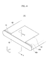
- FIG. 4 is a perspective view illustrating a part of a rechargeable battery according to a second embodiment of the present invention.
- FIG. 5 is a cross-sectional view of the rechargeable battery according to the second embodiment of the present invention.
- the rechargeable battery 102 includes an electrode assembly, a case 60 for housing the electrode assembly, a protective circuit module coupled to the top of the case 60, and a support member 62 coupled to the bottom of the case 60.
- the rechargeable battery 102 according to the present embodiment has the same structure as the rechargeable battery according to the first embodiment, except for a support structure provided at the bottom of the case 60. Thus, repetitive description of the same structure will be omitted.
- the case 60 as a flexible pouch type case, and the case 60 may be made of a synthetic resin film, or a laminate film formed of a synthetic resin film with a metal thin film inserted therein.
- a protrusion 60a and a recess 60b positioned inside the protrusion 60a are formed on the bottom surface of the case 60.
- the protrusion 60a extends downwardly from the case 60 (i.e. away from the second end of the case 60), and extends along the bottom corner of the case 60.
- the protrusion 60a protrudes from three edges of the bottom surface of the case 60, and an opening with no protrusion is formed on one edge of the bottom surface of the case 60.
- the protrusion 60a is formed by bending a film material positioned at the bottom of the case 60. By pressing and flattening the center of the bottom at which a surplus portion is formed, the protrusion 60a is formed, and the recess 60b is formed inside the protrusion 60a.
- a buffer member 61 is inserted into the recess 60b.
- the buffer member 61 is formed in a longitudinal plate-like shape which extends in the lengthwise direction (y-axis direction of FIG. 4 ) of the bottom surface of the case 60.
- the buffer member 61 may be made of polymer which has elasticity so as to absorb an impact.
- the buffer member 61 is a tape with an adhesive layer formed on one surface. Therefore, the buffer member 61 is stably attached to the case 60 and absorbs an impact an impact transferred to the case 60.
- a buffer member 61 can be located between the support member 62 and the second end of the case 60 in other ways, with the buffer member 61 arranged to absorb impacts.
- a finishing tape 63 is attached to the bottom of the buffer member 61 to surround both side surfaces and the bottom surface of the case 60.
- the finishing tape 63 is attached to both of the side surfaces of the case 60 while partially surrounding a center portion of the buffer member 61 thereby stably fixing the buffer member 61.
- the finishing tape 63 can be attached to an outside surface of the case 60 in a different way, with the finishing tape 63 located between the buffer member 61 and the support member 62. Such a finishing tape 63 is arranged to fix the buffer member 61 in place.
- the support member 62 is provided on the bottom of the finishing tape 63.
- the support member 62 is a tape with an adhesive layer formed on one surface.
- the support member 62 is attached to the bottom surfaces of the finishing tape 63 and buffer member 61, and serves to maintain the shape of the case 60 and prevent the movement of the electrode assembly 10 provided within the case 60.
- FIG. 6 is an exploded perspective view illustrating a part of a rechargeable battery according to a third embodiment of the present invention.
- FIG. 7 is a cross-sectional view of the rechargeable battery according to the third embodiment of the present invention.
- the rechargeable battery 103 includes an electrode assembly, a case 70 for housing the electrode assembly, a protective circuit module coupled to the top of the case 70, and a support member 72 coupled to the bottom of the case 70.
- the rechargeable battery 103 according to the present embodiment has the same structure as the rechargeable battery according to the first embodiment, except for a support structure provided at the bottom of the case 70. Thus, repetitive description of the same structure will be omitted.
- the case 70 as a flexible pouch type case, and the case 70 may be made of a synthetic resin film, or a laminate film formed of a synthetic resin film with a metal thin film inserted therein.
- a protrusion and a recess 70b positioned inside the protrusion are formed on the bottom surface of the case 70.
- the protrusion includes a first protrusion formed by being bent from the bottom surface of the case 70 and a second protrusion 70d extending from both longitudinal ends of the first protrusion 70a and extending downwardly (i.e. away from the second end).
- the bottom surface of the case 70 has an approximately rectangular shape.
- the first protrusion 70a is formed on the lengthwise (y-axis directional) edge of the bottom surface of the case 70
- the second protrusion 70d is formed on the widthwise (x-axis directional) edge of the bottom surface of the case 70.
- an opening 70c with no protrusion is formed on one edge of the bottom surface of the case 70.
- the first protrusion 70a and the second protrusion 70d are formed by bending a film material positioned at the bottom of the case 70. By pushing and bending a surplus portion positioned at the bottom of the case 70 in the widthwise direction of the bottom surface, a protruding portion is formed on one edge. By bending the protruding portion, the first protrusion 70a is formed. Moreover, the second protrusion 70d is formed, being connected to both side ends of the first protrusion 70a, by pushing the surplus portion in both lengthwise directions of the bottom surface during the formation of the first protrusion 70a.
- a recess 70b is formed inward of the protrusions.
- a finishing tape 73 is attached to surround both side surfaces and the bottom surface of the case 70.
- the finishing tape 73 is attached to both of the side surfaces of the case 70 while partially surrounding the first protrusion 70a, and then fixed to them such that the first protrusion 70a is kept bent.
- the support member 72 is provided on the bottom of the finishing tape 73.
- the support member 72 is a tape with an adhesive layer formed on one surface.
- the support member 72 is attached to the bottom surfaces of the finishing tape 73 and case 70, and serves to maintain the shape of the case 70 and prevent the movement of the electrode assembly provided within the case 70.
- the first protrusion 70a removes a surplus space, thereby preventing the movement of the electrode assembly.
- the protrusion portion is folded so that one side of the protrusion portion is adjacent the second end of the case, with the support member 72 adjacent an opposite side of the protrusion portion.
- the support member 72 maintains the shape of the case 70.
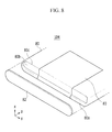
- FIG. 8 is an exploded perspective view illustrating a part of a rechargeable battery according to a third embodiment of the present invention.
- FIG. 9 is a cross-sectional view of the rechargeable battery according to the fourth embodiment of the present invention.
- the rechargeable battery 104 includes an electrode assembly, a case 80 for housing the electrode assembly, a protective circuit module coupled to the top of the case 80, and a support member 82 coupled to the bottom of the case 80.
- the rechargeable battery 104 according to the present embodiment has the same structure as the rechargeable battery according to the first embodiment, except for a support structure provided at the bottom of the case 80. Thus, repetitive description of the same structure will be omitted.
- the case 80 as a flexible pouch type case, and the case 80 may be made of a synthetic resin film, or a laminate film formed of a synthetic resin film with a metal thin film inserted therein.
- a protrusion 80a and a recess 8ob positioned inside the protrusion 80a are formed on the bottom surface of the case 80.
- the protrusion 80a is protruded downward from the case 80, and extends along the bottom edge of the case 80.
- the protrusion 80a is protruded on three edges of the bottom surface of the case 80, and an opening 80c with no protrusion is formed on one edge of the bottom surface of the case 80.
- the protrusion 80a is formed by bending a film material positioned at the bottom of the case 80. By pressing and flattening the center of the bottom at which a surplus portion is formed, the protrusion 80a is formed, and the recess 80b is formed inside the protrusion 80.
- a finishing tape 83 is attached to surround both side surfaces and the bottom surface of the case 80.
- the finishing tape 83 is attached to both of the side surfaces of the case 80 while partially surrounding the protrusion 80a, thereby maintaining the shape of the protrusion 80a.
- the support member 82 is provided on the bottom of the finishing tape 83.
- the support member 82 is a tape with an adhesive layer formed on one surface.
- the support member 82 is attached to the bottom surfaces of the finishing tape 83 and case 80, and serves to maintain the shape of the case 70 and prevent the movement of the electrode assembly provided within the case 80.
- a rechargeable battery that comprises a pouch type case, with an electrode assembly housed within the case. Electrode tabs are connected to the electrode assembly, with the electrode tabs protruding from a first end of the case.
- the battery is arranged such that a second end of the case (e.g. a bottom end of the case) comprises a recessed portion in the second end of the case.
- the battery further comprises a support member adjacent an outer surface of the second end of the case.
- the support member is arranged to maintain a shape of the second end of the case. Hence, the shape of the second end of the pouch type case is maintained by the presence of the support member. Therefore, the second end will be prevented from deforming if the rechargeable battery undergoes shocks, which helps to prevent short circuits.
- the recessed portion is arranged to prevent movement of the electrode assembly within the case.
- the support member comprises is located in the recessed portion, and the support member can comprise a tape.
- the rechargeable battery can further comprise a protective circuit module adjacent the first end of the case, with the protective circuit module connected to the electrode tabs.
- Some embodiments of the invention include a portion of the second end of the case that is folded to form a protrusion portion around at least one edge region of the second end of the case.
- a recessed portion in the second end of the case could be formed without such a protrusion portion.
- the recess could be a broad depression with no distinct protrusion being formed.
- a finishing can be provided that is attached to an outside surface of the case, with the finishing tape being located between the second end of the case and the support member. Such a finishing tape can be provided to keep at least a portion of the protrusion portion folded.
- the rechargeable battery further comprises a buffer member located between the support member and the second end of the case, wherein the buffer member is arranged to absorb impacts.
- the buffer member can be located within the recessed portion, and can comprise a tape.
- a finishing tape can be attached to an outside surface of the case, the finishing tape being located between the buffer member and the support member. Such a finishing tape can fix the buffer member in place.
Landscapes
- Chemical & Material Sciences (AREA)
- Chemical Kinetics & Catalysis (AREA)
- Electrochemistry (AREA)
- General Chemical & Material Sciences (AREA)
- Engineering & Computer Science (AREA)
- Manufacturing & Machinery (AREA)
- Sealing Battery Cases Or Jackets (AREA)
- Battery Mounting, Suspending (AREA)
Applications Claiming Priority (2)
| Application Number | Priority Date | Filing Date | Title |
|---|---|---|---|
| US201261663869P | 2012-06-25 | 2012-06-25 | |
| US13/670,582 US9431636B2 (en) | 2012-06-25 | 2012-11-07 | Rechargeable battery |
Publications (2)
| Publication Number | Publication Date |
|---|---|
| EP2680337A1 true EP2680337A1 (fr) | 2014-01-01 |
| EP2680337B1 EP2680337B1 (fr) | 2017-06-07 |
Family
ID=47257539
Family Applications (1)
| Application Number | Title | Priority Date | Filing Date |
|---|---|---|---|
| EP12193756.9A Active EP2680337B1 (fr) | 2012-06-25 | 2012-11-22 | Batterie rechargeable |
Country Status (4)
| Country | Link |
|---|---|
| US (1) | US9431636B2 (fr) |
| EP (1) | EP2680337B1 (fr) |
| KR (1) | KR102018692B1 (fr) |
| CN (1) | CN103515555B (fr) |
Families Citing this family (8)
| Publication number | Priority date | Publication date | Assignee | Title |
|---|---|---|---|---|
| USD687777S1 (en) * | 2012-05-24 | 2013-08-13 | Sony Corporation | Rechargeable battery |
| KR102222113B1 (ko) * | 2014-07-14 | 2021-03-03 | 삼성에스디아이 주식회사 | 가요성 이차 전지 |
| KR102246995B1 (ko) | 2014-10-24 | 2021-04-29 | 에스케이이노베이션 주식회사 | 외부 지지체가 장착된 전극 조립체를 포함하는 리튬 이차 전지 |
| TWI721188B (zh) * | 2016-07-06 | 2021-03-11 | 日商藤森工業股份有限公司 | 電池外裝體、電池組及電池裝置 |
| KR102119183B1 (ko) * | 2016-08-18 | 2020-06-04 | 주식회사 엘지화학 | 배터리 모듈 |
| WO2019196073A1 (fr) * | 2018-04-12 | 2019-10-17 | 宁德新能源科技有限公司 | Batterie |
| DE102019112219A1 (de) * | 2019-05-10 | 2020-11-12 | Johnson Controls Autobatterie Gmbh & Co. Kgaa | Batteriegehäuse und Batterie mit einem solchen |
| KR102936714B1 (ko) * | 2022-01-13 | 2026-03-09 | 주식회사 엘지에너지솔루션 | 충격 흡수 기능을 구비한 전지 팩 어셈블리, 이의 제조장치 및 제조방법 |
Citations (5)
| Publication number | Priority date | Publication date | Assignee | Title |
|---|---|---|---|---|
| EP1760803A1 (fr) * | 2005-09-02 | 2007-03-07 | Sony Corporation | Accumulateur |
| EP1772914A2 (fr) * | 2005-09-28 | 2007-04-11 | Samsung SDI Co., Ltd. | Batterie secondaire au lithium de type poche et méthode de sa fabrication |
| US20100297494A1 (en) * | 2009-05-21 | 2010-11-25 | Chin-Ming Chen | Battery module |
| DE102009037726A1 (de) * | 2009-08-17 | 2011-02-24 | Li-Tec Battery Gmbh | Galvanische Zelle mit Rahmen und Verfahren zu ihrer Herstellung |
| US20110183189A1 (en) * | 2010-01-25 | 2011-07-28 | Gm Global Technology Operations, Inc. | Extended range electric vehicle battery cell packaging for pouch design |
Family Cites Families (6)
| Publication number | Priority date | Publication date | Assignee | Title |
|---|---|---|---|---|
| KR100731437B1 (ko) * | 2005-11-29 | 2007-06-21 | 삼성에스디아이 주식회사 | 파우치형 리튬 이차 전지 |
| KR100839785B1 (ko) * | 2005-12-29 | 2008-06-19 | 삼성에스디아이 주식회사 | 이차전지 및 그 형성 방법 |
| KR100788553B1 (ko) | 2006-02-27 | 2007-12-26 | 삼성에스디아이 주식회사 | 리튬 이차전지용 캔 및 이를 이용한 리튬 이차전지 |
| KR101318569B1 (ko) | 2006-08-17 | 2013-10-16 | 삼성에스디아이 주식회사 | 이차 전지 |
| KR100947972B1 (ko) * | 2007-12-14 | 2010-03-15 | 삼성에스디아이 주식회사 | 배터리 팩 |
| KR101030856B1 (ko) * | 2008-12-16 | 2011-04-22 | 삼성에스디아이 주식회사 | 배터리 팩 |
-
2012
- 2012-11-07 US US13/670,582 patent/US9431636B2/en active Active
- 2012-11-22 EP EP12193756.9A patent/EP2680337B1/fr active Active
-
2013
- 2013-06-21 KR KR1020130071846A patent/KR102018692B1/ko active Active
- 2013-06-25 CN CN201310256038.0A patent/CN103515555B/zh active Active
Patent Citations (5)
| Publication number | Priority date | Publication date | Assignee | Title |
|---|---|---|---|---|
| EP1760803A1 (fr) * | 2005-09-02 | 2007-03-07 | Sony Corporation | Accumulateur |
| EP1772914A2 (fr) * | 2005-09-28 | 2007-04-11 | Samsung SDI Co., Ltd. | Batterie secondaire au lithium de type poche et méthode de sa fabrication |
| US20100297494A1 (en) * | 2009-05-21 | 2010-11-25 | Chin-Ming Chen | Battery module |
| DE102009037726A1 (de) * | 2009-08-17 | 2011-02-24 | Li-Tec Battery Gmbh | Galvanische Zelle mit Rahmen und Verfahren zu ihrer Herstellung |
| US20110183189A1 (en) * | 2010-01-25 | 2011-07-28 | Gm Global Technology Operations, Inc. | Extended range electric vehicle battery cell packaging for pouch design |
Also Published As
| Publication number | Publication date |
|---|---|
| KR102018692B1 (ko) | 2019-09-06 |
| US20130344380A1 (en) | 2013-12-26 |
| EP2680337B1 (fr) | 2017-06-07 |
| CN103515555B (zh) | 2018-04-24 |
| US9431636B2 (en) | 2016-08-30 |
| KR20140004003A (ko) | 2014-01-10 |
| CN103515555A (zh) | 2014-01-15 |
Similar Documents
| Publication | Publication Date | Title |
|---|---|---|
| EP2680337B1 (fr) | Batterie rechargeable | |
| US10490781B2 (en) | Rechargeable battery having corner folding portion | |
| JP6730431B2 (ja) | バッテリーモジュール及びそれを含むバッテリーパック、自動車 | |
| US9083040B2 (en) | Rechargeable battery pack | |
| US9917290B2 (en) | Battery module having holder | |
| US10388918B2 (en) | Secondary battery | |
| US20150037619A1 (en) | Rechargeable battery pack | |
| EP2672543B1 (fr) | Bloc-batterie rechargeable | |
| EP2958180A1 (fr) | Élément de batterie présentant une structure nouvelle et une sécurité améliorée | |
| US12034128B2 (en) | Battery pack | |
| US9871274B2 (en) | Secondary battery with protection circuit module with label and release sheet | |
| US20160036015A1 (en) | Rechargeable battery having edge bonding portion | |
| KR20160123851A (ko) | 홀더를 갖는 전지 모듈 | |
| US20230216157A1 (en) | Secondary battery | |
| KR102505609B1 (ko) | 전지 팩 | |
| US9123933B2 (en) | Rechargeable battery pack | |
| US20160372735A1 (en) | Rechargeable battery having current collector | |
| EP3128569A1 (fr) | Batterie secondaire | |
| US11024929B2 (en) | Battery pack including release cover | |
| US20140255731A1 (en) | Rechargeable battery pack | |
| KR20190005405A (ko) | 배터리 모듈 | |
| JP2025517191A (ja) | 耐衝撃性に優れたバッテリーパック |
Legal Events
| Date | Code | Title | Description |
|---|---|---|---|
| PUAI | Public reference made under article 153(3) epc to a published international application that has entered the european phase |
Free format text: ORIGINAL CODE: 0009012 |
|
| AK | Designated contracting states |
Kind code of ref document: A1 Designated state(s): AL AT BE BG CH CY CZ DE DK EE ES FI FR GB GR HR HU IE IS IT LI LT LU LV MC MK MT NL NO PL PT RO RS SE SI SK SM TR |
|
| AX | Request for extension of the european patent |
Extension state: BA ME |
|
| 17P | Request for examination filed |
Effective date: 20140701 |
|
| RBV | Designated contracting states (corrected) |
Designated state(s): AL AT BE BG CH CY CZ DE DK EE ES FI FR GB GR HR HU IE IS IT LI LT LU LV MC MK MT NL NO PL PT RO RS SE SI SK SM TR |
|
| 17Q | First examination report despatched |
Effective date: 20150112 |
|
| GRAP | Despatch of communication of intention to grant a patent |
Free format text: ORIGINAL CODE: EPIDOSNIGR1 |
|
| STAA | Information on the status of an ep patent application or granted ep patent |
Free format text: STATUS: GRANT OF PATENT IS INTENDED |
|
| RIC1 | Information provided on ipc code assigned before grant |
Ipc: H01M 10/052 20100101ALN20161124BHEP Ipc: H01M 2/02 20060101AFI20161124BHEP |
|
| INTG | Intention to grant announced |
Effective date: 20161212 |
|
| GRAS | Grant fee paid |
Free format text: ORIGINAL CODE: EPIDOSNIGR3 |
|
| GRAA | (expected) grant |
Free format text: ORIGINAL CODE: 0009210 |
|
| STAA | Information on the status of an ep patent application or granted ep patent |
Free format text: STATUS: THE PATENT HAS BEEN GRANTED |
|
| RAP1 | Party data changed (applicant data changed or rights of an application transferred) |
Owner name: SAMSUNG SDI CO., LTD. |
|
| AK | Designated contracting states |
Kind code of ref document: B1 Designated state(s): AL AT BE BG CH CY CZ DE DK EE ES FI FR GB GR HR HU IE IS IT LI LT LU LV MC MK MT NL NO PL PT RO RS SE SI SK SM TR |
|
| REG | Reference to a national code |
Ref country code: GB Ref legal event code: FG4D |
|
| GRAA | (expected) grant |
Free format text: ORIGINAL CODE: 0009210 |
|
| REG | Reference to a national code |
Ref country code: CH Ref legal event code: EP Ref country code: AT Ref legal event code: REF Ref document number: 899819 Country of ref document: AT Kind code of ref document: T Effective date: 20170615 |
|
| REG | Reference to a national code |
Ref country code: IE Ref legal event code: FG4D |
|
| REG | Reference to a national code |
Ref country code: DE Ref legal event code: R096 Ref document number: 602012033177 Country of ref document: DE |
|
| REG | Reference to a national code |
Ref country code: NL Ref legal event code: MP Effective date: 20170607 |
|
| REG | Reference to a national code |
Ref country code: LT Ref legal event code: MG4D |
|
| REG | Reference to a national code |
Ref country code: FR Ref legal event code: PLFP Year of fee payment: 6 |
|
| PG25 | Lapsed in a contracting state [announced via postgrant information from national office to epo] |
Ref country code: ES Free format text: LAPSE BECAUSE OF FAILURE TO SUBMIT A TRANSLATION OF THE DESCRIPTION OR TO PAY THE FEE WITHIN THE PRESCRIBED TIME-LIMIT Effective date: 20170607 Ref country code: NO Free format text: LAPSE BECAUSE OF FAILURE TO SUBMIT A TRANSLATION OF THE DESCRIPTION OR TO PAY THE FEE WITHIN THE PRESCRIBED TIME-LIMIT Effective date: 20170907 Ref country code: FI Free format text: LAPSE BECAUSE OF FAILURE TO SUBMIT A TRANSLATION OF THE DESCRIPTION OR TO PAY THE FEE WITHIN THE PRESCRIBED TIME-LIMIT Effective date: 20170607 Ref country code: HR Free format text: LAPSE BECAUSE OF FAILURE TO SUBMIT A TRANSLATION OF THE DESCRIPTION OR TO PAY THE FEE WITHIN THE PRESCRIBED TIME-LIMIT Effective date: 20170607 Ref country code: GR Free format text: LAPSE BECAUSE OF FAILURE TO SUBMIT A TRANSLATION OF THE DESCRIPTION OR TO PAY THE FEE WITHIN THE PRESCRIBED TIME-LIMIT Effective date: 20170908 Ref country code: LT Free format text: LAPSE BECAUSE OF FAILURE TO SUBMIT A TRANSLATION OF THE DESCRIPTION OR TO PAY THE FEE WITHIN THE PRESCRIBED TIME-LIMIT Effective date: 20170607 |
|
| REG | Reference to a national code |
Ref country code: AT Ref legal event code: MK05 Ref document number: 899819 Country of ref document: AT Kind code of ref document: T Effective date: 20170607 |
|
| PG25 | Lapsed in a contracting state [announced via postgrant information from national office to epo] |
Ref country code: NL Free format text: LAPSE BECAUSE OF FAILURE TO SUBMIT A TRANSLATION OF THE DESCRIPTION OR TO PAY THE FEE WITHIN THE PRESCRIBED TIME-LIMIT Effective date: 20170607 Ref country code: BG Free format text: LAPSE BECAUSE OF FAILURE TO SUBMIT A TRANSLATION OF THE DESCRIPTION OR TO PAY THE FEE WITHIN THE PRESCRIBED TIME-LIMIT Effective date: 20170907 Ref country code: RS Free format text: LAPSE BECAUSE OF FAILURE TO SUBMIT A TRANSLATION OF THE DESCRIPTION OR TO PAY THE FEE WITHIN THE PRESCRIBED TIME-LIMIT Effective date: 20170607 Ref country code: SE Free format text: LAPSE BECAUSE OF FAILURE TO SUBMIT A TRANSLATION OF THE DESCRIPTION OR TO PAY THE FEE WITHIN THE PRESCRIBED TIME-LIMIT Effective date: 20170607 Ref country code: LV Free format text: LAPSE BECAUSE OF FAILURE TO SUBMIT A TRANSLATION OF THE DESCRIPTION OR TO PAY THE FEE WITHIN THE PRESCRIBED TIME-LIMIT Effective date: 20170607 |
|
| PG25 | Lapsed in a contracting state [announced via postgrant information from national office to epo] |
Ref country code: RO Free format text: LAPSE BECAUSE OF FAILURE TO SUBMIT A TRANSLATION OF THE DESCRIPTION OR TO PAY THE FEE WITHIN THE PRESCRIBED TIME-LIMIT Effective date: 20170607 Ref country code: CZ Free format text: LAPSE BECAUSE OF FAILURE TO SUBMIT A TRANSLATION OF THE DESCRIPTION OR TO PAY THE FEE WITHIN THE PRESCRIBED TIME-LIMIT Effective date: 20170607 Ref country code: EE Free format text: LAPSE BECAUSE OF FAILURE TO SUBMIT A TRANSLATION OF THE DESCRIPTION OR TO PAY THE FEE WITHIN THE PRESCRIBED TIME-LIMIT Effective date: 20170607 Ref country code: AT Free format text: LAPSE BECAUSE OF FAILURE TO SUBMIT A TRANSLATION OF THE DESCRIPTION OR TO PAY THE FEE WITHIN THE PRESCRIBED TIME-LIMIT Effective date: 20170607 Ref country code: SK Free format text: LAPSE BECAUSE OF FAILURE TO SUBMIT A TRANSLATION OF THE DESCRIPTION OR TO PAY THE FEE WITHIN THE PRESCRIBED TIME-LIMIT Effective date: 20170607 |
|
| PG25 | Lapsed in a contracting state [announced via postgrant information from national office to epo] |
Ref country code: SM Free format text: LAPSE BECAUSE OF FAILURE TO SUBMIT A TRANSLATION OF THE DESCRIPTION OR TO PAY THE FEE WITHIN THE PRESCRIBED TIME-LIMIT Effective date: 20170607 Ref country code: PL Free format text: LAPSE BECAUSE OF FAILURE TO SUBMIT A TRANSLATION OF THE DESCRIPTION OR TO PAY THE FEE WITHIN THE PRESCRIBED TIME-LIMIT Effective date: 20170607 Ref country code: IT Free format text: LAPSE BECAUSE OF FAILURE TO SUBMIT A TRANSLATION OF THE DESCRIPTION OR TO PAY THE FEE WITHIN THE PRESCRIBED TIME-LIMIT Effective date: 20170607 Ref country code: IS Free format text: LAPSE BECAUSE OF FAILURE TO SUBMIT A TRANSLATION OF THE DESCRIPTION OR TO PAY THE FEE WITHIN THE PRESCRIBED TIME-LIMIT Effective date: 20171007 |
|
| REG | Reference to a national code |
Ref country code: DE Ref legal event code: R097 Ref document number: 602012033177 Country of ref document: DE |
|
| PLBE | No opposition filed within time limit |
Free format text: ORIGINAL CODE: 0009261 |
|
| STAA | Information on the status of an ep patent application or granted ep patent |
Free format text: STATUS: NO OPPOSITION FILED WITHIN TIME LIMIT |
|
| PG25 | Lapsed in a contracting state [announced via postgrant information from national office to epo] |
Ref country code: DK Free format text: LAPSE BECAUSE OF FAILURE TO SUBMIT A TRANSLATION OF THE DESCRIPTION OR TO PAY THE FEE WITHIN THE PRESCRIBED TIME-LIMIT Effective date: 20170607 |
|
| 26N | No opposition filed |
Effective date: 20180308 |
|
| PG25 | Lapsed in a contracting state [announced via postgrant information from national office to epo] |
Ref country code: SI Free format text: LAPSE BECAUSE OF FAILURE TO SUBMIT A TRANSLATION OF THE DESCRIPTION OR TO PAY THE FEE WITHIN THE PRESCRIBED TIME-LIMIT Effective date: 20170607 |
|
| PG25 | Lapsed in a contracting state [announced via postgrant information from national office to epo] |
Ref country code: MC Free format text: LAPSE BECAUSE OF FAILURE TO SUBMIT A TRANSLATION OF THE DESCRIPTION OR TO PAY THE FEE WITHIN THE PRESCRIBED TIME-LIMIT Effective date: 20170607 |
|
| PG25 | Lapsed in a contracting state [announced via postgrant information from national office to epo] |
Ref country code: CH Free format text: LAPSE BECAUSE OF NON-PAYMENT OF DUE FEES Effective date: 20171130 Ref country code: LI Free format text: LAPSE BECAUSE OF NON-PAYMENT OF DUE FEES Effective date: 20171130 |
|
| PG25 | Lapsed in a contracting state [announced via postgrant information from national office to epo] |
Ref country code: LU Free format text: LAPSE BECAUSE OF NON-PAYMENT OF DUE FEES Effective date: 20171122 |
|
| REG | Reference to a national code |
Ref country code: BE Ref legal event code: MM Effective date: 20171130 |
|
| REG | Reference to a national code |
Ref country code: IE Ref legal event code: MM4A |
|
| PG25 | Lapsed in a contracting state [announced via postgrant information from national office to epo] |
Ref country code: MT Free format text: LAPSE BECAUSE OF NON-PAYMENT OF DUE FEES Effective date: 20171122 |
|
| REG | Reference to a national code |
Ref country code: FR Ref legal event code: PLFP Year of fee payment: 7 |
|
| PG25 | Lapsed in a contracting state [announced via postgrant information from national office to epo] |
Ref country code: IE Free format text: LAPSE BECAUSE OF NON-PAYMENT OF DUE FEES Effective date: 20171122 |
|
| PG25 | Lapsed in a contracting state [announced via postgrant information from national office to epo] |
Ref country code: BE Free format text: LAPSE BECAUSE OF NON-PAYMENT OF DUE FEES Effective date: 20171130 |
|
| PG25 | Lapsed in a contracting state [announced via postgrant information from national office to epo] |
Ref country code: HU Free format text: LAPSE BECAUSE OF FAILURE TO SUBMIT A TRANSLATION OF THE DESCRIPTION OR TO PAY THE FEE WITHIN THE PRESCRIBED TIME-LIMIT; INVALID AB INITIO Effective date: 20121122 |
|
| PG25 | Lapsed in a contracting state [announced via postgrant information from national office to epo] |
Ref country code: CY Free format text: LAPSE BECAUSE OF NON-PAYMENT OF DUE FEES Effective date: 20170607 |
|
| PG25 | Lapsed in a contracting state [announced via postgrant information from national office to epo] |
Ref country code: MK Free format text: LAPSE BECAUSE OF FAILURE TO SUBMIT A TRANSLATION OF THE DESCRIPTION OR TO PAY THE FEE WITHIN THE PRESCRIBED TIME-LIMIT Effective date: 20170607 |
|
| PG25 | Lapsed in a contracting state [announced via postgrant information from national office to epo] |
Ref country code: TR Free format text: LAPSE BECAUSE OF FAILURE TO SUBMIT A TRANSLATION OF THE DESCRIPTION OR TO PAY THE FEE WITHIN THE PRESCRIBED TIME-LIMIT Effective date: 20170607 |
|
| PG25 | Lapsed in a contracting state [announced via postgrant information from national office to epo] |
Ref country code: PT Free format text: LAPSE BECAUSE OF FAILURE TO SUBMIT A TRANSLATION OF THE DESCRIPTION OR TO PAY THE FEE WITHIN THE PRESCRIBED TIME-LIMIT Effective date: 20170607 |
|
| PG25 | Lapsed in a contracting state [announced via postgrant information from national office to epo] |
Ref country code: AL Free format text: LAPSE BECAUSE OF FAILURE TO SUBMIT A TRANSLATION OF THE DESCRIPTION OR TO PAY THE FEE WITHIN THE PRESCRIBED TIME-LIMIT Effective date: 20170607 |
|
| REG | Reference to a national code |
Ref country code: DE Ref legal event code: R079 Ref document number: 602012033177 Country of ref document: DE Free format text: PREVIOUS MAIN CLASS: H01M0002020000 Ipc: H01M0050100000 |
|
| P01 | Opt-out of the competence of the unified patent court (upc) registered |
Effective date: 20230528 |
|
| PGFP | Annual fee paid to national office [announced via postgrant information from national office to epo] |
Ref country code: DE Payment date: 20251104 Year of fee payment: 14 |
|
| PGFP | Annual fee paid to national office [announced via postgrant information from national office to epo] |
Ref country code: GB Payment date: 20251030 Year of fee payment: 14 |
|
| PGFP | Annual fee paid to national office [announced via postgrant information from national office to epo] |
Ref country code: FR Payment date: 20251117 Year of fee payment: 14 |