EP2680412A2 - Agencement de fils de bobine dans un rotor de moteur électrique - Google Patents
Agencement de fils de bobine dans un rotor de moteur électrique Download PDFInfo
- Publication number
- EP2680412A2 EP2680412A2 EP13173851.0A EP13173851A EP2680412A2 EP 2680412 A2 EP2680412 A2 EP 2680412A2 EP 13173851 A EP13173851 A EP 13173851A EP 2680412 A2 EP2680412 A2 EP 2680412A2
- Authority
- EP
- European Patent Office
- Prior art keywords
- armature
- coil
- switching
- wires
- cavity
- Prior art date
- Legal status (The legal status is an assumption and is not a legal conclusion. Google has not performed a legal analysis and makes no representation as to the accuracy of the status listed.)
- Granted
Links
Images


Classifications
-
- H—ELECTRICITY
- H02—GENERATION; CONVERSION OR DISTRIBUTION OF ELECTRIC POWER
- H02K—DYNAMO-ELECTRIC MACHINES
- H02K1/00—Details of the magnetic circuit
- H02K1/06—Details of the magnetic circuit characterised by the shape, form or construction
- H02K1/22—Rotating parts of the magnetic circuit
-
- H—ELECTRICITY
- H02—GENERATION; CONVERSION OR DISTRIBUTION OF ELECTRIC POWER
- H02K—DYNAMO-ELECTRIC MACHINES
- H02K1/00—Details of the magnetic circuit
- H02K1/06—Details of the magnetic circuit characterised by the shape, form or construction
- H02K1/22—Rotating parts of the magnetic circuit
- H02K1/26—Rotor cores with slots for windings
- H02K1/265—Shape, form or location of the slots
-
- H—ELECTRICITY
- H02—GENERATION; CONVERSION OR DISTRIBUTION OF ELECTRIC POWER
- H02K—DYNAMO-ELECTRIC MACHINES
- H02K1/00—Details of the magnetic circuit
- H02K1/06—Details of the magnetic circuit characterised by the shape, form or construction
- H02K1/12—Stationary parts of the magnetic circuit
- H02K1/16—Stator cores with slots for windings
- H02K1/165—Shape, form or location of the slots
-
- H—ELECTRICITY
- H02—GENERATION; CONVERSION OR DISTRIBUTION OF ELECTRIC POWER
- H02K—DYNAMO-ELECTRIC MACHINES
- H02K13/00—Structural associations of current collectors with motors or generators, e.g. brush mounting plates or connections to windings; Disposition of current collectors in motors or generators; Arrangements for improving commutation
- H02K13/04—Connections between commutator segments and windings
-
- H—ELECTRICITY
- H02—GENERATION; CONVERSION OR DISTRIBUTION OF ELECTRIC POWER
- H02K—DYNAMO-ELECTRIC MACHINES
- H02K15/00—Processes or apparatus specially adapted for manufacturing, assembling, maintaining or repairing of dynamo-electric machines
- H02K15/20—Shaping or compacting conductors or winding heads after the installation of the winding in the cores or machines; Applying fastening means on winding heads
- H02K15/22—Shaping or compacting conductors in slots or around salient poles
-
- H—ELECTRICITY
- H02—GENERATION; CONVERSION OR DISTRIBUTION OF ELECTRIC POWER
- H02K—DYNAMO-ELECTRIC MACHINES
- H02K23/00—DC commutator motors or generators having mechanical commutator; Universal AC/DC commutator motors
-
- H—ELECTRICITY
- H02—GENERATION; CONVERSION OR DISTRIBUTION OF ELECTRIC POWER
- H02K—DYNAMO-ELECTRIC MACHINES
- H02K23/00—DC commutator motors or generators having mechanical commutator; Universal AC/DC commutator motors
- H02K23/26—DC commutator motors or generators having mechanical commutator; Universal AC/DC commutator motors characterised by the armature windings
- H02K23/30—DC commutator motors or generators having mechanical commutator; Universal AC/DC commutator motors characterised by the armature windings having lap or loop windings
-
- H—ELECTRICITY
- H02—GENERATION; CONVERSION OR DISTRIBUTION OF ELECTRIC POWER
- H02K—DYNAMO-ELECTRIC MACHINES
- H02K3/00—Details of windings
- H02K3/04—Windings characterised by the conductor shape, form or construction, e.g. with bar conductors
- H02K3/12—Windings characterised by the conductor shape, form or construction, e.g. with bar conductors arranged in slots
-
- H—ELECTRICITY
- H02—GENERATION; CONVERSION OR DISTRIBUTION OF ELECTRIC POWER
- H02K—DYNAMO-ELECTRIC MACHINES
- H02K3/00—Details of windings
- H02K3/46—Fastening of windings on the stator or rotor structure
-
- H—ELECTRICITY
- H02—GENERATION; CONVERSION OR DISTRIBUTION OF ELECTRIC POWER
- H02K—DYNAMO-ELECTRIC MACHINES
- H02K3/00—Details of windings
- H02K3/04—Windings characterised by the conductor shape, form or construction, e.g. with bar conductors
- H02K3/28—Layout of windings or of connections between windings
-
- H—ELECTRICITY
- H02—GENERATION; CONVERSION OR DISTRIBUTION OF ELECTRIC POWER
- H02K—DYNAMO-ELECTRIC MACHINES
- H02K3/00—Details of windings
- H02K3/32—Windings characterised by the shape, form or construction of the insulation
- H02K3/325—Windings characterised by the shape, form or construction of the insulation for windings on salient poles, such as claw-shaped poles
-
- Y—GENERAL TAGGING OF NEW TECHNOLOGICAL DEVELOPMENTS; GENERAL TAGGING OF CROSS-SECTIONAL TECHNOLOGIES SPANNING OVER SEVERAL SECTIONS OF THE IPC; TECHNICAL SUBJECTS COVERED BY FORMER USPC CROSS-REFERENCE ART COLLECTIONS [XRACs] AND DIGESTS
- Y10—TECHNICAL SUBJECTS COVERED BY FORMER USPC
- Y10T—TECHNICAL SUBJECTS COVERED BY FORMER US CLASSIFICATION
- Y10T29/00—Metal working
- Y10T29/49—Method of mechanical manufacture
- Y10T29/49002—Electrical device making
- Y10T29/49009—Dynamoelectric machine
Definitions
- the present disclosure relates to electric motors.
- the present disclosure relates in particular to armatures for electric motors and to the arrangement of switching wires and of coil wires on the armature.
- Armatures of brushed electric motors comprise coils wound around the teeth of the armature for providing the required magnetization of the teeth of the armature. Magnetisation of the teeth is done by applying an electric current through the coil.
- the coils are electrically contacted via brushes and a commutator in a general known manner. While an electric motor has at least two coils and two teeth, modem electric motors have a plurality of teeth such as for example four or more teeth.
- a coil is wound around each tooth or a plurality of teeth and individually addressed via the commutator.
- the armature may be seen as having a plurality of teeth arranged around the shaft, the armature can also be considered as having a plurality of cavities arranged between the teeth of the armature.
- the coil wires so called switching wires are arranged in the cavities between the teeth.
- the switching wires are used to connect the coils with the commutator and to electrically equalize single bars of the commutator.
- the arrangement of the coil wires and the switching wires with respect to each other depends on the manufacturing method or sequence.
- the arrangement of the switching wire and the coil is different depending on whether the switching wire is placed prior to or after the arrangement of the coil. This has the disadvantage that the position of the coil wires and the coil cannot be determined precisely and manufacturing sequence has to be considered.
- the switching wires will be arranged at the positions where coils are supposed to be arranged, so it is difficult to wind coils on teeth orderly, which will have several negative effects like uncontrolled wire crossings, increased end turn height, unbalance and efficiency degradation of motor.
- the present invention suggests an armature for electric motor, an electric motor with such an armature, and a method for the manufacture thereof.
- the armature comprises a plurality of teeth and a plurality of cavities or slots. Each one of the cavities is arranged in the outer circumferential surface. The cavities are arranged between two of the plurality of teeth, thus forming the armature. At least one of the plurality of cavities is configured and arranged for receiving coil windings adjacent to a wall portion of the at least one cavity/tooth. The wall portion may be a wall of one of the plurality of teeth. At least one of the plurality of cavities comprises a switching wire receptor. The wire receptor is formed by a recess for receiving a switching wire or a plurality of wires.
- the switching wire receptor in the cavity or between the teeth may be used to place, guide and/or support the switching wire in a predetermined position. This allows placing the switching wires as well as the coil wires more precisely which reduces unbalanced mass of the armature and manufacturing of the coils and the armature is made easier. It is also possible to construct coils and armatures without crossing wires as the switching wires are arranged separately in the switching wire receptor which allows reducing the size, i.e. the radius of the armature. The invention helps in designing smaller and more lightweight motors.
- the switching wire receptor may have the form of a recess or groove in a wall portion of the cavity.
- the recess may be formed in the radial innermost surface or at the bottom of the cavity.
- the recess may be large enough to take up one or a plurality of switching wires and to keep the switching wires in place.
- the cross section of the recess or groove may thus be in the same order of magnitude as the diameter of the switching wire or a plurality of switching wires.
- the switching wire receptor may also have a different shape, such as for example a clamp or a wire holder placed in the cavity.
- the switching wire receptor may have a guiding surface for maintaining and supporting the switching wire in a circumferential direction.
- One or two recesses may be provided and two switching wires may be arranged in one switching wire receptor together or separate switching wire receptors may be provided for each switching wire.
- the present disclosure also relates to a method for manufacturing a rotor or armature for an electric motor.
- the method comprises arranging electrical wires on an armature of an electric motor.
- the method comprises placing at least one switching wire in a switching wire receptor arranged in a cavity of the armature.
- the cavity is formed between two teeth of the armature.
- the method further comprises winding coil wires on a coil guiding surface of the at least one cavity.
- the coil guiding surface may be a wall portion of the cavity and may be formed by one of the plurality of teeth.
- the placing of the at least one switching wire in the switching wire receptor arranged in the cavity of the armature may be performed prior to or after the winding the coil wires on the coil guiding surface of the at least one cavity.
- the final position of the coil wires remains the same in both cases, i.e. the order of manufacturing has no influence on the position of the coil wires on the teeth and in the cavities, which makes coils formed with the coil wires wound orderly on the teeth.
- orderly wound coil wires can reduce the resistance of the coils, which improves the efficiency of the motor.
- the placing of the at least one switching wire and the winding can be done in any sequence without changing the outcome.
- the placing of the at least one switching wire may be done prior to the winding of the coil of coil wires in a first cavity and the placing of the at least one switching wire is done prior or subsequently to the winding the coil of coil wires in a first cavity.
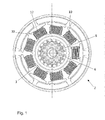
- Fig. 1 shows the cross section of a conventional electric motor with an armature.
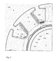
- Fig. 2 shows a portion of a cross section of the conventional armature.
- Fig. 3 shows the same portion of a cross section of an armature according to the first embodiment of the present invention.
- Fig. 4 shows the same portion of a cross section of an armature according to the second embodiment of the present invention.
- Fig. 1 shows an electric motor 2 in which the present invention may be implemented.
- the electric motor may be a conventional electric motor and comprises a rotor 3 with an armature 10 arranged on a rotating shaft 8.
- a commutator 6 with a plurality of contact elements also placed on the rotating shaft 8 in a usual manner.
- the armature 10 comprises a plurality of teeth 12 that are arranged around the rotational axis of the shaft 8.
- the teeth 12 may have a mushroom like shape and may be made from a magnetisable material as known in the art. All parts of the electric motor that are not specifically mentioned herein may be as in any electric motor known in the art.
- Fig. 2 shows a portion of a cross section of the conventional armature. At least one coil of coil wires 30 is wound around each tooth 12 for magnetising the magnetisable material of the teeth 12.
- the coil may be wound directly on the coated teeth 12, or the coil may be wound on an insulator, which is arranged on the surface of the teeth 12.
- Each tooth 12 has two substantial parallel guiding wall portions 13 for winding the coil wires (As shown in Fig. 2 ).
- These guiding wall portions 13 also form a wall portion of the cavities arranged on both sides of the teeth 12 in the circumferential direction.
- the cavities further include a radial innermost wall portion 14 arranged between the guiding wall portions 13 and extending in the circumferential direction.
- the coil wires 30 are connected by switching wires 41, 42 to selected contacts of the commutator to magnetize the corresponding tooth in a predetermined manner during rotation of the rotor 3.
- the switching wires 41, 42 may be terminal end portions of the coil wires 30 and may be made from the same material as the coil wires.
- the switching wires 41, 42 may have the same or a different diameter of cross section compared to the coil wires 30
- the switching wires 41, 42 are also arranged somewhere in the cavities 24 between two teeth 12 as show in Fig. 2 .
- the position of the switching wires 41, 42 in the cavity will depend on the order or sequence of the manufacturing steps. If the coil wires 30 are wound around the tooth 12 prior to placing the switching wire 41, the switching wire 41 is arranged on top of the coil wires as shown on the left hand side of Fig. 2 . If the switching wire 42 is placed in the cavity prior to winding the coil wires 30, the switching wire 42 is placed differently. In this case the switching wire 42 is arranged directly at the guiding wall portion 13 of the cavity 20 and the coil wires 30 are wound on top of the switching wire 42 (not shown). This arrangement of the switching wire 42 is shown on the right hand side of cavity 20 in Fig. 2 .
- the position of the switching wire 41, 42 and consequently the position of the coil wires 30 depends on the sequence in manufacturing, i.e. if the switching wire 41, 42 is placed prior to or after winding the coil wires.
- the manufacturing sequence has to be considered in manufacturing making manufacturing of the armature complex. If the manufacturing sequence was not considered, in some cavities 24 the switching wires 42 will be arranged at the positions where coils are supposed to be arranged, so it is difficult to wind coils on teeth 12 orderly, which will have several negative effects like uncontrolled wire crossings, increased end turn height, unbalance and efficiency degradation of motor. And even the manufacturing sequence is considered, it is also difficult to wind coils on teeth 12 orderly because the switching wires 41, 42 can move easily, especially when the rotor 3 is rotating. And disorderly wound coil wires 30 will increase the resistance of the coils and reduce the efficiency of the motor.
- Fig. 3 shows the same section of an armature 100 as Fig. 2 for armature 10.
- the armature 100 of Figure 3 provides a groove or recess 240 at the radially innermost wall portion 140 of the cavity or slot 200.
- the groove or recess 240 may have the form of channels in which switching wires 410 and 420 are positioned, guided and maintained in place.
- the recess 240 is arranged at the radial innermost wall portion 140 so that the space to wind coils 30 will not be affected.
- the switching wires 410 and 420 are thus well separated from the coil wires 30 and can be placed in the groove or recess 240 prior or after winding the coil 30 around the teeth 12.
- the switching wires 410 and 420 and the coil wire 30 are always placed in the same position, independent of the manufacturing sequence. This enables a more precise arrangement of the coil wire 30 and of the switching wires 410 and 420 and the manufacturing process can be made more flexible.
- the armature 100 can be designed more compact and a smaller diameter of the armature may be achieved leading to smaller and more lightweight motors.
- the magnetic field in the teeth 12 can be generated more precisely and the unbalanced mass flyweight of the armature 10 can be reduced.
- coil wires can be wound around teeth orderly, which can reduce the resistance of the coils and improve the efficiency of the motor
- the recess 240 has a depth corresponding to the diameter of the switching wires 410 and 420.
- the recess 240 may have a depth larger than the diameter of the switching wires 410 and 420, or at least larger than half of the diameter of the switching wires 410 and 420.
- the recess 240 with a depth corresponding to or larger than the diameter of the switching wires 410 and 420 can make sure the switching wires 410 and 420 hold in the recess 240.
- the cross sectional shape of the recess may comprise a bottom portion 244 and a first wall portion 241 and a second wall portion 242.
- the first wall portion 241 and a second wall portion 242 may provide a support for the switching wire 410 and 420, respectively in the circumferential direction of the armature. This enables a precise and stable positioning of the first switching wire 410 against the first wall portion 241 and of the second switching wire 420 against the second wall portion 242.
- the recess 240 may have a width between the first wall portion 241 and the second wall portion 242 that is sufficient take up two switching wires 410 and 420.
- the first wall 241 and the second wall 242 may be arranged substantially perpendicular to the bottom portion 244 resulting in a rectangular cross section of the recess 240. It is advantageous to provide a tapered cross section of the recess 240 as shown in Fig. 3 .
- the width of the recess may be smaller at the top side which is open to the cavity compared to the bottom portion. This allow to clamp and better support 5 the switching wire 410, 420 in the corner formed by the bottom portion 244 and the respective wall 241, 242.
- one recess 240 is used for both switching wires 410, 420, it is also possible to provide a separate recess for each switching wire or to place more than two switching wires in a recess if this should be required.
- the cavity 200 and recesses 240 described above can be implemented in any existing armature 10 and existing armatures can be modified.
- Fig.4 shows a partial enlarged view of a cross section of an armature according to the second embodiment of the present invention.
- the recess 250 has a cross section with a different shape compared to the first embodiment.
- the recess 250 includes a bottom portion 254, a first wall portion 251 and a second wall portion 252.
- the first wall portion 251 and the second wall portion 252 are arranged substantially parallel to each other, and the first wall portion 251 and the second wall portion 252 are both arranged substantially perpendicular to the bottom portion 254 resulting in a substantially rectangular cross section of the recess 250.
- the first wall portion 251 and the second wall portion 252 are arranged substantially parallel to each other so the life-span of the casting die to produce the armature is longer.
- the distance between the first wall portion 251 and the second wall portion 252 is larger than two times of the diameter of a switching wire 411, and the depth of the recess 250 in the radial direction is larger than two times of the diameter of the switching wire 411.
- the recess 250 is large enough to hold at least four switching wires 411.
- the recess 250 is holding 3 switching wires 411, 421, 431.
- the size of the recess 250 may be arranged to apply to specific motor to hold switching wires.
Landscapes
- Engineering & Computer Science (AREA)
- Power Engineering (AREA)
- Manufacturing & Machinery (AREA)
- Windings For Motors And Generators (AREA)
- Insulation, Fastening Of Motor, Generator Windings (AREA)
- Manufacture Of Motors, Generators (AREA)
Applications Claiming Priority (1)
| Application Number | Priority Date | Filing Date | Title |
|---|---|---|---|
| GB1211566.3A GB2503500A (en) | 2012-06-29 | 2012-06-29 | An armature connecting wire arrangment for an electric motor |
Publications (3)
| Publication Number | Publication Date |
|---|---|
| EP2680412A2 true EP2680412A2 (fr) | 2014-01-01 |
| EP2680412A3 EP2680412A3 (fr) | 2017-01-18 |
| EP2680412B1 EP2680412B1 (fr) | 2020-08-05 |
Family
ID=46721624
Family Applications (1)
| Application Number | Title | Priority Date | Filing Date |
|---|---|---|---|
| EP13173851.0A Active EP2680412B1 (fr) | 2012-06-29 | 2013-06-26 | Agencement de fils de bobine dans un rotor de moteur électrique |
Country Status (8)
| Country | Link |
|---|---|
| US (2) | US9438078B2 (fr) |
| EP (1) | EP2680412B1 (fr) |
| JP (1) | JP6226227B2 (fr) |
| KR (1) | KR101532991B1 (fr) |
| CN (1) | CN103516072A (fr) |
| BR (1) | BR102013016793B1 (fr) |
| GB (1) | GB2503500A (fr) |
| IN (1) | IN2013MU02205A (fr) |
Cited By (1)
| Publication number | Priority date | Publication date | Assignee | Title |
|---|---|---|---|---|
| DE102015208251A1 (de) | 2015-05-05 | 2016-11-24 | Robert Bosch Gmbh | Elektromotor mit einem Isolierelement mit Führungsmittel |
Families Citing this family (10)
| Publication number | Priority date | Publication date | Assignee | Title |
|---|---|---|---|---|
| GB2503500A (en) * | 2012-06-29 | 2014-01-01 | Nidec Motors & Actuators Gmbh Germany | An armature connecting wire arrangment for an electric motor |
| CN105375666A (zh) * | 2014-12-04 | 2016-03-02 | 深圳市高瓴科技有限公司 | 新型超能电机 |
| US20170027112A1 (en) * | 2015-07-28 | 2017-02-02 | Precision AgriTech Inc. | Modular indoor farm |
| DE102017216074A1 (de) * | 2016-10-14 | 2018-04-19 | Robert Bosch Gmbh | Elektromotor mit einem Klemmelement |
| JP2019054657A (ja) * | 2017-09-15 | 2019-04-04 | 本田技研工業株式会社 | ステータおよび回転電機 |
| CN111066226B (zh) * | 2017-09-20 | 2022-04-29 | 松下知识产权经营株式会社 | 绝缘体、包括该绝缘体的定子以及包括该绝缘体的电动机 |
| JP7000650B2 (ja) * | 2017-09-29 | 2022-01-19 | 日本電産サーボ株式会社 | モータ |
| CN112165198B (zh) * | 2020-09-30 | 2025-09-12 | 安徽美芝精密制造有限公司 | 绝缘骨架、电机和压缩机 |
| JP7729161B2 (ja) * | 2021-10-13 | 2025-08-26 | 株式会社富士通ゼネラル | モータ、圧縮機およびモータ製造方法 |
| DE102021128840A1 (de) * | 2021-11-05 | 2023-05-11 | Ebm-Papst Mulfingen Gmbh & Co. Kg | Elektromotor |
Family Cites Families (32)
| Publication number | Priority date | Publication date | Assignee | Title |
|---|---|---|---|---|
| DE448637C (de) * | 1921-12-06 | 1927-10-20 | Siemens Schuckertwerke G M B H | Einrichtung zur Festlegung der zusaetzlichen Verluste in den Nutenleitern von Gleichstrommaschinen auf einen vorausbestimmten Betrag |
| GB204181A (en) * | 1925-02-26 | 1923-09-27 | Alexander Spencer | Improvements in buffing and draw gear for railway, tramway and like vehicles |
| GB225444A (en) | 1925-02-28 | 1924-12-04 | William Peake | Improvements relating to billiard marking boards |
| DE1162467B (de) | 1960-06-03 | 1964-02-06 | Ducellier & Cie | Verfahren zur Herstellung einer Reihenwicklung fuer Anker von Wechselstromerzeugern |
| JPS5866563A (ja) * | 1981-10-14 | 1983-04-20 | Hitachi Ltd | 内燃機関用交流発電機 |
| JPH01298925A (ja) * | 1988-05-27 | 1989-12-01 | Tokyo Electric Co Ltd | 電動機 |
| JP2760098B2 (ja) * | 1989-11-10 | 1998-05-28 | 株式会社デンソー | 直流モータの電機子 |
| JPH0723017Y2 (ja) * | 1990-01-31 | 1995-05-24 | 日本電産株式会社 | モータのリード線保持具 |
| JPH07107756A (ja) | 1993-09-30 | 1995-04-21 | Murata Mfg Co Ltd | 超音波モータ |
| DE9314983U1 (de) * | 1993-10-02 | 1995-02-02 | Robert Bosch Gmbh, 70469 Stuttgart | Schleifringanordnung für elektrische Maschinen |
| JP3379892B2 (ja) * | 1997-08-11 | 2003-02-24 | 株式会社三協精機製作所 | 直流モータ |
| JPH11332138A (ja) * | 1998-05-14 | 1999-11-30 | Shibaura Mechatronics Corp | ステータコア |
| JP2000166152A (ja) * | 1998-11-20 | 2000-06-16 | Mitsubishi Electric Corp | 車両用交流発電機の固定子およびその製造方法 |
| JP3574581B2 (ja) * | 1999-01-29 | 2004-10-06 | マブチモーター株式会社 | 小型モータ |
| JP3519983B2 (ja) * | 1999-04-07 | 2004-04-19 | マブチモーター株式会社 | 小型モータ及びその製造方法 |
| US6278213B1 (en) * | 2000-01-13 | 2001-08-21 | Delphi Technologies, Inc. | High fill stator design |
| JP2003153509A (ja) * | 2001-11-08 | 2003-05-23 | Matsushita Electric Ind Co Ltd | モータ |
| JP2003319629A (ja) * | 2002-02-22 | 2003-11-07 | Mabuchi Motor Co Ltd | 小型モータの回転子 |
| JP3716808B2 (ja) | 2002-04-01 | 2005-11-16 | 日産自動車株式会社 | 回転電機 |
| JP3671944B2 (ja) * | 2002-07-29 | 2005-07-13 | 多摩川精機株式会社 | 回転検出器用ステータ構造 |
| WO2004054070A1 (fr) * | 2002-12-11 | 2004-06-24 | Asmo Co., Ltd. | Isolant, palette de relais et machine dynamoelectrique |
| JP2005318733A (ja) * | 2004-04-28 | 2005-11-10 | Honda Motor Co Ltd | 電動機および電動機を搭載した電動パワーステアリング装置 |
| KR100629869B1 (ko) * | 2004-05-25 | 2006-09-29 | 엘지전자 주식회사 | 유니버설 모터의 로터 슬롯구조 |
| JP3811179B1 (ja) | 2005-10-06 | 2006-08-16 | 山洋電気株式会社 | モータ用ステータ |
| JP4308842B2 (ja) * | 2006-11-20 | 2009-08-05 | アスモ株式会社 | 電機子及びファンモータ |
| JP5042689B2 (ja) * | 2007-04-05 | 2012-10-03 | ミネベアモータ株式会社 | モータ |
| JP2009060693A (ja) * | 2007-08-30 | 2009-03-19 | Seiko Instruments Inc | ステータ、モータおよび記録媒体駆動装置 |
| US8253298B2 (en) * | 2008-07-28 | 2012-08-28 | Direct Drive Systems, Inc. | Slot configuration of an electric machine |
| JP5222770B2 (ja) * | 2009-03-31 | 2013-06-26 | 日立オートモティブシステムズ株式会社 | 回転電機 |
| JP5511254B2 (ja) * | 2009-07-30 | 2014-06-04 | 三菱電機株式会社 | モータの固定子 |
| US8008827B1 (en) * | 2010-02-18 | 2011-08-30 | Tesla Motors, Inc. | Triple layer winding pattern and methods of manufacturing same |
| GB2503500A (en) | 2012-06-29 | 2014-01-01 | Nidec Motors & Actuators Gmbh Germany | An armature connecting wire arrangment for an electric motor |
-
2012
- 2012-06-29 GB GB1211566.3A patent/GB2503500A/en not_active Withdrawn
-
2013
- 2013-06-26 JP JP2013134112A patent/JP6226227B2/ja not_active Expired - Fee Related
- 2013-06-26 EP EP13173851.0A patent/EP2680412B1/fr active Active
- 2013-06-27 CN CN201310261392.2A patent/CN103516072A/zh active Pending
- 2013-06-28 KR KR1020130075392A patent/KR101532991B1/ko not_active Expired - Fee Related
- 2013-06-28 BR BR102013016793-2A patent/BR102013016793B1/pt not_active IP Right Cessation
- 2013-06-28 US US13/930,370 patent/US9438078B2/en active Active
- 2013-06-28 IN IN2205MU2013 patent/IN2013MU02205A/en unknown
-
2016
- 2016-05-20 US US15/160,262 patent/US10122226B2/en active Active
Cited By (3)
| Publication number | Priority date | Publication date | Assignee | Title |
|---|---|---|---|---|
| DE102015208251A1 (de) | 2015-05-05 | 2016-11-24 | Robert Bosch Gmbh | Elektromotor mit einem Isolierelement mit Führungsmittel |
| WO2016177569A3 (fr) * | 2015-05-05 | 2017-03-30 | Robert Bosch Gmbh | Moteur électrique comprenant un élément isolant doté d'un moyen de guidage |
| US10574113B2 (en) | 2015-05-05 | 2020-02-25 | Robert Bosch Gmbh | Electric motor comprising an insulating element with guide means |
Also Published As
| Publication number | Publication date |
|---|---|
| US20160268853A1 (en) | 2016-09-15 |
| JP2014011957A (ja) | 2014-01-20 |
| GB2503500A (en) | 2014-01-01 |
| EP2680412B1 (fr) | 2020-08-05 |
| KR20140004019A (ko) | 2014-01-10 |
| US20140009029A1 (en) | 2014-01-09 |
| BR102013016793B1 (pt) | 2020-09-24 |
| GB201211566D0 (en) | 2012-08-15 |
| US9438078B2 (en) | 2016-09-06 |
| CN103516072A (zh) | 2014-01-15 |
| IN2013MU02205A (fr) | 2015-06-12 |
| EP2680412A3 (fr) | 2017-01-18 |
| US10122226B2 (en) | 2018-11-06 |
| JP6226227B2 (ja) | 2017-11-08 |
| BR102013016793A2 (pt) | 2017-11-21 |
| KR101532991B1 (ko) | 2015-07-02 |
Similar Documents
| Publication | Publication Date | Title |
|---|---|---|
| US9438078B2 (en) | Arrangement of coil wires in a rotor of an electric motor | |
| US9077216B2 (en) | Stator for rotating electrical machine | |
| JP5692247B2 (ja) | モータ巻線用集合導線 | |
| US7049725B2 (en) | Dynamoelectric machine stator and method for mounting prewound coils thereunto | |
| CN106464111B (zh) | 轴向气隙型旋转电机 | |
| JP5557058B2 (ja) | 回転電機の固定子及びその製造方法 | |
| JP6234565B2 (ja) | 回転電機の製造方法 | |
| JP6606311B1 (ja) | 固定子の製造方法 | |
| CN105322682A (zh) | 用于旋转电机的定子 | |
| JP2018117480A (ja) | コイル、ステータおよびコイルの製造方法 | |
| US20180166955A1 (en) | Armature for electromechanical device which converts electrical energy and mechanical energy, and method for manufacturing same | |
| CN109937517A (zh) | 具有可推上式绕组的用于电机的转子 | |
| KR101675229B1 (ko) | 차량용 직류 모터 | |
| JP6351861B2 (ja) | 電機子の製造方法 | |
| JP6210100B2 (ja) | 回転電機用ステータ及びその製造方法 | |
| EP1573755A2 (fr) | Machine electrodynamique | |
| JP7210128B2 (ja) | 回転電機、亀甲形コイルの製造方法および亀甲形コイルの製造装置 | |
| JP2012257362A (ja) | 回転電機のカセットコイル | |
| JP7246224B2 (ja) | 回転電機 | |
| JP6790761B2 (ja) | 回転電機の製造方法 | |
| JP2017050966A (ja) | 回転電機ステータ | |
| US20050006977A1 (en) | Apparatus and methods for winding dynamo-electric machine components |
Legal Events
| Date | Code | Title | Description |
|---|---|---|---|
| PUAI | Public reference made under article 153(3) epc to a published international application that has entered the european phase |
Free format text: ORIGINAL CODE: 0009012 |
|
| AK | Designated contracting states |
Kind code of ref document: A2 Designated state(s): AL AT BE BG CH CY CZ DE DK EE ES FI FR GB GR HR HU IE IS IT LI LT LU LV MC MK MT NL NO PL PT RO RS SE SI SK SM TR |
|
| AX | Request for extension of the european patent |
Extension state: BA ME |
|
| PUAL | Search report despatched |
Free format text: ORIGINAL CODE: 0009013 |
|
| AK | Designated contracting states |
Kind code of ref document: A3 Designated state(s): AL AT BE BG CH CY CZ DE DK EE ES FI FR GB GR HR HU IE IS IT LI LT LU LV MC MK MT NL NO PL PT RO RS SE SI SK SM TR |
|
| AX | Request for extension of the european patent |
Extension state: BA ME |
|
| RIC1 | Information provided on ipc code assigned before grant |
Ipc: H02K 1/16 20060101ALI20161215BHEP Ipc: H02K 23/00 20060101ALI20161215BHEP Ipc: H02K 13/04 20060101AFI20161215BHEP |
|
| STAA | Information on the status of an ep patent application or granted ep patent |
Free format text: STATUS: REQUEST FOR EXAMINATION WAS MADE |
|
| 17P | Request for examination filed |
Effective date: 20170718 |
|
| RBV | Designated contracting states (corrected) |
Designated state(s): AL AT BE BG CH CY CZ DE DK EE ES FI FR GB GR HR HU IE IS IT LI LT LU LV MC MK MT NL NO PL PT RO RS SE SI SK SM TR |
|
| STAA | Information on the status of an ep patent application or granted ep patent |
Free format text: STATUS: EXAMINATION IS IN PROGRESS |
|
| 17Q | First examination report despatched |
Effective date: 20190617 |
|
| GRAP | Despatch of communication of intention to grant a patent |
Free format text: ORIGINAL CODE: EPIDOSNIGR1 |
|
| STAA | Information on the status of an ep patent application or granted ep patent |
Free format text: STATUS: GRANT OF PATENT IS INTENDED |
|
| INTG | Intention to grant announced |
Effective date: 20200203 |
|
| GRAJ | Information related to disapproval of communication of intention to grant by the applicant or resumption of examination proceedings by the epo deleted |
Free format text: ORIGINAL CODE: EPIDOSDIGR1 |
|
| STAA | Information on the status of an ep patent application or granted ep patent |
Free format text: STATUS: EXAMINATION IS IN PROGRESS |
|
| GRAR | Information related to intention to grant a patent recorded |
Free format text: ORIGINAL CODE: EPIDOSNIGR71 |
|
| GRAS | Grant fee paid |
Free format text: ORIGINAL CODE: EPIDOSNIGR3 |
|
| STAA | Information on the status of an ep patent application or granted ep patent |
Free format text: STATUS: GRANT OF PATENT IS INTENDED |
|
| GRAA | (expected) grant |
Free format text: ORIGINAL CODE: 0009210 |
|
| STAA | Information on the status of an ep patent application or granted ep patent |
Free format text: STATUS: THE PATENT HAS BEEN GRANTED |
|
| INTC | Intention to grant announced (deleted) | ||
| INTG | Intention to grant announced |
Effective date: 20200625 |
|
| AK | Designated contracting states |
Kind code of ref document: B1 Designated state(s): AL AT BE BG CH CY CZ DE DK EE ES FI FR GB GR HR HU IE IS IT LI LT LU LV MC MK MT NL NO PL PT RO RS SE SI SK SM TR |
|
| REG | Reference to a national code |
Ref country code: GB Ref legal event code: FG4D |
|
| REG | Reference to a national code |
Ref country code: CH Ref legal event code: EP |
|
| REG | Reference to a national code |
Ref country code: AT Ref legal event code: REF Ref document number: 1300111 Country of ref document: AT Kind code of ref document: T Effective date: 20200815 |
|
| REG | Reference to a national code |
Ref country code: DE Ref legal event code: R096 Ref document number: 602013071267 Country of ref document: DE |
|
| REG | Reference to a national code |
Ref country code: IE Ref legal event code: FG4D |
|
| REG | Reference to a national code |
Ref country code: LT Ref legal event code: MG4D |
|
| REG | Reference to a national code |
Ref country code: NL Ref legal event code: MP Effective date: 20200805 |
|
| REG | Reference to a national code |
Ref country code: AT Ref legal event code: MK05 Ref document number: 1300111 Country of ref document: AT Kind code of ref document: T Effective date: 20200805 |
|
| PG25 | Lapsed in a contracting state [announced via postgrant information from national office to epo] |
Ref country code: NO Free format text: LAPSE BECAUSE OF FAILURE TO SUBMIT A TRANSLATION OF THE DESCRIPTION OR TO PAY THE FEE WITHIN THE PRESCRIBED TIME-LIMIT Effective date: 20201105 Ref country code: BG Free format text: LAPSE BECAUSE OF FAILURE TO SUBMIT A TRANSLATION OF THE DESCRIPTION OR TO PAY THE FEE WITHIN THE PRESCRIBED TIME-LIMIT Effective date: 20201105 Ref country code: AT Free format text: LAPSE BECAUSE OF FAILURE TO SUBMIT A TRANSLATION OF THE DESCRIPTION OR TO PAY THE FEE WITHIN THE PRESCRIBED TIME-LIMIT Effective date: 20200805 Ref country code: SE Free format text: LAPSE BECAUSE OF FAILURE TO SUBMIT A TRANSLATION OF THE DESCRIPTION OR TO PAY THE FEE WITHIN THE PRESCRIBED TIME-LIMIT Effective date: 20200805 Ref country code: LT Free format text: LAPSE BECAUSE OF FAILURE TO SUBMIT A TRANSLATION OF THE DESCRIPTION OR TO PAY THE FEE WITHIN THE PRESCRIBED TIME-LIMIT Effective date: 20200805 Ref country code: HR Free format text: LAPSE BECAUSE OF FAILURE TO SUBMIT A TRANSLATION OF THE DESCRIPTION OR TO PAY THE FEE WITHIN THE PRESCRIBED TIME-LIMIT Effective date: 20200805 Ref country code: PT Free format text: LAPSE BECAUSE OF FAILURE TO SUBMIT A TRANSLATION OF THE DESCRIPTION OR TO PAY THE FEE WITHIN THE PRESCRIBED TIME-LIMIT Effective date: 20201207 Ref country code: ES Free format text: LAPSE BECAUSE OF FAILURE TO SUBMIT A TRANSLATION OF THE DESCRIPTION OR TO PAY THE FEE WITHIN THE PRESCRIBED TIME-LIMIT Effective date: 20200805 Ref country code: FI Free format text: LAPSE BECAUSE OF FAILURE TO SUBMIT A TRANSLATION OF THE DESCRIPTION OR TO PAY THE FEE WITHIN THE PRESCRIBED TIME-LIMIT Effective date: 20200805 Ref country code: GR Free format text: LAPSE BECAUSE OF FAILURE TO SUBMIT A TRANSLATION OF THE DESCRIPTION OR TO PAY THE FEE WITHIN THE PRESCRIBED TIME-LIMIT Effective date: 20201106 |
|
| PG25 | Lapsed in a contracting state [announced via postgrant information from national office to epo] |
Ref country code: LV Free format text: LAPSE BECAUSE OF FAILURE TO SUBMIT A TRANSLATION OF THE DESCRIPTION OR TO PAY THE FEE WITHIN THE PRESCRIBED TIME-LIMIT Effective date: 20200805 Ref country code: NL Free format text: LAPSE BECAUSE OF FAILURE TO SUBMIT A TRANSLATION OF THE DESCRIPTION OR TO PAY THE FEE WITHIN THE PRESCRIBED TIME-LIMIT Effective date: 20200805 Ref country code: RS Free format text: LAPSE BECAUSE OF FAILURE TO SUBMIT A TRANSLATION OF THE DESCRIPTION OR TO PAY THE FEE WITHIN THE PRESCRIBED TIME-LIMIT Effective date: 20200805 Ref country code: PL Free format text: LAPSE BECAUSE OF FAILURE TO SUBMIT A TRANSLATION OF THE DESCRIPTION OR TO PAY THE FEE WITHIN THE PRESCRIBED TIME-LIMIT Effective date: 20200805 Ref country code: IS Free format text: LAPSE BECAUSE OF FAILURE TO SUBMIT A TRANSLATION OF THE DESCRIPTION OR TO PAY THE FEE WITHIN THE PRESCRIBED TIME-LIMIT Effective date: 20201205 |
|
| PG25 | Lapsed in a contracting state [announced via postgrant information from national office to epo] |
Ref country code: SM Free format text: LAPSE BECAUSE OF FAILURE TO SUBMIT A TRANSLATION OF THE DESCRIPTION OR TO PAY THE FEE WITHIN THE PRESCRIBED TIME-LIMIT Effective date: 20200805 Ref country code: RO Free format text: LAPSE BECAUSE OF FAILURE TO SUBMIT A TRANSLATION OF THE DESCRIPTION OR TO PAY THE FEE WITHIN THE PRESCRIBED TIME-LIMIT Effective date: 20200805 Ref country code: EE Free format text: LAPSE BECAUSE OF FAILURE TO SUBMIT A TRANSLATION OF THE DESCRIPTION OR TO PAY THE FEE WITHIN THE PRESCRIBED TIME-LIMIT Effective date: 20200805 Ref country code: DK Free format text: LAPSE BECAUSE OF FAILURE TO SUBMIT A TRANSLATION OF THE DESCRIPTION OR TO PAY THE FEE WITHIN THE PRESCRIBED TIME-LIMIT Effective date: 20200805 Ref country code: CZ Free format text: LAPSE BECAUSE OF FAILURE TO SUBMIT A TRANSLATION OF THE DESCRIPTION OR TO PAY THE FEE WITHIN THE PRESCRIBED TIME-LIMIT Effective date: 20200805 |
|
| REG | Reference to a national code |
Ref country code: DE Ref legal event code: R097 Ref document number: 602013071267 Country of ref document: DE |
|
| PG25 | Lapsed in a contracting state [announced via postgrant information from national office to epo] |
Ref country code: AL Free format text: LAPSE BECAUSE OF FAILURE TO SUBMIT A TRANSLATION OF THE DESCRIPTION OR TO PAY THE FEE WITHIN THE PRESCRIBED TIME-LIMIT Effective date: 20200805 |
|
| PLBE | No opposition filed within time limit |
Free format text: ORIGINAL CODE: 0009261 |
|
| STAA | Information on the status of an ep patent application or granted ep patent |
Free format text: STATUS: NO OPPOSITION FILED WITHIN TIME LIMIT |
|
| PG25 | Lapsed in a contracting state [announced via postgrant information from national office to epo] |
Ref country code: SK Free format text: LAPSE BECAUSE OF FAILURE TO SUBMIT A TRANSLATION OF THE DESCRIPTION OR TO PAY THE FEE WITHIN THE PRESCRIBED TIME-LIMIT Effective date: 20200805 |
|
| 26N | No opposition filed |
Effective date: 20210507 |
|
| PG25 | Lapsed in a contracting state [announced via postgrant information from national office to epo] |
Ref country code: IT Free format text: LAPSE BECAUSE OF FAILURE TO SUBMIT A TRANSLATION OF THE DESCRIPTION OR TO PAY THE FEE WITHIN THE PRESCRIBED TIME-LIMIT Effective date: 20200805 |
|
| PG25 | Lapsed in a contracting state [announced via postgrant information from national office to epo] |
Ref country code: SI Free format text: LAPSE BECAUSE OF FAILURE TO SUBMIT A TRANSLATION OF THE DESCRIPTION OR TO PAY THE FEE WITHIN THE PRESCRIBED TIME-LIMIT Effective date: 20200805 |
|
| PG25 | Lapsed in a contracting state [announced via postgrant information from national office to epo] |
Ref country code: MC Free format text: LAPSE BECAUSE OF FAILURE TO SUBMIT A TRANSLATION OF THE DESCRIPTION OR TO PAY THE FEE WITHIN THE PRESCRIBED TIME-LIMIT Effective date: 20200805 |
|
| REG | Reference to a national code |
Ref country code: CH Ref legal event code: PL |
|
| GBPC | Gb: european patent ceased through non-payment of renewal fee |
Effective date: 20210626 |
|
| REG | Reference to a national code |
Ref country code: BE Ref legal event code: MM Effective date: 20210630 |
|
| PG25 | Lapsed in a contracting state [announced via postgrant information from national office to epo] |
Ref country code: LU Free format text: LAPSE BECAUSE OF NON-PAYMENT OF DUE FEES Effective date: 20210626 |
|
| PG25 | Lapsed in a contracting state [announced via postgrant information from national office to epo] |
Ref country code: LI Free format text: LAPSE BECAUSE OF NON-PAYMENT OF DUE FEES Effective date: 20210630 Ref country code: IE Free format text: LAPSE BECAUSE OF NON-PAYMENT OF DUE FEES Effective date: 20210626 Ref country code: GB Free format text: LAPSE BECAUSE OF NON-PAYMENT OF DUE FEES Effective date: 20210626 Ref country code: CH Free format text: LAPSE BECAUSE OF NON-PAYMENT OF DUE FEES Effective date: 20210630 |
|
| PG25 | Lapsed in a contracting state [announced via postgrant information from national office to epo] |
Ref country code: FR Free format text: LAPSE BECAUSE OF NON-PAYMENT OF DUE FEES Effective date: 20210630 |
|
| REG | Reference to a national code |
Ref country code: DE Ref legal event code: R082 Ref document number: 602013071267 Country of ref document: DE Representative=s name: LENZING GERBER STUTE PARTNERSCHAFTSGESELLSCHAF, DE Ref country code: DE Ref legal event code: R082 Ref document number: 602013071267 Country of ref document: DE Representative=s name: VIERING, JENTSCHURA & PARTNER MBB PATENT- UND , DE |
|
| PG25 | Lapsed in a contracting state [announced via postgrant information from national office to epo] |
Ref country code: BE Free format text: LAPSE BECAUSE OF NON-PAYMENT OF DUE FEES Effective date: 20210630 |
|
| PG25 | Lapsed in a contracting state [announced via postgrant information from national office to epo] |
Ref country code: HU Free format text: LAPSE BECAUSE OF FAILURE TO SUBMIT A TRANSLATION OF THE DESCRIPTION OR TO PAY THE FEE WITHIN THE PRESCRIBED TIME-LIMIT; INVALID AB INITIO Effective date: 20130626 |
|
| PG25 | Lapsed in a contracting state [announced via postgrant information from national office to epo] |
Ref country code: CY Free format text: LAPSE BECAUSE OF FAILURE TO SUBMIT A TRANSLATION OF THE DESCRIPTION OR TO PAY THE FEE WITHIN THE PRESCRIBED TIME-LIMIT Effective date: 20200805 |
|
| PG25 | Lapsed in a contracting state [announced via postgrant information from national office to epo] |
Ref country code: MK Free format text: LAPSE BECAUSE OF FAILURE TO SUBMIT A TRANSLATION OF THE DESCRIPTION OR TO PAY THE FEE WITHIN THE PRESCRIBED TIME-LIMIT Effective date: 20200805 |
|
| PG25 | Lapsed in a contracting state [announced via postgrant information from national office to epo] |
Ref country code: TR Free format text: LAPSE BECAUSE OF FAILURE TO SUBMIT A TRANSLATION OF THE DESCRIPTION OR TO PAY THE FEE WITHIN THE PRESCRIBED TIME-LIMIT Effective date: 20200805 |
|
| PG25 | Lapsed in a contracting state [announced via postgrant information from national office to epo] |
Ref country code: MT Free format text: LAPSE BECAUSE OF FAILURE TO SUBMIT A TRANSLATION OF THE DESCRIPTION OR TO PAY THE FEE WITHIN THE PRESCRIBED TIME-LIMIT Effective date: 20200805 |
|
| REG | Reference to a national code |
Ref country code: DE Ref legal event code: R082 Ref document number: 602013071267 Country of ref document: DE Representative=s name: VIERING, JENTSCHURA & PARTNER MBB PATENT- UND , DE |
|
| PGFP | Annual fee paid to national office [announced via postgrant information from national office to epo] |
Ref country code: DE Payment date: 20250618 Year of fee payment: 13 |