EP2680433A2 - Elektromagnetische Bremssysteme und Verfahren - Google Patents
Elektromagnetische Bremssysteme und Verfahren Download PDFInfo
- Publication number
- EP2680433A2 EP2680433A2 EP13173645.6A EP13173645A EP2680433A2 EP 2680433 A2 EP2680433 A2 EP 2680433A2 EP 13173645 A EP13173645 A EP 13173645A EP 2680433 A2 EP2680433 A2 EP 2680433A2
- Authority
- EP
- European Patent Office
- Prior art keywords
- power
- generator
- rotatable shaft
- control signal
- electromagnetic braking
- Prior art date
- Legal status (The legal status is an assumption and is not a legal conclusion. Google has not performed a legal analysis and makes no representation as to the accuracy of the status listed.)
- Withdrawn
Links
Images


Classifications
-
- H—ELECTRICITY
- H02—GENERATION; CONVERSION OR DISTRIBUTION OF ELECTRIC POWER
- H02K—DYNAMO-ELECTRIC MACHINES
- H02K49/00—Dynamo-electric clutches; Dynamo-electric brakes
- H02K49/02—Dynamo-electric clutches; Dynamo-electric brakes of the asynchronous induction type
- H02K49/04—Dynamo-electric clutches; Dynamo-electric brakes of the asynchronous induction type of the eddy-current hysteresis type
- H02K49/046—Dynamo-electric clutches; Dynamo-electric brakes of the asynchronous induction type of the eddy-current hysteresis type with an axial airgap
-
- F—MECHANICAL ENGINEERING; LIGHTING; HEATING; WEAPONS; BLASTING
- F03—MACHINES OR ENGINES FOR LIQUIDS; WIND, SPRING, OR WEIGHT MOTORS; PRODUCING MECHANICAL POWER OR A REACTIVE PROPULSIVE THRUST, NOT OTHERWISE PROVIDED FOR
- F03D—WIND MOTORS
- F03D7/00—Controlling wind motors
- F03D7/02—Controlling wind motors the wind motors having rotation axis substantially parallel to the air flow entering the rotor
- F03D7/0244—Controlling wind motors the wind motors having rotation axis substantially parallel to the air flow entering the rotor for braking
-
- F—MECHANICAL ENGINEERING; LIGHTING; HEATING; WEAPONS; BLASTING
- F03—MACHINES OR ENGINES FOR LIQUIDS; WIND, SPRING, OR WEIGHT MOTORS; PRODUCING MECHANICAL POWER OR A REACTIVE PROPULSIVE THRUST, NOT OTHERWISE PROVIDED FOR
- F03D—WIND MOTORS
- F03D7/00—Controlling wind motors
- F03D7/02—Controlling wind motors the wind motors having rotation axis substantially parallel to the air flow entering the rotor
- F03D7/0272—Controlling wind motors the wind motors having rotation axis substantially parallel to the air flow entering the rotor by measures acting on the electrical generator
-
- H—ELECTRICITY
- H02—GENERATION; CONVERSION OR DISTRIBUTION OF ELECTRIC POWER
- H02P—CONTROL OR REGULATION OF ELECTRIC MOTORS, ELECTRIC GENERATORS OR DYNAMO-ELECTRIC CONVERTERS; CONTROLLING TRANSFORMERS, REACTORS OR CHOKE COILS
- H02P3/00—Arrangements for stopping or slowing electric motors, generators, or dynamo-electric converters
- H02P3/02—Details of stopping control
- H02P3/04—Means for stopping or slowing by a separate brake, e.g. friction brake or eddy-current brake
-
- H—ELECTRICITY
- H02—GENERATION; CONVERSION OR DISTRIBUTION OF ELECTRIC POWER
- H02P—CONTROL OR REGULATION OF ELECTRIC MOTORS, ELECTRIC GENERATORS OR DYNAMO-ELECTRIC CONVERTERS; CONTROLLING TRANSFORMERS, REACTORS OR CHOKE COILS
- H02P9/00—Arrangements for controlling electric generators for the purpose of obtaining a desired output
- H02P9/06—Control effected upon clutch or other mechanical power transmission means and dependent upon electric output value of the generator
-
- F—MECHANICAL ENGINEERING; LIGHTING; HEATING; WEAPONS; BLASTING
- F16—ENGINEERING ELEMENTS AND UNITS; GENERAL MEASURES FOR PRODUCING AND MAINTAINING EFFECTIVE FUNCTIONING OF MACHINES OR INSTALLATIONS; THERMAL INSULATION IN GENERAL
- F16D—COUPLINGS FOR TRANSMITTING ROTATION; CLUTCHES; BRAKES
- F16D2121/00—Type of actuator operation force
- F16D2121/18—Electric or magnetic
- F16D2121/20—Electric or magnetic using electromagnets
-
- Y—GENERAL TAGGING OF NEW TECHNOLOGICAL DEVELOPMENTS; GENERAL TAGGING OF CROSS-SECTIONAL TECHNOLOGIES SPANNING OVER SEVERAL SECTIONS OF THE IPC; TECHNICAL SUBJECTS COVERED BY FORMER USPC CROSS-REFERENCE ART COLLECTIONS [XRACs] AND DIGESTS
- Y02—TECHNOLOGIES OR APPLICATIONS FOR MITIGATION OR ADAPTATION AGAINST CLIMATE CHANGE
- Y02E—REDUCTION OF GREENHOUSE GAS [GHG] EMISSIONS, RELATED TO ENERGY GENERATION, TRANSMISSION OR DISTRIBUTION
- Y02E10/00—Energy generation through renewable energy sources
- Y02E10/70—Wind energy
- Y02E10/72—Wind turbines with rotation axis in wind direction
Definitions
- the disclosure relates generally to a power generation system and more specifically to systems and methods for maintaining synchronism between a power generator and a power grid in the power generation system.
- Distributed energy resource (DER) systems are small power generators, typically in a range from 3 kW to 10,000 kW, that generate power from various sources and transfer the generated power to a power grid connected to the power generators.
- the power grid collects the power generated from multiple power generators and transmits the power to different locations.
- the DER systems are an alternative to or an enhancement of traditional electric power systems.
- Small power generators may be powered by small gas turbines or may include fuel cells and/or wind powered generators, for example.
- the DER systems reduce the amount of energy lost in transmitting electricity because the electricity is generated very close to where it is used, perhaps even in the same building.
- DER systems also reduce the size and number of power lines that must be constructed.
- Network disturbances may be due to several kinds of faults that occur during operation of the DER systems.
- the faults in electric power grids may be either balanced faults or unbalanced faults.
- most of the faults in power systems are unbalanced single phase faults.
- voltage in the system may decrease by a certain amount. Such decreases in the voltage may be referred to as “voltage dips" or “voltage sags.”
- the characteristics of such "voltage dips” or “voltage sags” depend on several aspects, such as type and severity of the fault, location of the fault, and duration of the fault.
- the magnitude of the "voltage dip” or “voltage sag” at any location in the power grid may depend on the severity of the fault and the distance to the fault.
- the duration of the "voltage dip” or “voltage sag” may depend on the time required for the protective circuits to detect and isolate the fault.
- the duration of the "voltage dip” or “voltage sag” may be usually of the order of a few hundred milliseconds.
- the sudden reduction of the voltage at the point of interconnection of the generator and the power grid may result in a sudden reduction of the electrical power output of the generator.
- the unbalance between the electrical power output of the generator and the mechanical power input from the engine may cause the acceleration of the generator, which may lead to loss of synchronism between the generator and the rest of the grid.
- certain types of generators with small inertia may accelerate rapidly and lose synchronism during fault events.
- certain types of generators include small synchronous or asynchronous generators.
- One such technique is to provide a mechanical braking to halt a prime mover in the power generator.
- the mechanical braking units have a relatively slow reaction time and are therefore inadequate for small generators with small inertia, which could lose synchronism even before the mechanical braking is applied.
- Another technique is to increase the inertia of the generator, for example by adding a flywheel, to reduce the generator acceleration during low voltage conditions. This technique results in reducing the dynamic performance of the generator with additional weight and cost.
- An alternative technique is to provide an electrical braking with a braking resistor to dissipate power in the resistor in order to halt the acceleration of the power generator during fault conditions.
- most of the electrical brake techniques include expensive power electronics that substantially increases the cost of the system.
- an electromagnetic braking system comprises: an electrically conductive disc coupled to a rotatable shaft of a power generation system, wherein the rotatable shaft is operatively coupled between a prime mover and a generator; a controller for receiving at least one status signal from the power generation system and for generating a control signal based on the at least one status signal; and an inducting unit for applying an electromagnetic braking force on the electrically conductive disc when commanded by the control signal to regulate a rotational speed of the rotatable shaft.
- a method comprises: receiving at least one status signal representative of a rotational speed of a rotatable shaft, a voltage in the power grid, a current at the power generator, a mechanical power produced by a prime mover, a rotor angle of the power generator, an electrical power produced by the power generator or combinations thereof; determining a control signal based on the at least one status signal; and applying an electromagnetic braking force on the rotatable shaft when commanded by the control signal to regulate the rotational speed of the rotatable shaft.
- a power generation system comprises: a prime mover for creating mechanical power; a generator operatively coupled to the prime mover through a rotatable shaft for generating electrical current based on the mechanical power and supplying the electrical current to a power grid; and an electromagnetic braking unit operatively coupled to the rotatable shaft for regulating a rotational speed of the rotatable shaft.
- LVRT low voltage ride through
- FRT fault ride through
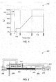
- FIG. 1 illustrates a plot 100 of an example of a voltage limit curve at the point of connection (POC) of a power generation system during a fault event.
- the power generation system is required by the grid code to ride through such a fault event without disconnecting.
- grid authorities expect generators to stay connected when a voltage dip of a certain magnitude and duration occurs at the POC.
- the grid code requirements are aimed in preventing the sudden disconnection of great number of generators, which may contribute to the voltage dip and have negative impact on system stability.
- the grid code therefore requires that all generators to stay connected to the power grid as long as the voltage at the POC is equal or higher than the voltage limit curve shown.
- the voltage limit curve shape may vary from country to country or from one grid authority to other grid authority.
- the faults may be due to lightning and wind storms. These faults may cause a "voltage dip" of a certain magnitude and duration, depending on the type and severity of the fault and the distance of the fault from the POC.
- the plot 100 shows a horizontal axis 112 representing time in milliseconds and a vertical axis 114 representing voltage in percentage.
- the fault occurs at 0 milliseconds.
- the pre-fault voltage 116 at POC i.e., before 0 millisecond is 100% or 1 per unit.
- the voltage 118 at 0 millisecond may drop by 95% down to as low as 5% at the beginning of the fault.
- the generator is required to stay connected with the power grid even when the voltage drops to as low as 5%.
- the voltage at the POC depends on the electrical distance of the fault from POC, the type and severity of the fault, and so forth.
- the voltage drop may be less than 95 %.
- the voltage drop may be as high as 100% in the case of a zero impedance fault at the POC.
- the fault event duration is shown as 150 ms. At 150 ms, the fault is cleared or one of the zone protections is activated, thus the voltage goes up to 20%. Further at 500 ms, other zone protections are activated and the voltage returns to 90% within 1500 ms.
- a power generation system 200 having an electromagnetic braking unit 212 in accordance with aspects of the present disclosure, is depicted.
- the power generation system 200 is typically used to convert mechanical power into electrical power. For example, in a wind system, the kinetic energy of wind passing across a wind turbine is converted into mechanical power. This converted mechanical power is in turn used to generate electrical power.
- the power generation system 200 includes a prime mover 202, a rotatable shaft 204, an electrically conductive disc 206, a generator 208, and an electromagnetic braking unit 212.
- the generator 208 provides electrical power to a power grid 210.
- the prime mover 202 may be configured to create mechanical power.
- the prime mover 202 typically includes a rotor (not shown) such as the wind turbine, a gas turbine, a gas engine, or a diesel engine. Further, the prime mover 202 is mechanically coupled to the power generator 208 through the rotatable shaft 204.
- the rotatable shaft 204 includes a first end 214 and a second end 216.
- the first end 214 of the rotatable shaft 204 is coupled to the prime mover 202, while the second end 216 of the rotatable shaft 204 is coupled to a rotor of the generator 208.
- the rotatable shaft 204 may include one or more gear boxes (not shown).
- the rotatable shaft 204 is typically used to convey the mechanical power from the prime mover 202 to the power generator 208.
- the mechanical power produced at the prime mover 202 may be used to rotate the rotatable shaft 204 at a predetermined speed. This rotation of the rotatable shaft 204 in turn rotates the rotor of the generator 208 to generate electrical power.
- the generator 208 may include a three-phase generator.
- the generated electrical power at the generator 208 is transferred to the power grid 210.
- a connection point 218 of the generator 208 and the power grid 210 is referred to as the point of connection (POC).
- the generator 208 may be coupled to the power grid 210 through a power electronic converter (not shown), and in other embodiments the generator 208 may be coupled to the power grid 210 without any power electronic converter.
- the generator 208 may be coupled to the power grid 210 through a transformer (not shown) with or without power electronics.
- the power grid 210 collects the power generated from one or more generators and transmits the collected power to different locations for one or more applications.
- the electrically conductive disc 206 is rigidly coupled to the rotatable shaft 204.
- the conducing material used for the electrically conductive disc 206 may include, but is not limited to copper, aluminum and/or steel. Typically, different materials provide different torque-speed characteristics, so a further degree of freedom is available to those skilled in the art to achieve the required braking capability.
- the electrically conductive disc 206 may be a small and light disc that has almost no effect or negligible effect on the inertia of the generator 208. In one exemplary embodiment, the electrically conductive disc 206 may have a thickness of about 1.5 cm and an outer diameter of about 90 cm to provide a torque capability of about 14 kNm under rated current supply.
- the dimensions of the electrically conductive disc 206 may vary depending on the type of application, and thus, they should not be intended as limited to the exemplary ones. Since the electrically conductive disc 206 is rigidly coupled to the rotatable shaft 204, the rotational speed of the rotatable shaft 204 may be controlled by controlling the rotational speed of the electrically conductive disc 206.
- the voltage at the POC 218 may fall below a predetermined level, as depicted in FIG. 1 , due to one or more fault events in the system 200.
- a voltage fall/drop occurs in the system 200, it is likely that the electrical power injected to the grid 210 by the generator 208 is reduced.
- the mechanical power produced by the prime mover 202 is not reduced accordingly, then the mechanical power surplus is transformed into kinetic energy accelerating the rotating masses of the engine/prime mover 202 and the generator 208. Consequently, the rotor speed of the generator 208 may increase, resulting in increase of the generator rotor angle, which may lead to loss of synchronism between the generator 208 and the power grid 210. Therefore, the generator 208 will trip and fail to comply with the required grid code.
- the electromagnetic braking unit 212 is employed to help the power generation system 200 to regulate the rotational speed of the rotatable shaft 204. Further, by regulating the rotational speed of the rotatable shaft 204, the electromagnetic braking unit 212 may maintain synchronism between the generator 208 and the power grid 210. Particularly, the electromagnetic braking unit 212 receives at least one status signal from the power generation system 200.
- the status signal may be representative of a rotational speed of the rotatable shaft 204, a voltage in the power grid 210, a current at the generator 208, a mechanical power produced by the prime mover 202, a rotor angle of the generator 208, an electrical power produced by the generator 208, or combinations thereof.
- the rotor angle of the generator 208 is defined as an electrical angle between a stator voltage of the generator 208 and a voltage of the power grid 210.
- this status signal may indicate one or more fault events/conditions in the power generation system 200.
- the electromagnetic braking unit 212 may generate a control signal based on the received status signal. This generated control signal is used to apply electromagnetic braking force on the rotatable shaft 204 to regulate the rotational speed of the rotatable shaft 204, which in turn prevents loss of synchronism between the generator 208 and the power grid 210.
- the aspect of maintaining synchronism between the generator 208 and the power grid 210 will be explained in greater detail with reference to FIGs. 3 and 4 .
- the electromagnetic braking unit 212 the rotational speed of the rotatable shaft 204 is controlled and the synchronism between the generator 208 and the power grid 210 is maintained. This in turn helps the power generation system 200 to comply with the required grid code including the LVRT grid code.
- the electromagnetic braking unit 212 includes a speed sensor 302, a controller 304, and an inducting unit 306.
- the speed sensor 302 is electrically coupled to the rotatable shaft 204 to determine the rotational speed of the rotatable shaft 204.
- the speed sensor 302 sends a speed signal 308 that is representative of the rotational speed of the rotatable shaft 204 to the controller 304.
- the controller 304 may also receive at least one status signal from the components, such as the prime mover 202, the generator 208, and the power grid 210 of the power generation system 300.
- This status signal may be representative of a mechanical power produced by the prime mover 202, a current generated by the generator 208, a voltage in the power grid 210, a rotor angle of the generator 208, an electrical power produced by the generator 208, or combinations thereof.
- the controller 304 may receive the status signal that includes at least the speed signal 308, a power signal 310, 317, a current signal 312, a voltage signal 314, a rotor signal 316, or combinations thereof.
- the controller 304 receives the voltage signal 314 from the power grid 210.
- the voltage signal 314 may be representative of one or more fault events occurring in the power grid 210.
- the voltage signal 314 may indicate a fault voltage at the POC or the power grid 210, as depicted in FIG. 1 .
- one or more voltage sensors may be employed in the power grid 210 to determine the voltage signal 314.
- the controller 304 may receive the current signal 312 from the generator 208.
- the current signal 312 may be representative of the current generated by the generator 208. Also, the current signal 312 may indicate whether the current at the generator 208 is above or below a threshold current.
- one or more current sensors may be disposed on the generator 208 or at an output terminal of the generator 208 to determine the current signal 312.
- the controller 304 may receive the rotor signal 316 from the generator 208.
- the rotor signal 316 may be representative of the rotor angle of the generator 208.
- the rotor angle may be measured by integration of varying speed of the shaft 204 and predetermined synchronous speed. More specifically, the rotor angle may indicate an electrical angle between the stator voltage of the generator 208 and the voltage in the power grid 210.
- one or more sensors may be employed in the generator 208 and/or power grid 210 to determine the rotor signal 316.
- the sensors that are used to determine the current signal 312 may also be used to determine the rotor signal 316.
- the controller 304 may receive a power signal 310 from the prime mover 202 of the power generation system 300.
- the power signal 310 may be representative of the mechanical power produced by the prime mover 202.
- the power signal 310 may indicate whether the produced mechanical power is above or below a first threshold power.
- one or more power sensors may be used in the prime mover 202 to determine the power signal 310.
- the controller 304 may receive the electrical power signal 317 from the POC 218.
- the electrical power signal 317 may be representative of the electrical power produced by the generator 208.
- the power signal 310 may indicate whether the produced electrical power is above or below a second threshold power.
- the controller 304 may determine the electrical power based on the voltage and the current generated by the generator 208.
- the controller 304 may generate a control signal 318 to initiate and/or regulate the electromagnetic braking force/power on the rotatable shaft 204.
- the amount of electromagnetic braking force applied on the rotatable shaft 204 is proportional to the magnitude of the control signal 318.
- the control signal 318 may be generated based on one of these signals 308, 310, 312, 314, 316, 317 or a combination of these signals 308, 310, 312,314,316,317.
- the controller 304 may determine whether a fault event has occurred in the power grid 210 based on the received voltage signal 314. If so, the controller 304 generates the control signal 318 that is corresponding to the fault event of the power grid 210.
- the voltage signal 314 may indicate the fault event in the power grid 210.
- the controller 304 may determine whether the rotational speed of the rotatable shaft 204 is above the threshold speed based on the received speed signal 308. If so, the controller 304 generates the control signal 318 that is corresponding to the rotational speed of the rotatable shaft 204. Also, the controller 304 may generate the control signal 318 that is corresponding to the change in the rotational speed of the rotatable shaft 204. For example, if the rotational speed of the shaft 204 is 1510 rpm and the threshold speed is 1500 rpm, the control signal 318 is generated to reduce the rotational speed by 10 rpm.
- the controller 304 may determine whether the mechanical power that is produced by the prime mover 202 is above the first threshold power based on the received power signal 310. If so, the controller 304 may generate the control signal 318 that is corresponding to the mechanical power produced by the prime mover 202. Also, the controller 304 may generate the control signal 318 that is corresponding to the amount of mechanical power that is above the first threshold power. In this embodiment, the generated control signal 318 may be used to apply the braking on the electrically conductive disc 206 to reduce the rotational speed of the shaft 204.
- the controller 304 may determine whether the mechanical power that is produced by the prime mover 202 is below the first threshold power based on the received power signal 310. If so, the controller 304 may generate the control signal 318 that is corresponding to the mechanical power produced by the prime mover 202. In this embodiment, the generated control signal 318 may be used to remove the braking force that is acting on the electrically conductive disc 206. In one embodiment, the electrical power signal 317 may be used as the first threshold power for determining the control signal 318.
- the controller 304 may determine whether the electrical power that is produced by the generator 208 is below a second threshold electrical power based on the received electrical power signal 317. If so, the controller 304 may generate the control signal 318 that is corresponding to the electrical power produced by the generator 208. Also, the controller 304 may generate the control signal 318 that is corresponding to the amount of electrical power that is below the second threshold electrical power. In this embodiment, the generated control signal 318 may be used to apply the braking on the electrically conductive disc 206 to reduce the rotational speed of the shaft 204. In one embodiment, the power signal 310 received from the prime mover 202 may be used as the second threshold electrical power for determining the control signal 318.
- the controller 304 may determine whether the current at the generator 208 is above the threshold current based on the received current signal 312. If so, the controller 304 may generate the control signal 318 that is corresponding to the current at the generator 208. Also, the controller 304 may generate the control signal 318 that is corresponding to the amount of current above the threshold current.
- the controller 304 may determine whether the rotor angle of the generator 208 is above a threshold rotor angle based on the received rotor signal 316. If so, the controller 302 may generate the control signal 318 that is corresponding to the rotor angle of the generator 208.
- the controller 304 may generate the control signal 318 based on some combination of the signals 308, 310, 312, 314, 316, 317 received from the power generation system 300.
- the controller 304 may generate the control signal 318 only if each of the following conditions is present: the voltage in the power grid 210 is below a threshold voltage, the generator current is above a threshold current, and the rotational speed of the shaft 204 is above a threshold speed. Otherwise, the controller 318 may ignore these received signals 308, 310, 312, 314, 316, and no control signal 318 is generated.
- the controller 304 may generate the control signal 318 if the voltage at the power grid is 50% below a normal voltage and the generator current is 10% above a normal current. It is to be noted that the normal voltage and the normal current are referred to their respective voltage and current in the system 300 during normal conditions when no fault events/conditions occurred in the system 300.
- the controller may additionally generate a control signal 320 based on one or more of the signals 308, 310, 312, 314, 316, 317 received from the power generation system 300.
- the control signal 320 is provided to the prime mover 202 to control or regulate the generation of mechanical power for a determined time period.
- the controller 304 may send the control signal 320 to stop or regulate the generation of mechanical power at the prime mover 202 for the determined time period.
- the controller 304 may send another control signal to the prime mover 202 to resume generating the mechanical power and to quickly recover the full mechanical power.
- the size and braking capability of the braking system 212 and related power electronics and power source may be substantially reduced.
- the controller 304 may be configured to drive the inducting unit 306 to initiate and/or regulate the electromagnetic braking force on the electrically conductive disc 206.
- the electromagnetic braking force is regulated or varied depending upon the magnitude of control signal 318 provided by the controller 304.
- the controller 304 may drive the inducting unit 306 to remove the electromagnetic braking force that is applied on the electrically conductive disc 206.
- the control signal 318 may be provided to the inducting units 306 to stop or remove the electromagnetic braking force that is acting on the electrically conductive disc 206.
- the controller 304 is determining in advance that the rotational speed of the shaft 204 may go down due to the drop in the mechanical power of the prime mover 202.
- the power generation system 300 may have additional time to maintain synchronism between the generator 208 and the grid 210.
- the inducting unit 306 is communicatively coupled to the controller 304 to receive the control signal 318 and apply the electromagnetic force based on the control signal 318. Particularly, the inducting unit 306 creates a first magnetic field across the electrically conductive disc 206. In one embodiment, this first magnetic field is corresponding to the magnitude of the received control signal 318.
- the electrically conductive disc 206 that is coupled to the rotatable shaft 204 rotates through this created first magnetic field. More specifically, the amplitude and/or direction of the first magnetic field may be varied while the electrically conductive disc 206 is rotating along the rotatable shaft 204. As a result of these variations in the first magnetic field that is linked to each portion of the electrically conductive disc 206, eddy currents are induced in the electrically conductive disc 206. These induced eddy currents may further create a second magnetic field that is opposing the first magnetic field to resist rotation of the electrically conductive disc 206.
- the rotational speed of the rotatable shaft 204 is controlled below the threshold speed to maintain synchronism between the power generator 208 and the power grid 210.
- the rotation of the electrically conductive disc 206 is resisted by the electromagnetic braking system 212 to maintain synchronism between the power generator 208 and the power grid 210.
- the accelerating power at the generator 208 may be dissipated as heat across the electrically conductive disc 206.
- the aspect of applying the electromagnetic force will be explained in greater detail with reference to FIG. 4 .
- the rotational speed of the rotatable shaft 204 is regulated, which in turn helps the power generator 208 to maintain synchronism with the power grid 210 and comply with the grid code requirements.
- FIG. 4 is a diagrammatical representation of another detailed electromagnetic braking unit in a power generation system 400 showing additional details of an embodiment wherein the inducting unit 306 includes a power source 402, an electrical switch 404, and inductors 406, in accordance with aspects of the present disclosure.
- the inductors 406 may include one or more electrical windings that are disposed proximate to the electrically conductive disc 206. "Proximate" as used herein means close enough to the electrically conductive disc that the described breaking function can be achieved. In one non-limiting example, the inductors are situated about 5 mm from the electrically conductive disc.
- the inductors 406 may be arranged in one or more layers facing the electrically conductive disc 206. Also, the inductors 406 may be arranged in one or more groups facing either one side of the conductive disc 206 or both the sides of the conductive disc 206. Also, these groups of inductors 406 may be connected to a single electrical circuit or to a plurality of electrical circuits.
- each of the groups of inductors 406 may be separately connected to a different electrical circuit, in parallel, to improve the response time of the braking action, and also to aim at better matching the groups of inductors 406 to the available switch 404 and the power source 402.
- the electrical switch 404 is configured to regulate the AC or DC current that is provided from the power source 402 to the inductors 406.
- the electrical switch 404 may include an "Insulated-Gate-Bipolar-Transistor" (IGBT) switch that is controllable by the control signal 318 sent to a gate terminal of the switch.
- IGBT Insulated-Gate-Bipolar-Transistor
- the switch 404 toggles between ON state and OFF state depending upon the control signal 318 received from the controller 304.
- the control signal 318 may include one or more pulses depending upon the amount of electromagnetic braking force required on the electrically conductive disc 206. If a positive pulse of the control signal 318 is provided to the gate terminal of the switch 404, the switch is turned to ON state.
- the switch 404 if a negative pulse of the control signal 318 or no control signal 318 is provided to the gate terminal of the switch 404, the switch 404 is turned to OFF state.
- the switch 404 When the switch 404 is in the ON state, the AC or DC current is provided to the inductors 406, while the switch 404 is in the OFF state, no AC or DC current is provided to the inductors 406.
- the electrical switch 404 regulates the AC or DC current received from the power source 402. For example, if the switch 404 is turned ON and OFF 100 times and the turn ON and OFF time period are same, the switch 404 provides 50% of the total current.
- the inductors 406 create a first magnetic field across the electrically conductive disc 206 based on the received AC or DC current from the power source 402.
- the strength of the magnetic field is corresponding to the regulated AC or DC current received from the switch 404.
- This created first magnetic field further induces eddy currents in the electrically conductive disc 206.
- the eddy currents are induced in the electrically conductive disc when the electrically conductive disc 206 rotates through the created first magnetic field.
- These induced eddy currents may further create a second magnetic field that is opposing the first magnetic field to resist rotation of the electrically conductive disc 206.
- the rotational speed of the rotatable shaft 204 is controlled below the threshold speed to maintain synchronism between the power generator 208 and the power grid 210.
- the accelerating power at the generator 208 may be dissipated as heat across the electrically conductive disc 206.
- the power generator 208 maintains synchronism with the power grid 210, which in turn complies with the grid code requirements.
- a flow chart 500 illustrating a method for maintaining synchronism between a power generator and a power grid in a power generation system, in accordance with aspects of the present disclosure, is depicted.
- the method begins at step 502, where at least one status signal that is representative of a rotational speed of the rotatable shaft 204, a voltage in the power grid 210, a current at the generator 208, a mechanical power produced by the prime mover 202, a rotor angle of the generator 208, an electrical power from the generator or combinations thereof, is received from the power generation system 300.
- a controller 304 is configured to receive the status signal from the components, such as the prime mover 202, the generator 208, and the power grid 210 of the power generation system 300. Particularly, the controller 304 may receive the status signal that includes at least one of a voltage signal 314 from the power grid 210, a current signal 312 from the generator 208, a speed signal 308 from the rotatable shaft 204, a power signal 310 from the prime mover 202, a rotor signal 316 from the generator 208 and/or a power signal 317 from the generator.
- the voltage signal 314 may indicate a fault voltage in the power grid 210.
- the speed signal 308 may indicate the rotational speed of the shaft 204
- the current signal 312 indicate the current generated by the generator 208
- the power signal 310 may indicate the mechanical power produced by the prime mover 202
- the rotor signal 316 may indicate the rotor angle of the generator 208
- the power signal 317 may indicate the electrical power produced by the generator 208.
- a control signal 318 is determined based on one or more of these received status signals 308, 310, 312, 314, 316, 317.
- the controller 304 determines whether the rotational speed of the rotatable shaft 204 is above a threshold speed from the received status signal. If so, the controller 304 generates the control signal 318 that is corresponding to the rotational speed of the rotatable shaft 204.
- the controller 304 may verify the status signal to detect any fault event in the power grid 210. If a fault event has occurred in the power grid 210, the controller 304 may determine the control signal 318 corresponding to the fault event.
- the controller 304 may verify the rotational speed of the rotatable shaft 204. If the rotational speed of the rotatable shaft 204 is above a threshold speed, the controller 304 may determine the control signal 318 that is proportional to the amount of rotational speed that is increased above the threshold speed. It is to be noted that the controller 304 may generate the control signal 318 based on any combination of the signals 308, 310, 312, 314, 316, 317 and is not limited to the above mentioned combination. Thereafter, the determined control signal 318 is provided to inductors 306 that are disposed proximate to an electrically conductive disc 206.
- an electromagnetic braking force is applied on the rotatable shaft 204 when commanded by the control signal 318 to regulate the rotational speed of the rotatable shaft 204, which in turn helps to maintain synchronism between the power generator 208 and the power grid 210.
- the inducting unit 306 may apply the electromagnetic braking force on the rotatable shaft 204.
- the inducting unit 306 may create a first magnetic field that is corresponding to the control signal 318 received from the controller 304. This first magnetic field further induces eddy currents in the electrically conductive disc 206 when the electrically conductive disc 206 rotates through the first magnetic field.
- the induced eddy currents in the electrically conductive disc 206 may create a second magnetic field around the electrically conductive disc 206. This created second magnetic field opposes the first magnetic field to resist the rotation of the electrically conductive disc 206.
- the electromagnetic braking force is applied on the rotatable shaft 204 via the electrically conductive disc 206 to maintain synchronism between the power generator 208 and the power grid 210.
- FIG. 6 a diagrammatical representation of inductors 406 arranged at one side of the electrically conductive disc 206, in accordance with aspects of the present disclosure is depicted.
- the inductors 406 may be arranged in one or more layers facing the electrically conductive disc 206.
- the inductors 406 may be arranged in one or more groups facing one side of the electrically conductive disc 206.
- a back iron disc (not shown) comprising magnetic steel for conducting magnetic flux may be coupled to the inductors 406 at a first side of the inductors 406 that is opposite to a second side facing the electrically conductive disc 206.
- the inductors 406 and the back iron disc may be made of same piece of material and/or used as a single unit.
- the inductors 406 are arranged in one or more groups facing both the sides of the electrically conductive disc.
- a back iron disc (not shown) may be coupled to the inductors 406 for conducting magnetic flux. Since the inductors 406 are arranged on both the sides of the electrically conductive disc, the amount of braking force applied on the electrically conductive disc may be significantly improved.
- the one or more groups of inductors 406 may be connected to a single electrical circuit 802, as depicted in FIG. 8 .
- the electrical circuit 802 may include the components, such as the electrical switch 404 and the power source 402 of FIG. 4 . As the inductors 406 are connected to one electrical circuit 802, the cost of power electronics in the electromagnetic braking system 212 may be substantially reduced.
- the inductors 406 may be connected to a plurality of electrical circuits 902, 904, 906, 908, 910, 912, 914.
- each of the groups of inductors 406 may be separately connected to a different electrical circuit, in parallel, to improve the response time of the braking action, and also to aim at better matching the groups of inductors 406 to the available switch 404 and the power source 402.
- the various embodiments of the system and the method for synchronizing the power generator with the power grid aid in riding LVRT code at a very low cost.
- the power electronics employed in the power generation system are very small in terms of power (e.g. less than 1kW power needed for 1000kW braking power) and therewith in terms of size and price.
- small and light electrically conductive disc is employed that has almost no effect on the inertia of the generator, and hence, dynamic performance of the generator is improved.
- the electromagnetic braking force is independent of the voltage conditions and grid strength.
Landscapes
- Engineering & Computer Science (AREA)
- Power Engineering (AREA)
- Life Sciences & Earth Sciences (AREA)
- Sustainable Development (AREA)
- Sustainable Energy (AREA)
- Chemical & Material Sciences (AREA)
- Combustion & Propulsion (AREA)
- Mechanical Engineering (AREA)
- General Engineering & Computer Science (AREA)
- Control Of Eletrric Generators (AREA)
- Braking Arrangements (AREA)
- Regulating Braking Force (AREA)
Applications Claiming Priority (1)
| Application Number | Priority Date | Filing Date | Title |
|---|---|---|---|
| US13/536,245 US9413217B2 (en) | 2012-06-28 | 2012-06-28 | Electromagnetic braking systems and methods |
Publications (2)
| Publication Number | Publication Date |
|---|---|
| EP2680433A2 true EP2680433A2 (de) | 2014-01-01 |
| EP2680433A3 EP2680433A3 (de) | 2018-04-11 |
Family
ID=48746281
Family Applications (1)
| Application Number | Title | Priority Date | Filing Date |
|---|---|---|---|
| EP13173645.6A Withdrawn EP2680433A3 (de) | 2012-06-28 | 2013-06-25 | Elektromagnetische Bremssysteme und Verfahren |
Country Status (4)
| Country | Link |
|---|---|
| US (1) | US9413217B2 (de) |
| EP (1) | EP2680433A3 (de) |
| CN (1) | CN103516272B (de) |
| BR (1) | BR102013016638A2 (de) |
Cited By (6)
| Publication number | Priority date | Publication date | Assignee | Title |
|---|---|---|---|---|
| EP2988412A1 (de) * | 2014-07-24 | 2016-02-24 | General Electric Company | System und verfahren zur verbesserung der ansprechzeit einer bremseinheit |
| EP3032684A1 (de) * | 2014-12-11 | 2016-06-15 | General Electric Company | Stromerzeugungssystem und verfahren mit resistivem bremsvermögen |
| WO2017027008A1 (en) * | 2015-08-10 | 2017-02-16 | General Electric Company | System and method for generator braking using laminated brake components |
| CN106968887A (zh) * | 2016-07-28 | 2017-07-21 | 湖南三人能源科技股份有限公司 | 一种风力发电系统的稳速方法及系统 |
| RU2676754C1 (ru) * | 2018-01-09 | 2019-01-11 | Федеральное Государственное Бюджетное Образовательное Учреждение Высшего Образования "Новосибирский Государственный Технический Университет" | Способ электрического торможения синхронного генератора |
| CN115539299A (zh) * | 2022-10-25 | 2022-12-30 | 哈电风能有限公司 | 一种风力发电机组偏航电机柔性抱闸控制方法及系统 |
Families Citing this family (18)
| Publication number | Priority date | Publication date | Assignee | Title |
|---|---|---|---|---|
| US9796364B2 (en) * | 2009-03-30 | 2017-10-24 | General Electric Company | Apparatus and method for advanced anti-skid brake and traction controls |
| US9601918B2 (en) | 2012-06-28 | 2017-03-21 | General Electric Company | Systems and methods for controlling acceleration of a power generator |
| US9413217B2 (en) | 2012-06-28 | 2016-08-09 | General Electric Company | Electromagnetic braking systems and methods |
| US9407187B2 (en) | 2012-06-28 | 2016-08-02 | General Electric Company | System and method for improving response time of a braking unit |
| TWI532915B (zh) * | 2013-07-24 | 2016-05-11 | 新高能源科技股份有限公司 | 具減速控制系統的垂直式風車 |
| DE102014202198B4 (de) * | 2014-02-06 | 2026-03-05 | Robert Bosch Gmbh | Verfahren zur Überprüfung eines automatischen Parkbremssystems |
| US20170353035A1 (en) * | 2014-12-17 | 2017-12-07 | United Technologies Corporation | Islanding detection method based on torque oscillations of internal combustion engines |
| US9537301B1 (en) | 2015-08-07 | 2017-01-03 | General Electric Company | System and method for generator braking |
| US9920743B2 (en) * | 2015-10-21 | 2018-03-20 | General Electric Company | Wind turbine deceleration method and system |
| CN105577158A (zh) * | 2015-12-18 | 2016-05-11 | 苏州权素船舶电子有限公司 | 一种自动感应旋转开关 |
| US10205414B2 (en) * | 2016-05-24 | 2019-02-12 | General Electric Company | Systems and methods for adjusting operations of a gas turbine following a transient event |
| US10458206B2 (en) * | 2016-10-06 | 2019-10-29 | Saudi Arabian Oil Company | Choke system for wellhead assembly having a turbine generator |
| CN106788017B (zh) * | 2016-11-11 | 2019-05-17 | 中国农业大学 | 一种小型定桨距风力发电机辅助限速系统及方法 |
| FR3060239A1 (fr) * | 2016-12-14 | 2018-06-15 | Ge Energy Products France Snc | Procede de determination d'un profil de reponse en statisme d'une machine electrique reliee a un reseau electrique |
| AU2022266129B2 (en) * | 2021-04-30 | 2024-12-05 | Siemens Gamesa Renewable Energy Innovation & Technology S.L. | A wind power facility and method |
| JP7695037B2 (ja) * | 2021-05-10 | 2025-06-18 | ナブテスコ株式会社 | 風車制動制御装置および風車 |
| EP4355956B1 (de) * | 2021-06-16 | 2025-07-23 | Junttan OY | Rammhammer und verfahren zum rammen eines pfahls |
| EP4355955B1 (de) | 2021-06-16 | 2025-07-23 | Junttan OY | Rammhammer und verfahren zum rammen eines pfahls |
Family Cites Families (51)
| Publication number | Priority date | Publication date | Assignee | Title |
|---|---|---|---|---|
| GB191506407A (en) * | 1915-04-29 | 1916-03-23 | British Thomson Houston Co Ltd | Improvements in and relating to the Regulation of Dynamo Electric Machines. |
| GB444854A (en) | 1934-04-23 | 1936-03-30 | British Thomson Houston Co Ltd | Improvements in and relating to dynamo electric machines |
| JPS60167602A (ja) | 1984-02-06 | 1985-08-31 | Hitachi Ltd | 電気車のうず電流制御装置 |
| WO1988008636A1 (en) | 1987-04-30 | 1988-11-03 | Froude Consine Ltd | Eddy-currents machine for drive and braking purposes |
| US5485901A (en) | 1990-02-14 | 1996-01-23 | Fujitsu Ltd. | Electromagnetic brake |
| DE19532136A1 (de) * | 1995-08-31 | 1997-03-06 | Clouth Gummiwerke Ag | Antriebssystem, insbesondere für ein Kraftfahrzeug, und Verfahren zum Betreiben desselben |
| US5821712A (en) | 1996-05-23 | 1998-10-13 | Fittje; James E. | Electro-magnetic braking system |
| US5685398A (en) | 1996-06-28 | 1997-11-11 | Rexnord Corporation | Fast response adjustable brake |
| DE29720198U1 (de) * | 1997-11-14 | 1999-03-25 | Jenbacher Energiesysteme AG, Jenbach | Stromerzeugungsanlage |
| DE19860396A1 (de) | 1998-12-28 | 2000-06-29 | Bosch Gmbh Robert | Elektromotor mit elektromagnetischer Bremse |
| DE19951221A1 (de) | 1999-04-01 | 2000-10-05 | Mannesmann Ag | Windwerk, insbesondere Hebezeug, mit einem Gehäuse |
| JP3547347B2 (ja) | 1999-09-20 | 2004-07-28 | 株式会社日立製作所 | 車両用電動発電装置 |
| US6253885B1 (en) | 1999-11-03 | 2001-07-03 | Visteon Global Technologies, Inc. | Eddy current brake for automotive vehicles |
| US7273135B2 (en) | 2001-02-15 | 2007-09-25 | Integral Technologies, Inc. | Low cost magnetic brakes and motion control devices manufactured from conductive loaded resin-based materials |
| JP2002340059A (ja) | 2001-05-18 | 2002-11-27 | Oriental Motor Co Ltd | モータ用励磁作動型電磁ブレーキ |
| US6702404B2 (en) * | 2001-12-20 | 2004-03-09 | Visteon Global Technologies, Inc. | Hybrid electromagnetic/friction actuation system |
| US6619760B1 (en) | 2002-03-07 | 2003-09-16 | Visteon Global Technologies, Inc. | Closed-loop control algorithm for an eddy current braking system |
| US6871919B2 (en) | 2002-08-20 | 2005-03-29 | Visteon Global Technologies, Inc. | Method and apparatus for power management of a braking system |
| US8057358B2 (en) | 2004-01-20 | 2011-11-15 | Eaton Corporation | Control for an electromagnetic brake for a multiple-ratio power transmission that has a brake actuation counter |
| JP3987833B2 (ja) | 2004-02-27 | 2007-10-10 | 株式会社日立製作所 | 車両駆動装置 |
| US7173399B2 (en) | 2005-04-19 | 2007-02-06 | General Electric Company | Integrated torsional mode damping system and method |
| DE102005055751C5 (de) | 2005-04-21 | 2025-04-24 | Ipgate Ag | Druckmodulatorsteuerung |
| US7976434B2 (en) | 2005-12-22 | 2011-07-12 | Scott B. Radow | Exercise device |
| US7541687B2 (en) | 2006-03-10 | 2009-06-02 | Deere & Company | Method and system for managing an electrical output of a turbogenerator |
| JP4232789B2 (ja) * | 2006-04-24 | 2009-03-04 | トヨタ自動車株式会社 | 内燃機関の停止制御装置および停止制御方法 |
| US8560201B2 (en) | 2007-05-31 | 2013-10-15 | Caterpillar Inc. | Gen-Set control system having proactive load relief |
| RU2339144C1 (ru) * | 2007-07-19 | 2008-11-20 | Юрий Владимирович Шаров | Способ улучшения динамической устойчивости и демпфирования колебаний электроэнергетических систем и устройство для его осуществления |
| US7944067B2 (en) | 2008-04-01 | 2011-05-17 | General Electric Company | System and method for reducing rotor loads in a wind turbine upon detection of blade-pitch failure and loss of counter-torque |
| EP2192677A1 (de) | 2008-12-01 | 2010-06-02 | Dialog Imaging Systems GmbH | Eine Motorspule verwendender Gleichstromumformer |
| CN102301585A (zh) | 2009-01-30 | 2011-12-28 | 德风公司 | 具有lvrt能力的风力涡轮机 |
| DK2474092T3 (da) * | 2009-09-03 | 2020-07-27 | Dpm Tech Inc | Variabelt spolekonfigurationssystem, apparat og fremgangsmåde |
| JP5334785B2 (ja) | 2009-09-30 | 2013-11-06 | 三菱電機Fa産業機器株式会社 | 無励磁作動型電磁ブレーキ制御装置及び方法 |
| US8299735B2 (en) | 2010-01-27 | 2012-10-30 | Sunonwealth Electric Machine Industry Co., Ltd. | Fan system and brake control circuit thereof |
| JP2011190918A (ja) | 2010-03-17 | 2011-09-29 | Yaskawa Electric Corp | ブレーキ装置及び回転電機 |
| US8021112B2 (en) | 2010-06-29 | 2011-09-20 | General Electric Company | Methods and systems for monitoring operation of a wind turbine |
| US8471534B2 (en) * | 2010-08-26 | 2013-06-25 | General Electric Company | Fault ride through switch for power generation system |
| JP5604245B2 (ja) * | 2010-09-28 | 2014-10-08 | 株式会社日立製作所 | 鉄道車両の発電システム |
| US8428840B2 (en) | 2010-10-29 | 2013-04-23 | GM Global Technology Operations LLC | Method for controlling torque at one or more wheels of a vehicle |
| US20120201657A1 (en) | 2011-02-08 | 2012-08-09 | Icr Turbine Engine Corporation | Gas turbine engine braking method |
| US8862355B2 (en) | 2011-06-22 | 2014-10-14 | Ford Global Technologies, Llc | Method and system for engine control |
| CN102299608B (zh) | 2011-07-12 | 2013-10-16 | 北京工业大学 | 一种无电刷构造的液冷自励式电涡流缓速器 |
| US8994201B2 (en) * | 2012-04-11 | 2015-03-31 | Wind Labs, Inc. | Vertical axis wind turbine |
| US8646550B2 (en) | 2012-05-21 | 2014-02-11 | Krassimire Mihaylov Penev | Self rechargeable synergy drive for a motor vehicle |
| CN102709944B (zh) | 2012-05-24 | 2014-12-31 | 浙江运达风电股份有限公司 | 基于dgnr变桨系统的风力发电机组低电压穿越控制方法 |
| US9413217B2 (en) | 2012-06-28 | 2016-08-09 | General Electric Company | Electromagnetic braking systems and methods |
| US9601918B2 (en) | 2012-06-28 | 2017-03-21 | General Electric Company | Systems and methods for controlling acceleration of a power generator |
| TWI568149B (zh) | 2012-07-12 | 2017-01-21 | 台達電子工業股份有限公司 | 電能轉換裝置及其控制方法 |
| CN104471769B (zh) | 2012-07-20 | 2016-11-23 | 丰田自动车株式会社 | 燃料电池系统 |
| CN202685972U (zh) | 2012-08-08 | 2013-01-23 | 阳城国际发电有限责任公司 | 具有涡流缓速器的卸料车制动系统 |
| CN103089857B (zh) | 2012-12-17 | 2015-06-10 | 江苏大学 | 一种转筒式电涡流缓速器与鼓式制动器集成的制动器 |
| JP6485922B2 (ja) | 2014-01-09 | 2019-03-20 | ベックマン コールター, インコーポレイテッド | 回生ブレーキシステム |
-
2012
- 2012-06-28 US US13/536,245 patent/US9413217B2/en not_active Expired - Fee Related
-
2013
- 2013-06-25 EP EP13173645.6A patent/EP2680433A3/de not_active Withdrawn
- 2013-06-27 BR BR102013016638-3A patent/BR102013016638A2/pt not_active Application Discontinuation
- 2013-06-28 CN CN201310263947.7A patent/CN103516272B/zh not_active Expired - Fee Related
Non-Patent Citations (1)
| Title |
|---|
| None |
Cited By (6)
| Publication number | Priority date | Publication date | Assignee | Title |
|---|---|---|---|---|
| EP2988412A1 (de) * | 2014-07-24 | 2016-02-24 | General Electric Company | System und verfahren zur verbesserung der ansprechzeit einer bremseinheit |
| EP3032684A1 (de) * | 2014-12-11 | 2016-06-15 | General Electric Company | Stromerzeugungssystem und verfahren mit resistivem bremsvermögen |
| WO2017027008A1 (en) * | 2015-08-10 | 2017-02-16 | General Electric Company | System and method for generator braking using laminated brake components |
| CN106968887A (zh) * | 2016-07-28 | 2017-07-21 | 湖南三人能源科技股份有限公司 | 一种风力发电系统的稳速方法及系统 |
| RU2676754C1 (ru) * | 2018-01-09 | 2019-01-11 | Федеральное Государственное Бюджетное Образовательное Учреждение Высшего Образования "Новосибирский Государственный Технический Университет" | Способ электрического торможения синхронного генератора |
| CN115539299A (zh) * | 2022-10-25 | 2022-12-30 | 哈电风能有限公司 | 一种风力发电机组偏航电机柔性抱闸控制方法及系统 |
Also Published As
| Publication number | Publication date |
|---|---|
| BR102013016638A2 (pt) | 2017-12-19 |
| US9413217B2 (en) | 2016-08-09 |
| US20140001756A1 (en) | 2014-01-02 |
| CN103516272B (zh) | 2017-06-13 |
| EP2680433A3 (de) | 2018-04-11 |
| CN103516272A (zh) | 2014-01-15 |
Similar Documents
| Publication | Publication Date | Title |
|---|---|---|
| US9413217B2 (en) | Electromagnetic braking systems and methods | |
| EP3032684B1 (de) | Stromerzeugungssystem und verfahren mit resistivem bremsvermögen | |
| Das | Effects of momentary voltage dips on the operation of induction and synchronous motors | |
| EP1863162B1 (de) | Elektrische redundanzbremse und schutzsystem für elektrische generatoren | |
| US9601918B2 (en) | Systems and methods for controlling acceleration of a power generator | |
| EP2642626B1 (de) | Vorrichtung und Verfahren zum Betreiben einer Windturbine unter Niedrigspannungsbedingungen des Versorgungsnetzes | |
| EP2465193B1 (de) | Schutzanordnung für ein stromversorgungssystem | |
| EP2869426A1 (de) | Stromerzeugungssystem und Verfahren mit Fehlerüberbrückungsfähigkeit | |
| EP1340910A1 (de) | Permanentmagnetwindturbine und deren Regulation | |
| CA2802766A1 (en) | Generator torque control methods | |
| EP2876808A2 (de) | Stromerzeugungssystem und Verfahren mit Fehlerüberbrückungsfähigkeit | |
| EP3164935A1 (de) | Selbstauslöserschaltung zum überspannungsschutz für windkraftsystem mit doppelt gespeistem induktionsgenerator (dfig) | |
| EP3308438B1 (de) | Fehlerstrom für energieressourcen mit elektronischer leistungsschnittstelle | |
| EP2345150A1 (de) | Stromerzeugungseinheit und verfahren zum erzeugen von elektrischer energie | |
| EP3840212B1 (de) | Selektive überspannungsschutzreaktion für einen spannungsrichter zur verminderung des vorrichtungsfehlers | |
| US20180241297A1 (en) | System and method for generator braking using laminated brake components | |
| Essl et al. | LVRT-retardation-device for decentralized power plants | |
| Banham-Hall et al. | Investigating the limits to inertial emulation with large-scale wind turbines with direct-drive permanent magnet generators | |
| Foxcroft et al. | Leveraging digital relays for protection of pumped storage hydro | |
| Yan et al. | Fault tolerance of DFIG wind turbine with a series grid side passive impedance network | |
| EP2469072B1 (de) | Hydroelektrisches Turbinenbremssystem und Bremsverfahren der Turbine | |
| Kim et al. | Status of the MG installation and the result of the dummy load commissioning | |
| Teixeira | Fault ride-through capabilities: the problem, solutions and costs |
Legal Events
| Date | Code | Title | Description |
|---|---|---|---|
| PUAI | Public reference made under article 153(3) epc to a published international application that has entered the european phase |
Free format text: ORIGINAL CODE: 0009012 |
|
| AK | Designated contracting states |
Kind code of ref document: A2 Designated state(s): AL AT BE BG CH CY CZ DE DK EE ES FI FR GB GR HR HU IE IS IT LI LT LU LV MC MK MT NL NO PL PT RO RS SE SI SK SM TR |
|
| AX | Request for extension of the european patent |
Extension state: BA ME |
|
| PUAL | Search report despatched |
Free format text: ORIGINAL CODE: 0009013 |
|
| AK | Designated contracting states |
Kind code of ref document: A3 Designated state(s): AL AT BE BG CH CY CZ DE DK EE ES FI FR GB GR HR HU IE IS IT LI LT LU LV MC MK MT NL NO PL PT RO RS SE SI SK SM TR |
|
| AX | Request for extension of the european patent |
Extension state: BA ME |
|
| RIC1 | Information provided on ipc code assigned before grant |
Ipc: F16D 63/00 20060101ALI20180308BHEP Ipc: F16D 121/20 20120101ALN20180308BHEP Ipc: H02K 7/18 20060101ALI20180308BHEP Ipc: H02K 7/104 20060101ALI20180308BHEP Ipc: H02P 9/02 20060101AFI20180308BHEP |
|
| STAA | Information on the status of an ep patent application or granted ep patent |
Free format text: STATUS: REQUEST FOR EXAMINATION WAS MADE |
|
| 17P | Request for examination filed |
Effective date: 20181011 |
|
| RBV | Designated contracting states (corrected) |
Designated state(s): AL AT BE BG CH CY CZ DE DK EE ES FI FR GB GR HR HU IE IS IT LI LT LU LV MC MK MT NL NO PL PT RO RS SE SI SK SM TR |
|
| RAP1 | Party data changed (applicant data changed or rights of an application transferred) |
Owner name: AI ALPINE US BIDCO INC. |
|
| STAA | Information on the status of an ep patent application or granted ep patent |
Free format text: STATUS: THE APPLICATION IS DEEMED TO BE WITHDRAWN |
|
| 18D | Application deemed to be withdrawn |
Effective date: 20210112 |